

Crimp & seal troubleshooting
Find the failure before you replace the splice.
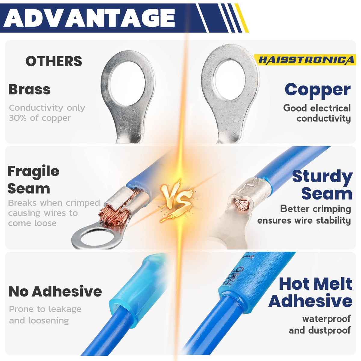
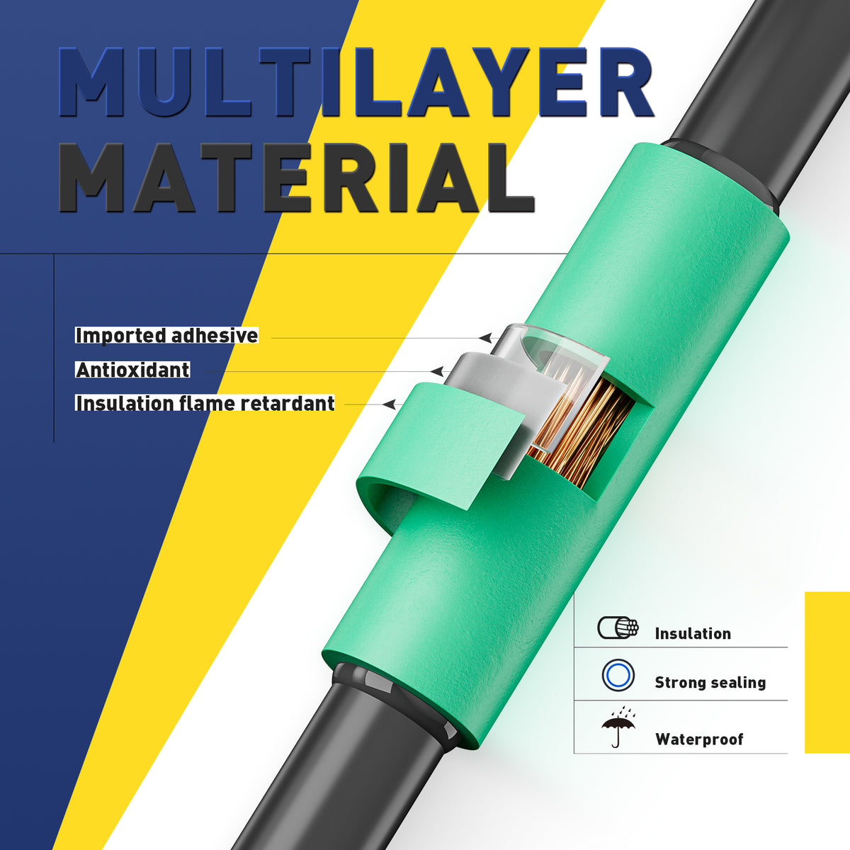
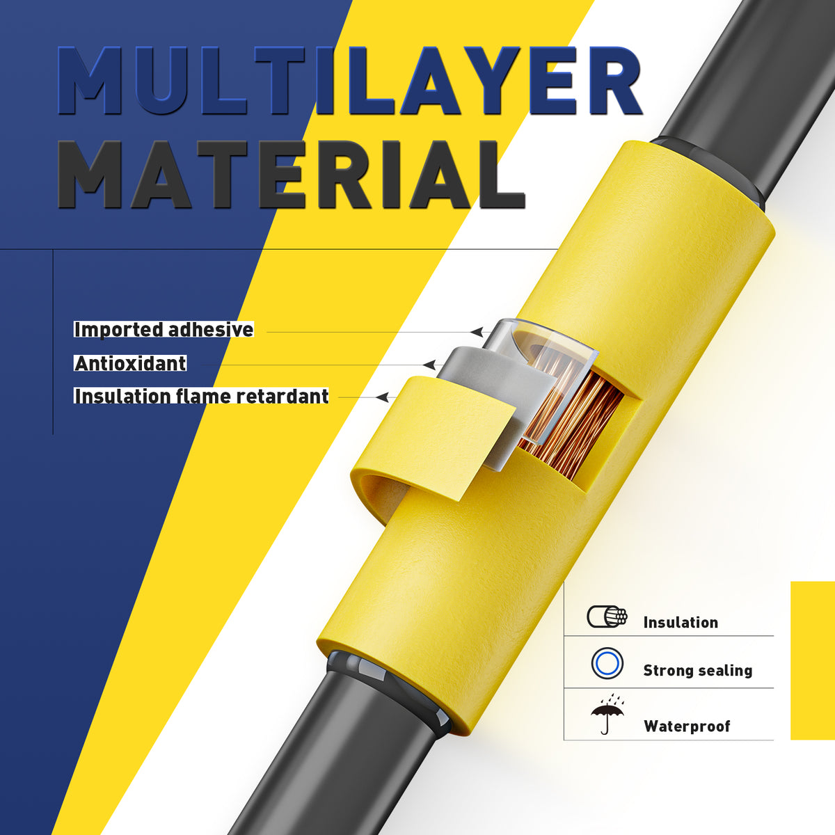
A crimp-and-seal butt connector has two separate jobs: the metal barrel grips the conductors, and the heated sleeve insulates and seals them. A tight-looking sleeve cannot prove the crimp is sound.
The wire moves or pulls out
Check wire size, insertion and die selection before blaming the connector.
Inspect the crimp →Strands are nicked or missing
Check strip length, blade alignment and stripping tension.
Correct the wire preparation →Moisture, corrosion or gaps appear
Check sleeve recovery, adhesive contact and the exposure rating.
Rebuild the seal →The connector does not fit
Match the marked wire range and insulation fit on both ends.
Choose the right size →Disconnect power before touching the splice. These symptoms guide inspection; they do not prove a single cause. A hot, burnt or repeatedly failing connection needs the circuit load, protection and cable condition checked as well.
Start with the connector type
Crimp first. Heat to seal—not to join.
This guide covers mechanical heat-shrink butt connectors. A solder-seal sleeve with a preloaded solder ring is a different product and does not use the same installation method.
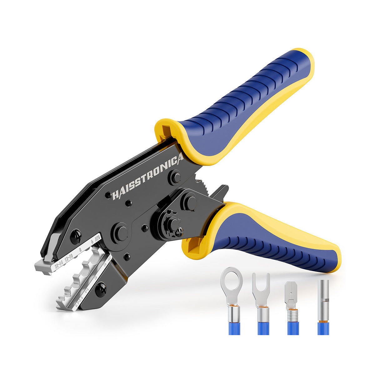
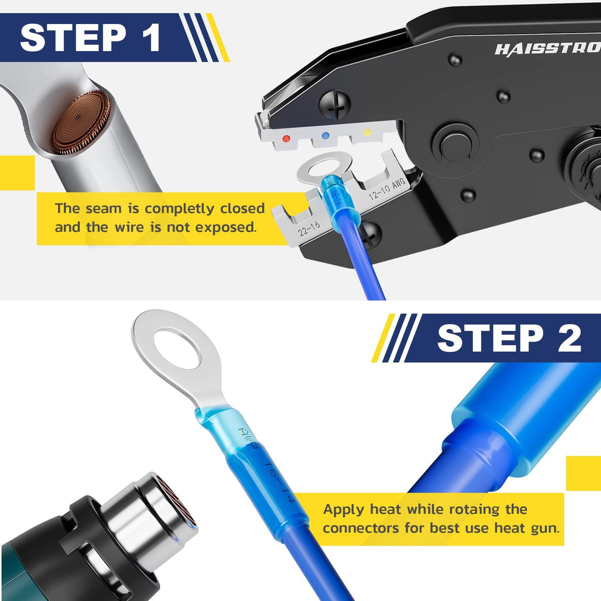
The matched die forms the electrical joint. The connector, conductor and tool must be compatible.
Controlled heating recovers the sleeve and activates its adhesive. It cannot repair missing strands, a loose barrel or an undersized wire.
Leave suitable slack and support the harness so vibration or movement is not concentrated at the splice edge.
Fix path 01 · loose wire / weak retention
Correct the crimp setup before making another joint.
A wire that slips can indicate the wrong connector size, incomplete insertion, a mismatched die or an incomplete crimp. A fully closed ratchet alone does not prove the setup was correct.
Under-crimp and over-crimp need different checks
Too little compression: check for a barrel too large for the conductor, the wrong cavity or a cycle stopped early.
Excessive or misplaced compression: check for a smaller or incompatible cavity, damaged jaws, split metal, a pierced sleeve or cut strands. Appearance is only a screening clue—not a crimp-height measurement.
- Confirm the connector family, marked AWG and specified die profile.
- Check that every strand entered the conductor barrel and insulation did not enter the crimp zone.
- Set up and verify a fresh sample before repeating the repair. Adjust the tool only as its instructions allow.
Replace a failed splice. Do not add solder or keep crushing a damaged barrel to compensate for a poor crimp.
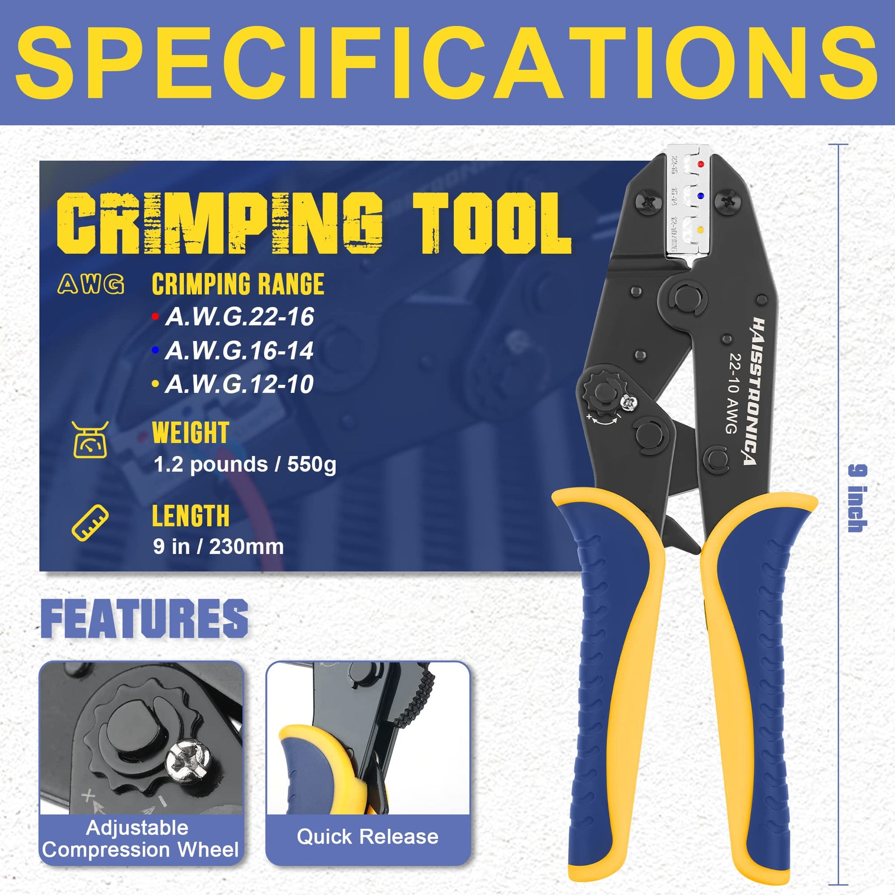
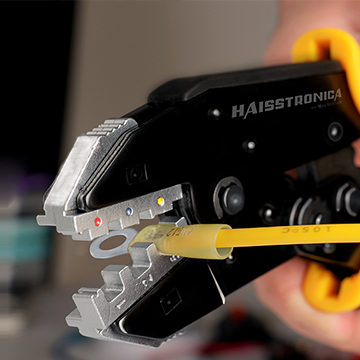
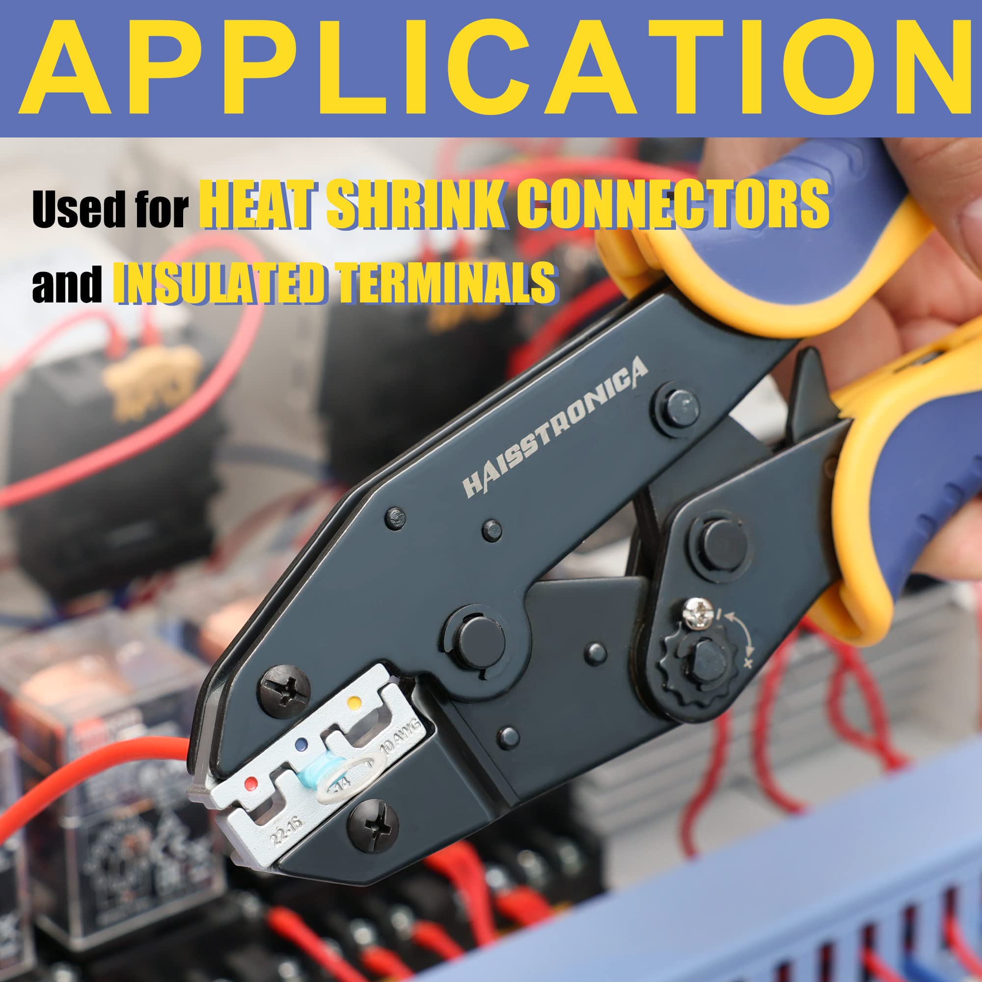
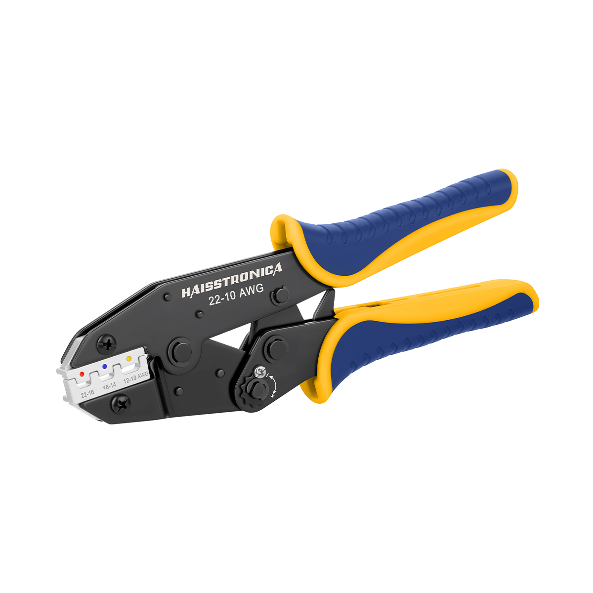
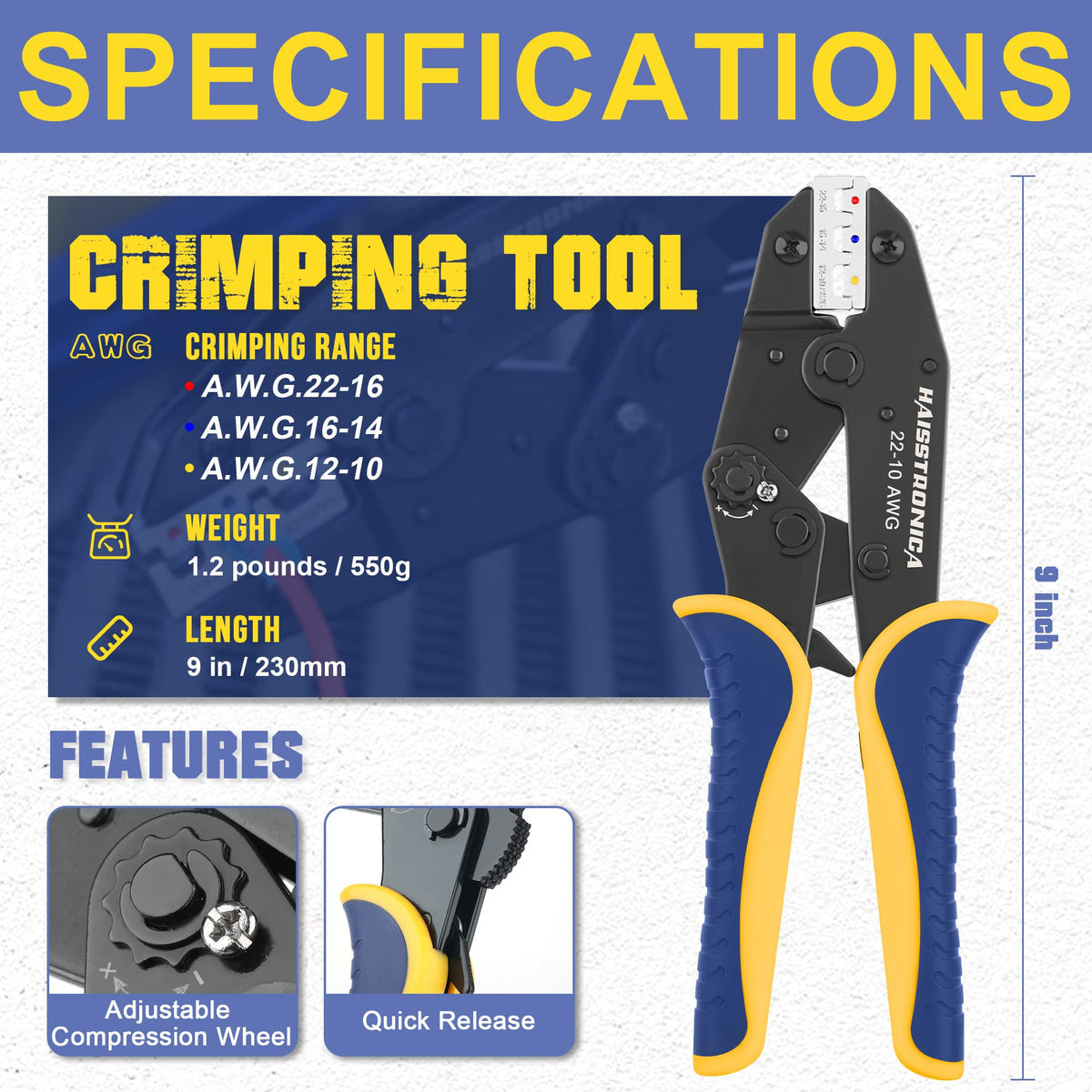
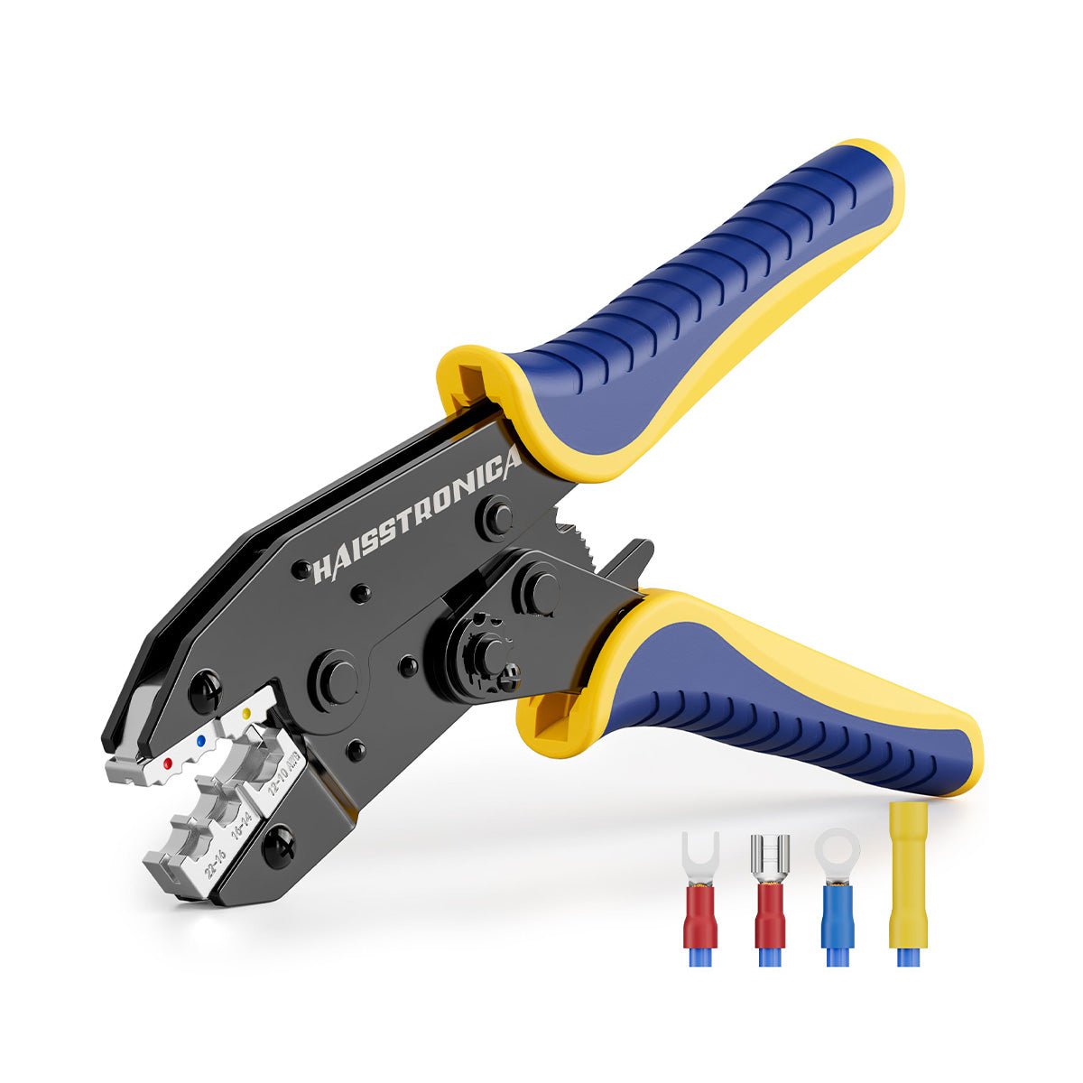
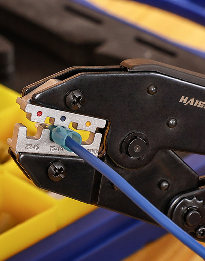
For compatible heat-shrink terminals in AWG 22–10. Smaller wire requires a correctly rated tool and die.
Fix path 02 · damaged copper / wrong strip length
Keep the full conductor intact.
Stripping too short can leave insulation in the barrel or too little conductor engagement. Stripping too long can leave bare copper beyond the intended insulation coverage.
Set the length, then test the stripping tension
- Use the connector's specified strip length; do not copy a universal length from a different terminal.
- Test on scrap from the same wire. Adjust tension for that insulation, not just the AWG.
- Inspect the full circumference for nicks, missing strands and stretched copper.
- If damaged, cut back to sound conductor and strip again. Do not trim strands to force a wire into a smaller barrel.
No sound wire left? If corrosion extends under the jacket or repeated cuts leave insufficient slack, replace the affected wire section using the permitted repair method.
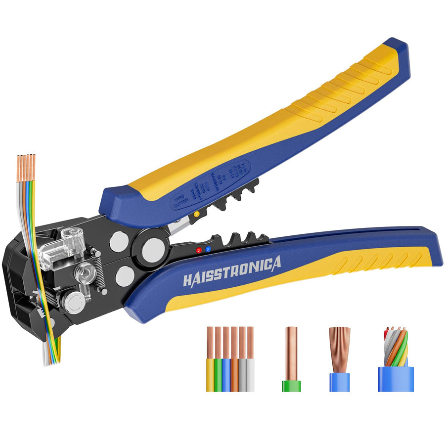
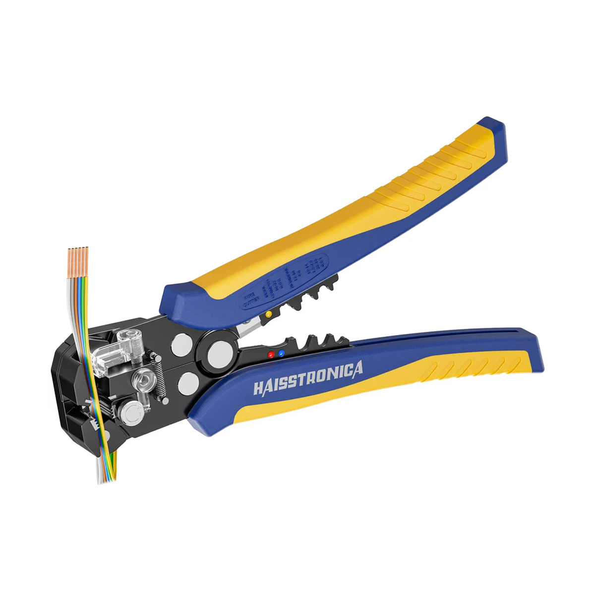
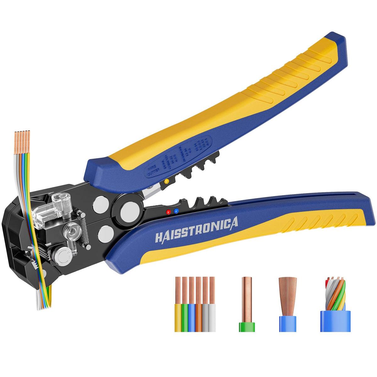
Listed stripping range: AWG 24–10. Test the setting on the actual wire; do not assume it covers AWG 26.
Fix path 03 · water entry / incomplete sealing
Replace the damaged splice, then control the heat.
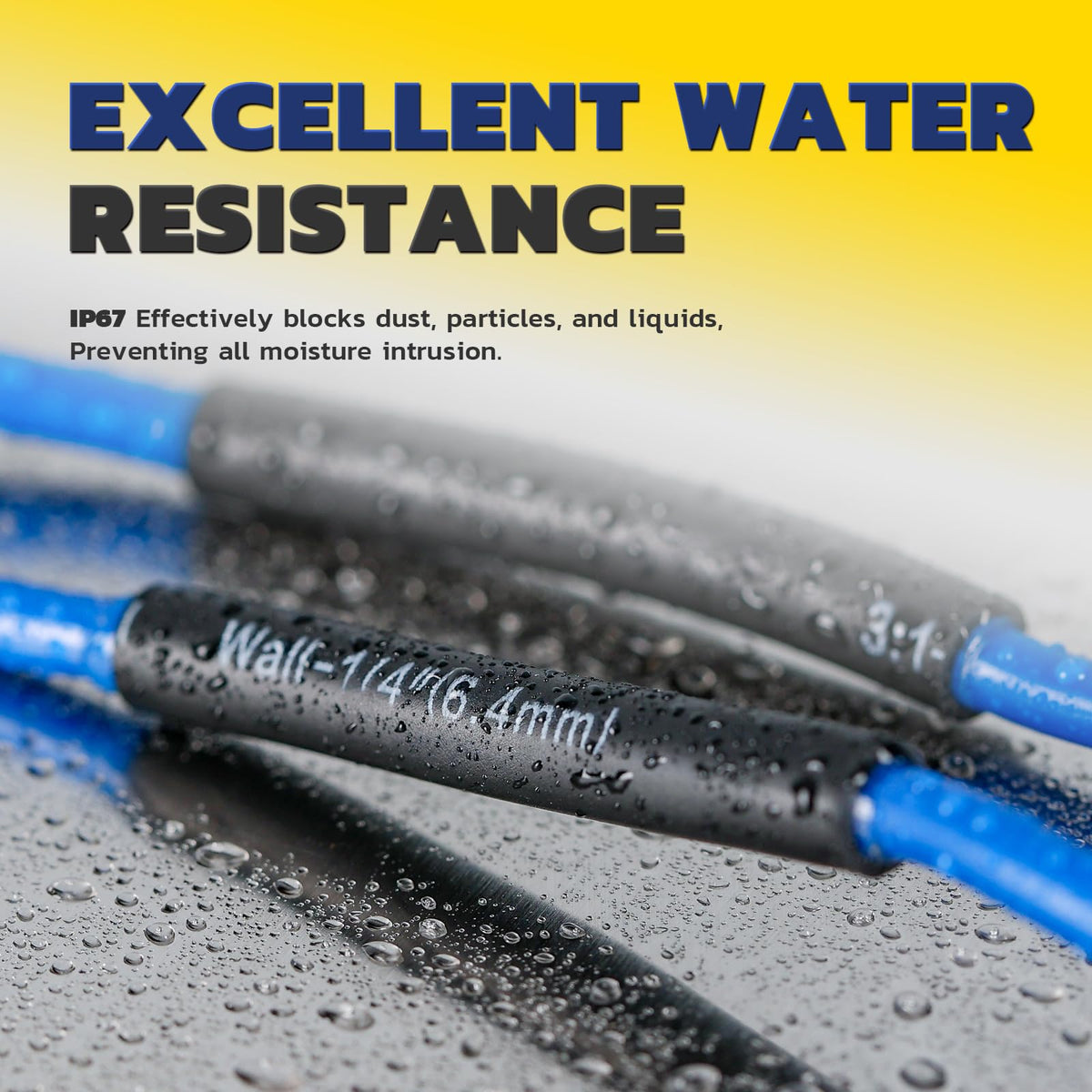
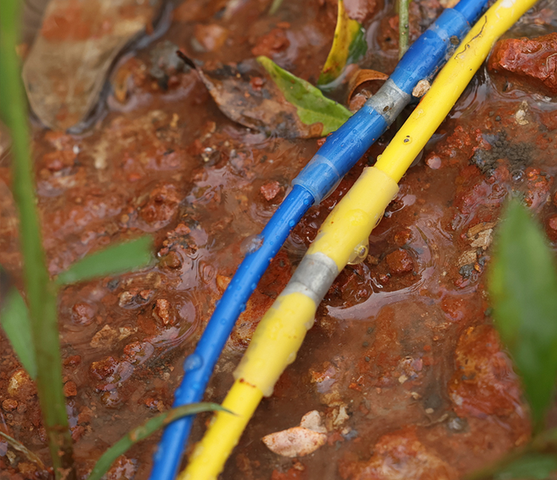
Moisture may enter through an unrecovered sleeve, poor adhesive contact, damaged insulation or an application outside the connector's rating. Heating a corroded joint again does not restore the conductor.
Start with a correctly sized, new heat-shrink connector
Cut out the failed connector and inspect the wire beyond the visible damage. Use clean, dry, sound conductors and intact insulation where the adhesive will seal.
- Confirm the sleeve can recover onto both wire jackets.
- Check the temperature, fluids and moisture exposure allowed for that exact product.
- Do not treat a general waterproof claim as approval for permanent submersion or direct burial.
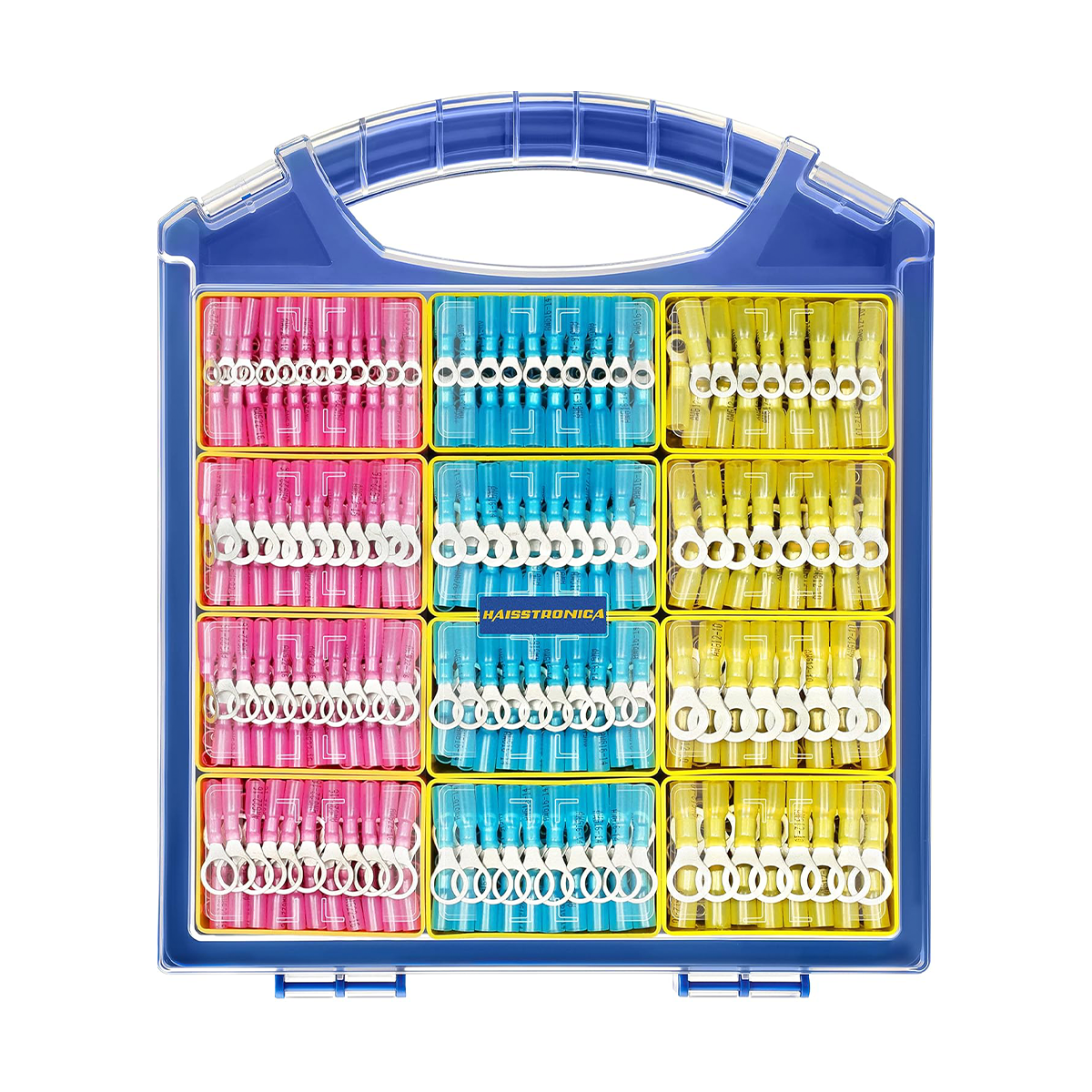
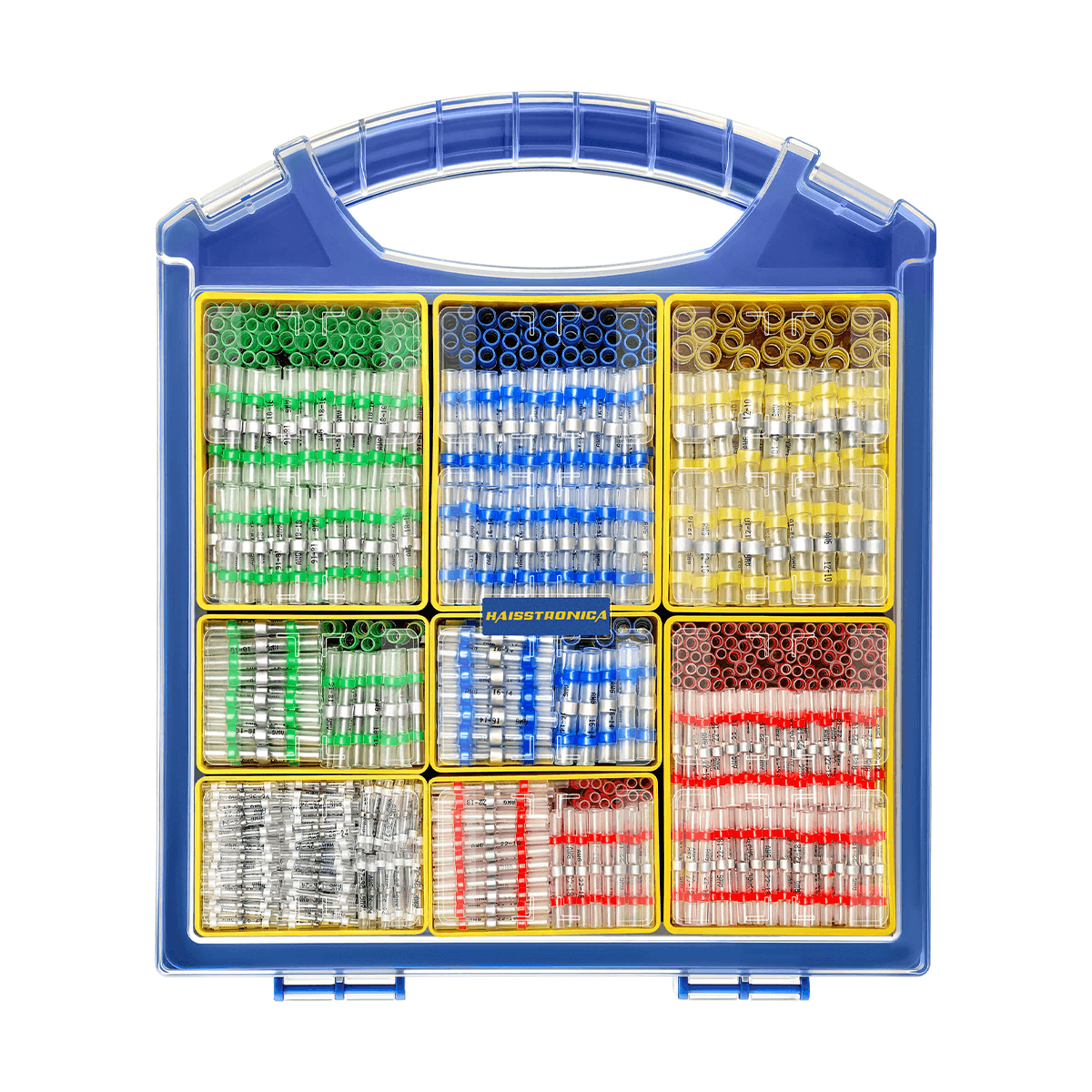
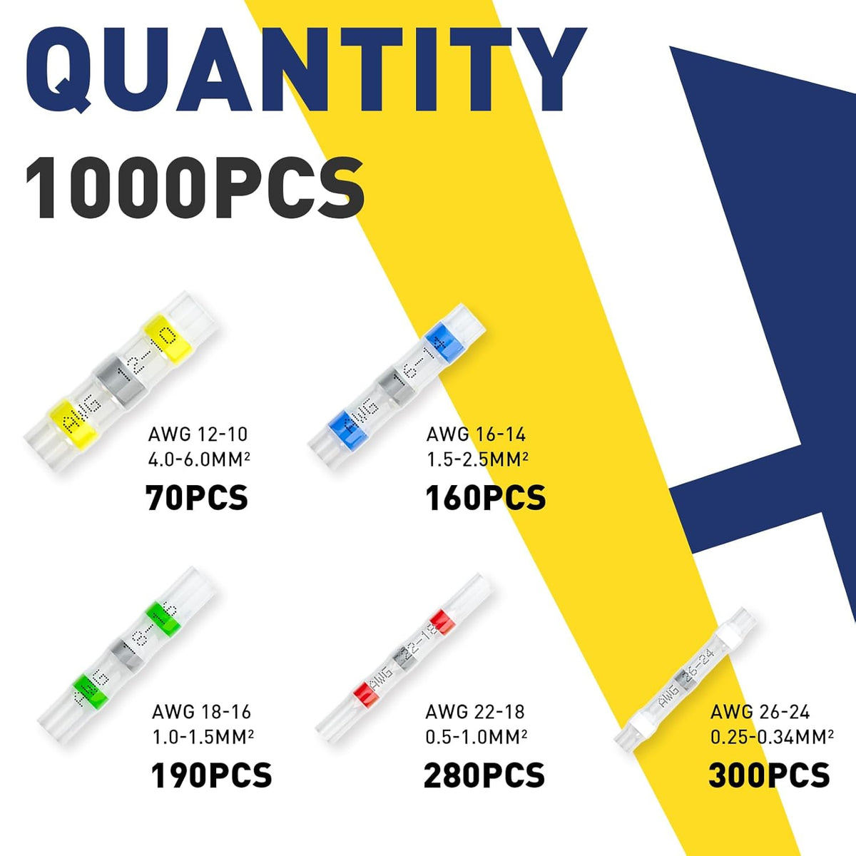
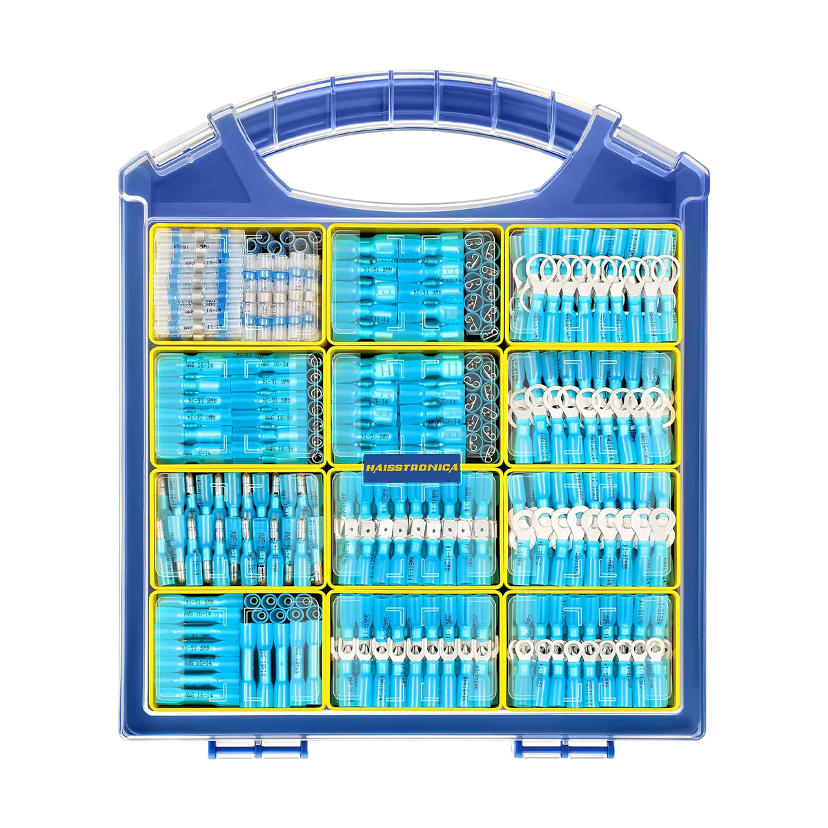
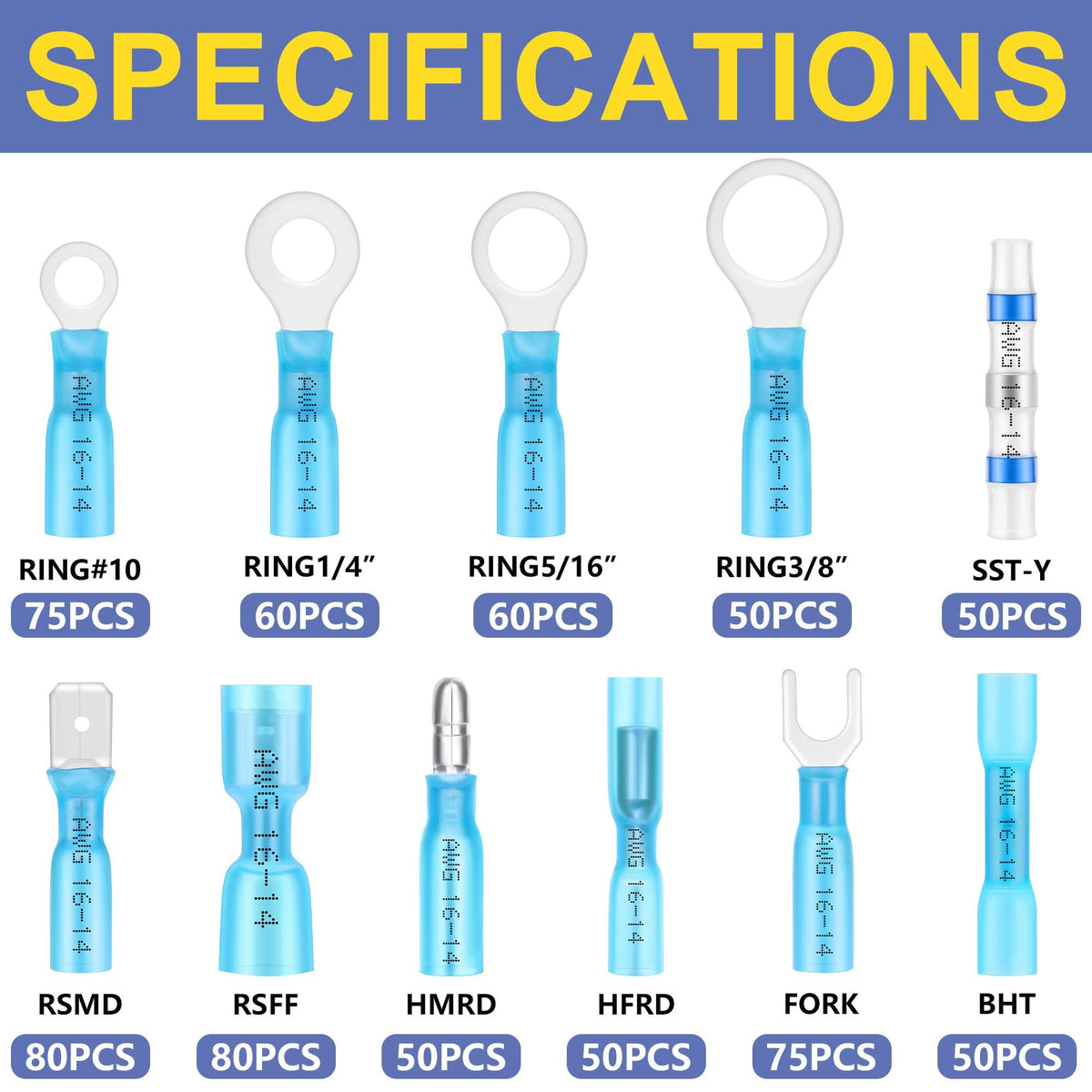
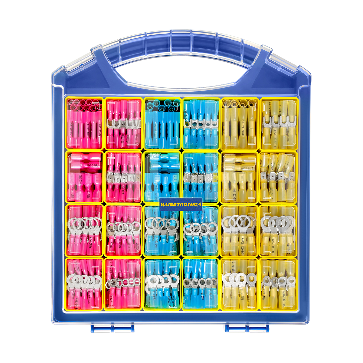
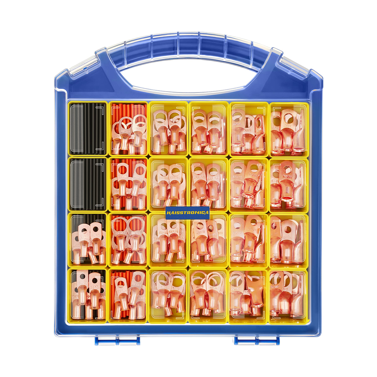
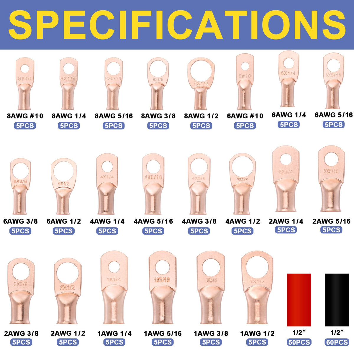
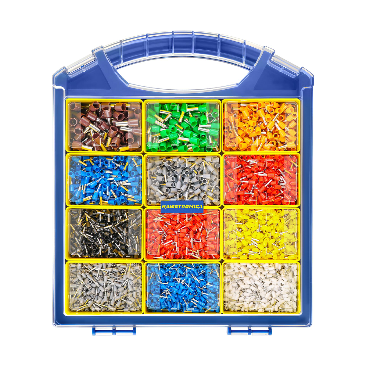
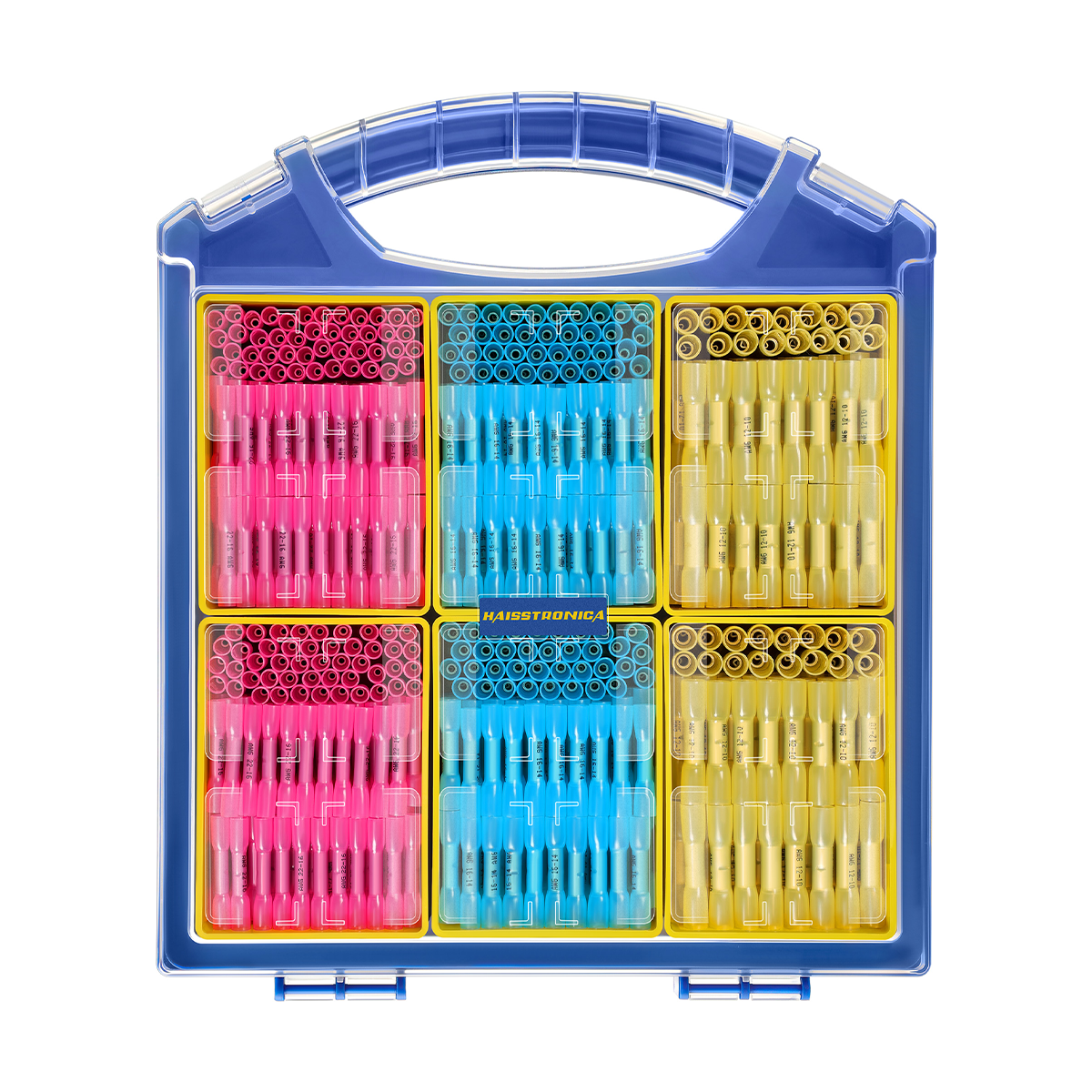
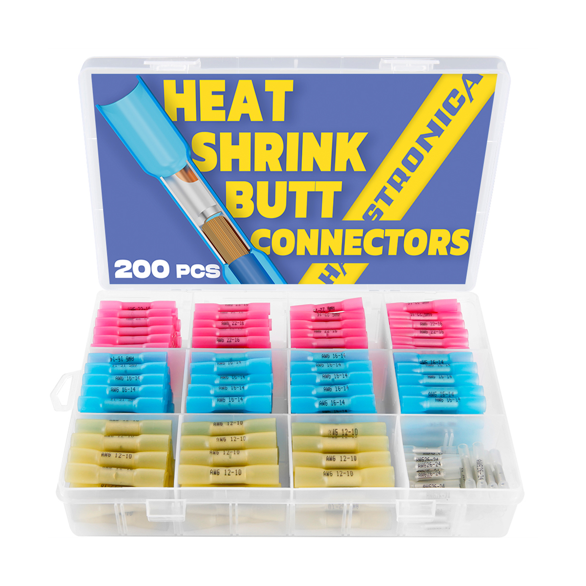
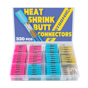
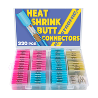
The assortment includes several size groups. Check the individual connector marking and selected kit contents before crimping.
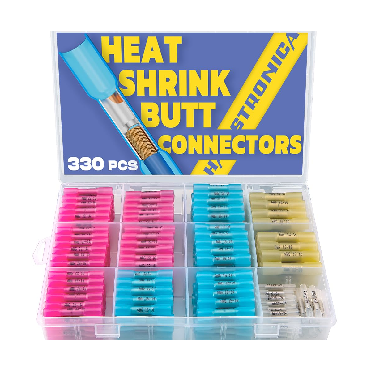
330 / 420 / 580-piece options. The assortment includes AWG 26–24 connectors, which need a smaller-wire crimp tool.
Use controlled hot air and inspect both exits
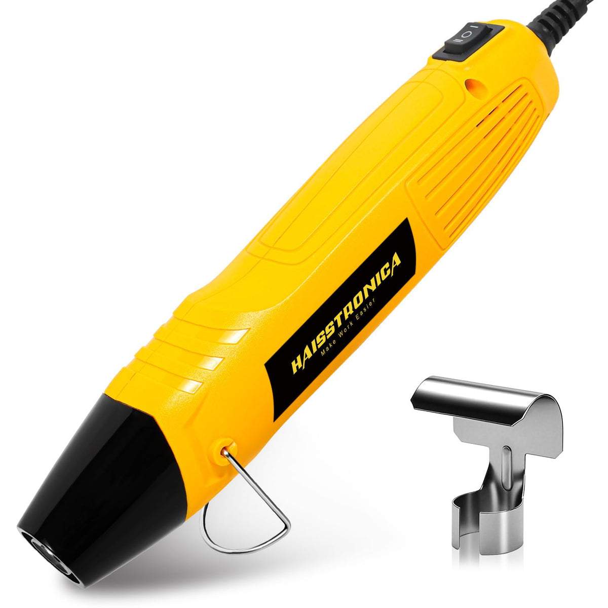
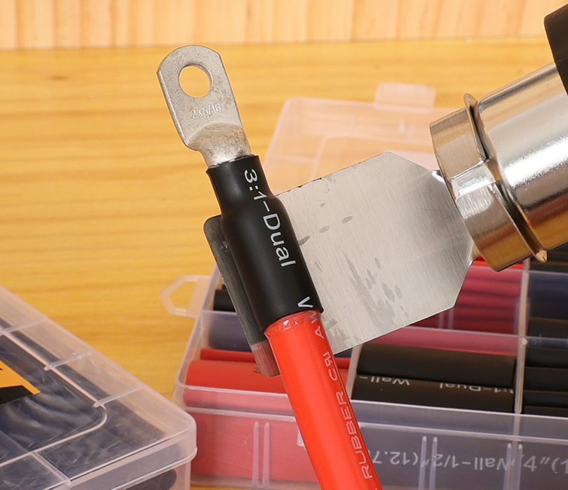
After the mechanical crimp passes inspection, heat according to the connector instructions. For this listed system, work from the center toward the ends, keeping the nozzle moving and heating evenly around the sleeve.
- Look for full sleeve recovery and the adhesive indication specified for the connector.
- Check both ends for gaps; inspect for splits, bubbles, charring or exposed copper.
- Let the splice cool without movement before final checks and cable support.
More heat is not always better. Stop if the sleeve or jacket is damaged. Do not use an open flame or heat near fuel vapors or other flammable material.
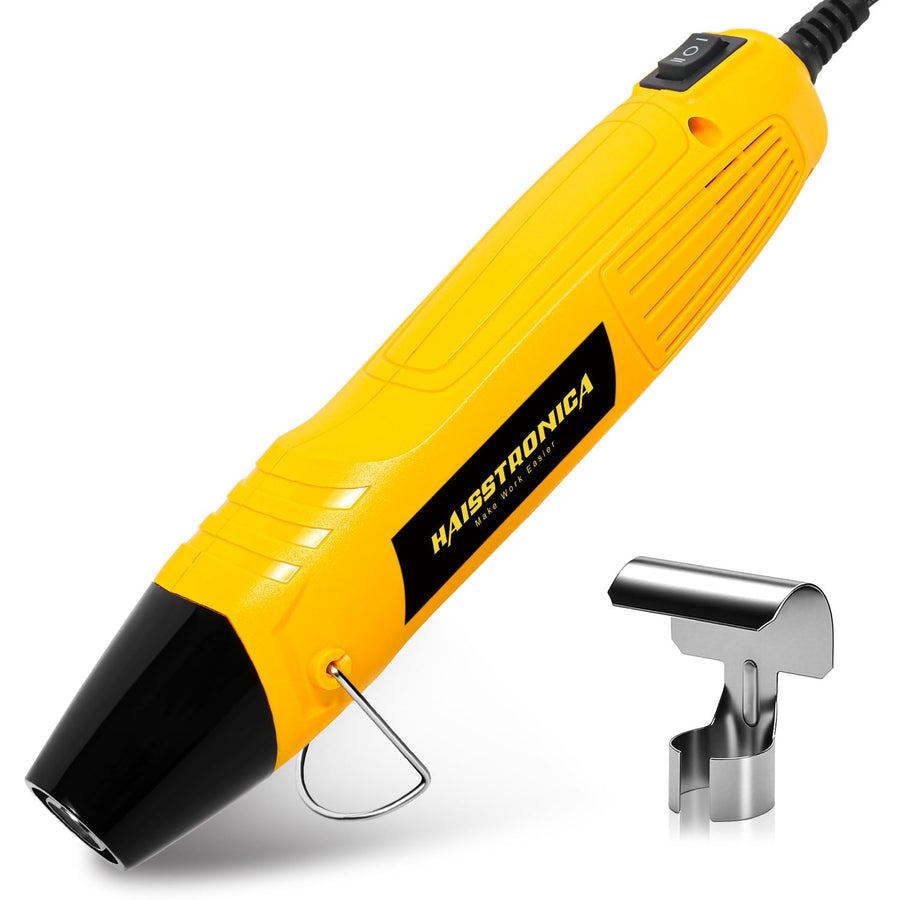
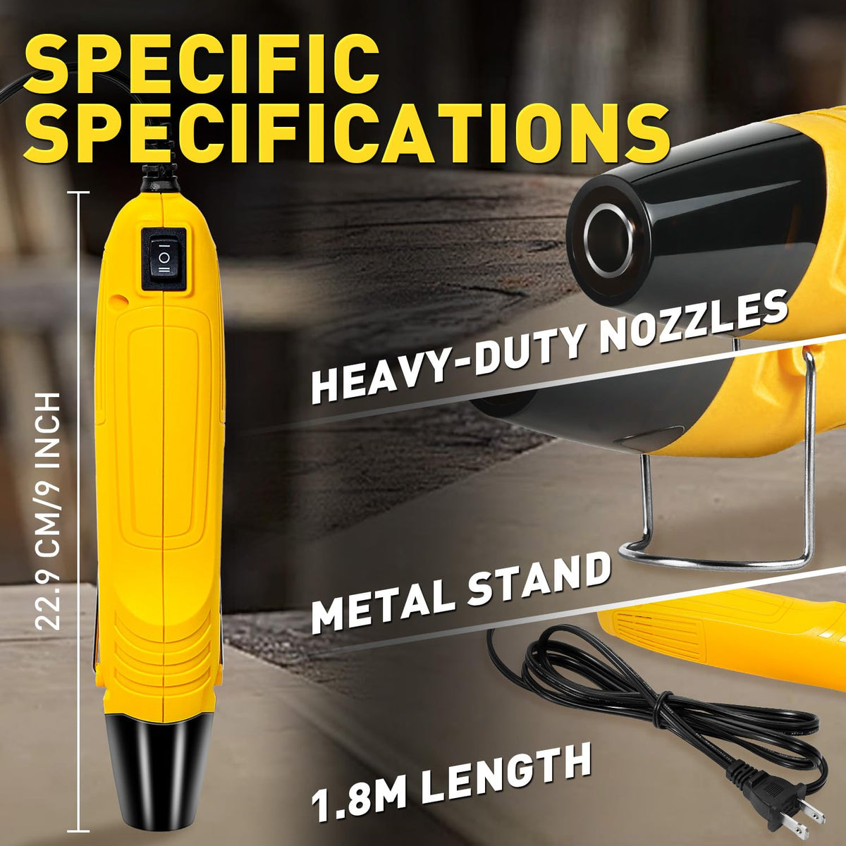
Check supply voltage and connector heating instructions. A gun's temperature setting is not the temperature of the joint.
Compare Waterproof Solutions → Match the complete repair system to the environment, not just the connector label.
Fix path 04 · wrong size / poor fit
Match both ends—not just the connector color.
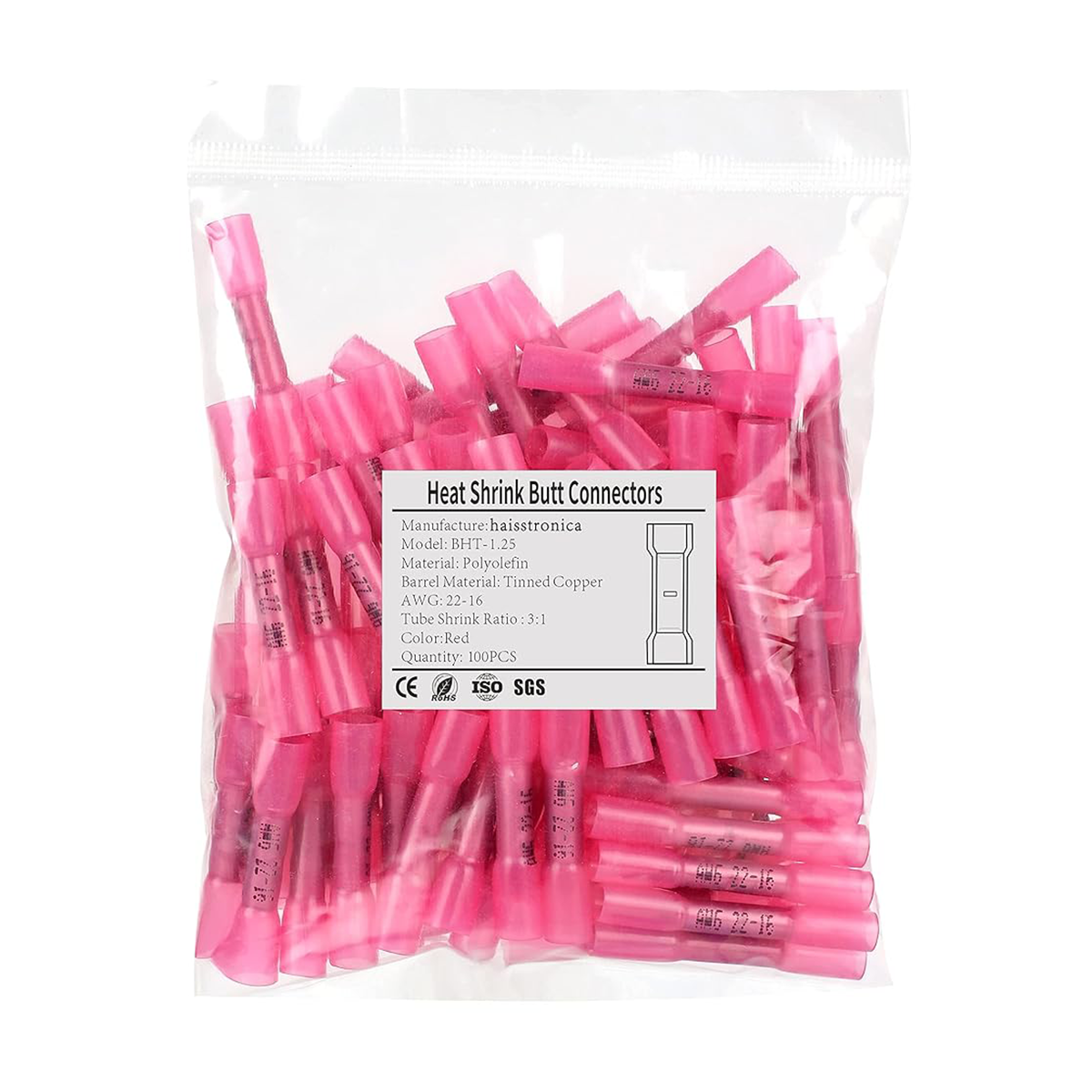
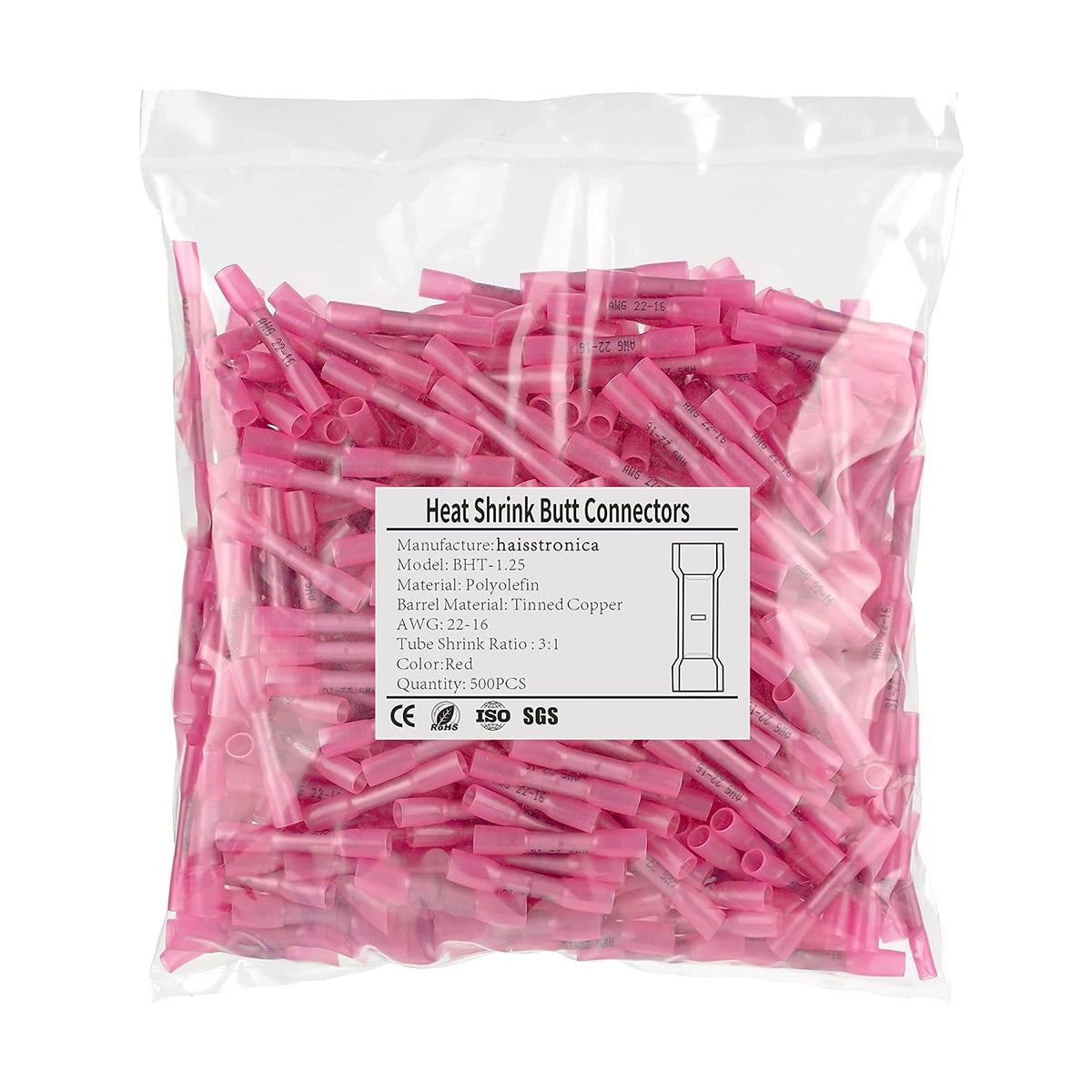
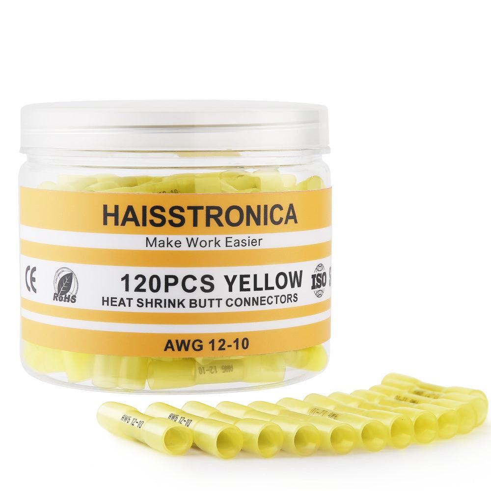
Read the actual AWG marking and permitted conductor construction. Color is a sorting aid, not a substitute for the product specification.
Choose a connector rated for the conductor. Do not fold the wire back or add filler strands unless the connector instructions explicitly allow that arrangement.
Select the correct size. Never remove strands to make it fit.
Use a splice specifically rated for that combination, such as an appropriate reducing splice. Do not assume one size will grip and seal both ends.
Confirm the sleeve's insulation-diameter range as well as the conductor range. Correct AWG alone does not establish a sealed fit.
Before cutting · complete repair checklist
Prepare the whole repair—not just a replacement connector.
Confirm conductor material, strand construction, AWG, jacket fit and environmental limits. Keep sufficient length for a supported repair.
Set the required strip length and verify clean stripping on a sample. A damaged wire end must be remade.
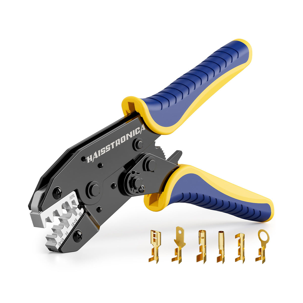
Confirm the exact terminal family and wire range. A kit containing smaller connectors does not extend the tool's rating.
Provide access around the entire sleeve and protect nearby components from heat. Keep flammable material and vapors away.
Prepare good lighting, the required mechanical/electrical checks and suitable cable supports. Use calibrated equipment where the job specification requires it.
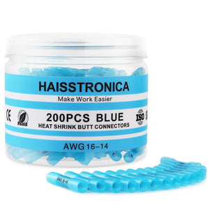
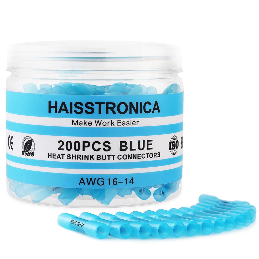
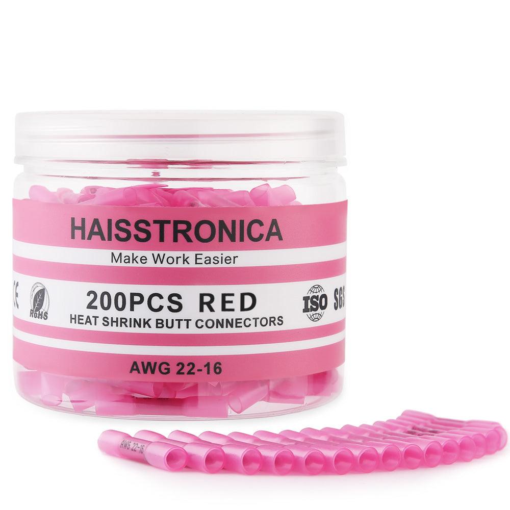
Need the core tool-and-connector pair? The AWG 22–10 crimper + connector set has a 200-piece butt-connector option. A stripper and heat gun are separate requirements; check your existing tools before ordering.
The remake sequence
Cut out the failed joint. Rebuild in this order.
-
Isolate the circuit
Disconnect the relevant power sources and verify the circuit is de-energized. Follow the equipment's shutdown and repair instructions.
-
Remove the failed splice
Cut beyond damaged or corroded conductor. If sound wire cannot be reached with enough slack, stop and replace the affected section using an approved method.
-
Confirm the replacement system
Match the connector, both conductors, insulation fit, die and exposure rating. Do not reuse the removed connector.
-
Strip to specification
Keep every strand intact. Insert to the specified depth without trapping insulation inside the conductor barrel or leaving unsupported bare wire.
-
Crimp each side and inspect
Place the barrel in the correct die position and complete the prescribed cycle. Inspect conductor capture and sleeve condition before sealing; carry out the required pre-seal retention check.
-
Recover the sleeve and let it cool
Apply controlled heat evenly using the product's sequence. Inspect adhesive contact and sleeve recovery at both ends. Keep the splice still while it cools.
-
Support, test and return to service
Prevent tension and repeated flex at the splice. Complete the application's mechanical, electrical and sealing checks before restoring power as directed by the equipment procedure.
Verification · no product shortcut
A neat sleeve is only the first inspection.
Mechanical retention
Use the force, method and acceptance criteria specified for the connector and application. A gentle hand check can reveal gross looseness but is not a calibrated pull test. Perform destructive pull testing on a representative sample—not a joint intended to remain in service.
Electrical performance
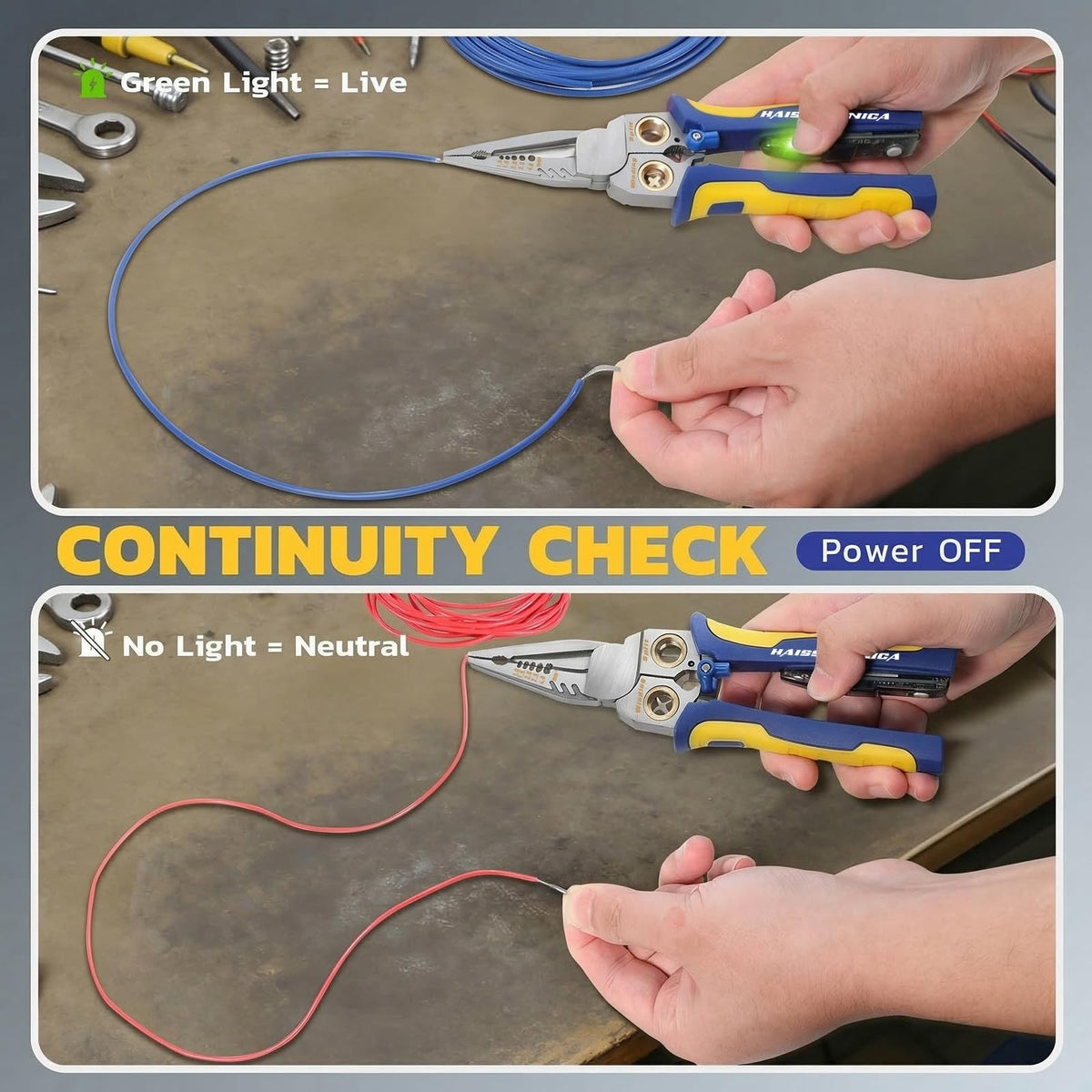
A continuity beep alone does not establish low resistance under load. Follow the equipment's test procedure; appropriately qualified personnel should evaluate load-related voltage drop or heating where required. Never use resistance mode on an energized circuit.
Seal integrity
Check recovery, adhesive contact, jacket condition and both cable exits. A visual check is not a waterproof certification. If water-ingress testing is required, use the approved method and acceptance criteria on a safe, de-energized test assembly; do not dunk an installed circuit as a home test.
Quality reference: TE Connectivity's crimp-quality guidelines emphasize matching wire, terminal and tooling and checking the applicable specification. They do not certify this repair or provide a universal force for every connector.
Common repair questions
What should you do when a splice fails?
Can I squeeze the old connector again?
Do not use repeated crushing as a repair for an unverified joint. Remove a failed connector, correct the cause and make a new splice following the specified process.
Will more heat fix a loose wire?
No. The heat-shrink sleeve is not a substitute for conductor capture in the metal barrel. Correct the crimp setup and replace the failed splice.
Why does corrosion return after I replace the connector?
Check for corrosion extending under the insulation, ongoing water entry, a sleeve that does not fit the jacket, incompatible materials or an unsuitable exposure rating. Replacing only the visible connector may leave the original cause in place.
Does one ratchet crimper cover every size in an assortment?
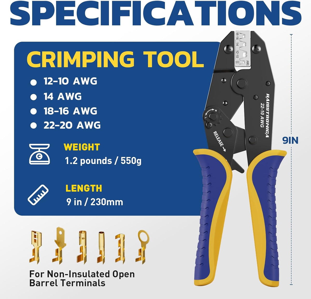
No. The linked connector assortment includes AWG 26–24, while the linked ratchet crimper is rated AWG 22–10 and the stripper AWG 24–10. Choose separately rated tools for smaller wire.
Can I use these connectors in any household or marine circuit?
No universal approval is implied. Fixed building wiring, safety-critical circuits and marine or equipment-specific repairs must follow their applicable requirements. Confirm the exact connector is allowed before installing it.
Further viewing: the demonstration linked in the original article. A demonstration does not replace the connector and equipment instructions.