
Measure First — Use the Barrel Depth Method
Why this works. The crimp’s gas‑tight zone is formed by the conductor barrel collapsing around the strands. If you under‑strip, strands don’t reach the full length; if you over‑strip, bare copper extends past the barrel (weak, corrodible). Standards back this approach: strip length and insulation position are process controls in NASA‑STD‑8739.4, and the brush length is a design target in Molex’s crimping guide.
Step‑by‑step (with simple tools):
Identify terminal & gauge. Confirm part family (e.g., insulated closed‑barrel ring, spade, or butt splice; open‑barrel/F‑crimp; ferrule). Find the AWG printed on the tongue or box. Many TE PIDG sheets include a strip‑length table—use it if available.
-
Measure the conductor barrel depth.
Use a set of calipers or a toothpick with a fine mark. Insert until it meets the barrel end wall; mark and measure.
That dimension ≈ target strip length. For some families the spec adds a small brush; follow the table if provided.
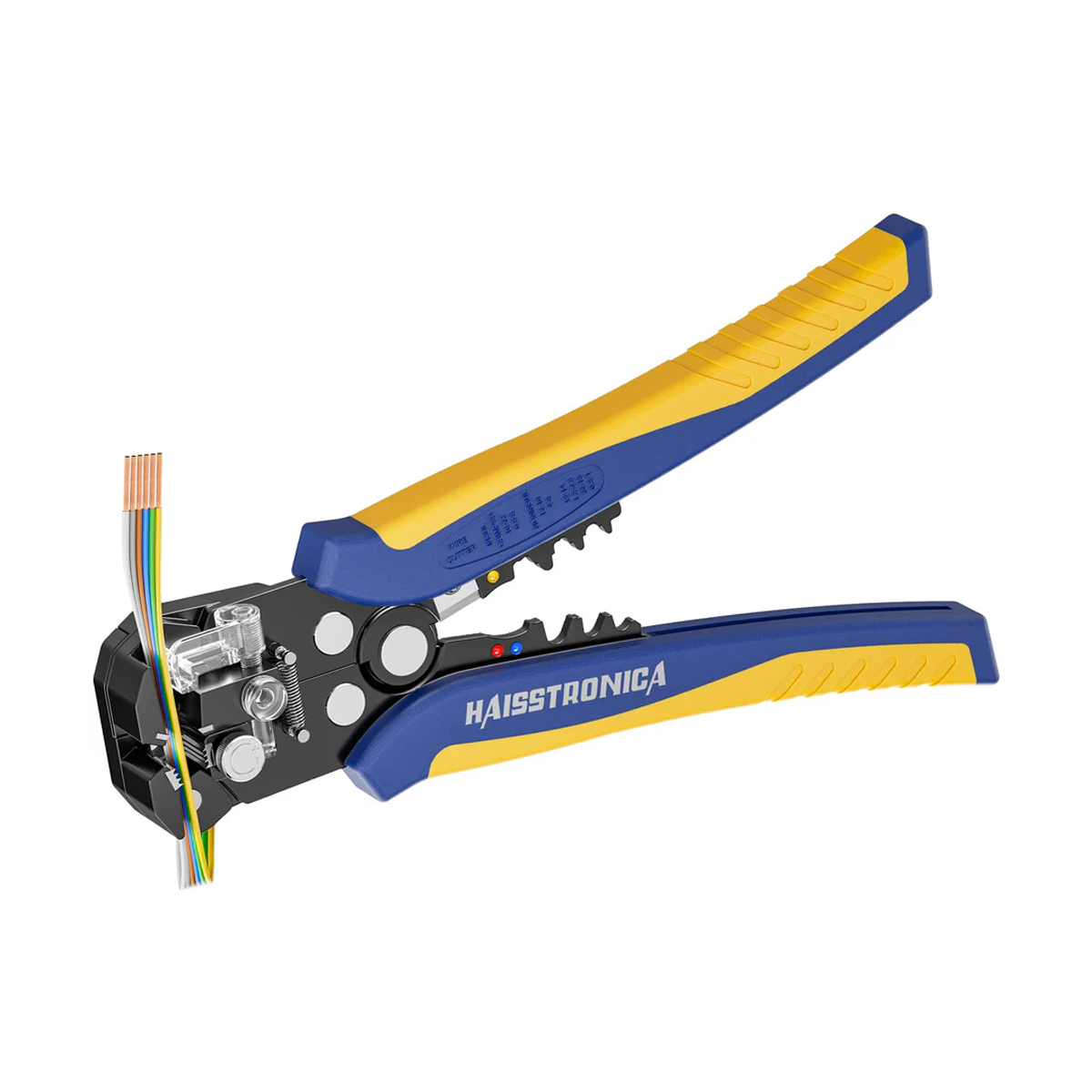
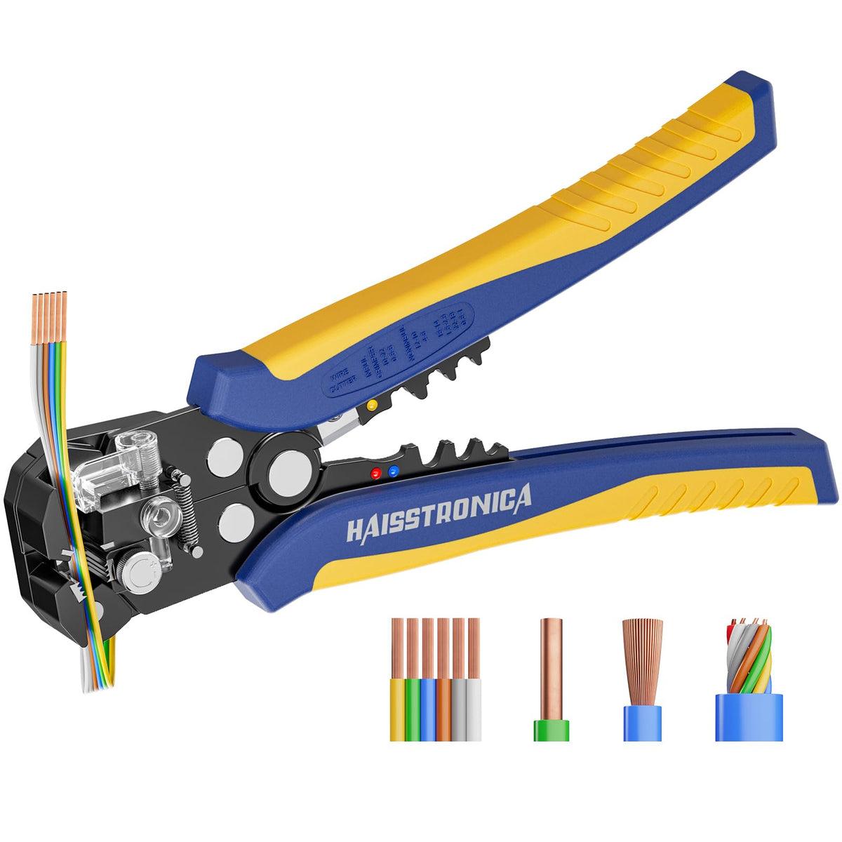
Cut and strip cleanly. Use a self‑adjusting or calibrated wire crimping tool’s stripper. No nicks; NASA calls out nick‑free stripping and defines acceptable insulation clearance (see 10.1.4 in the standard).
Dry‑fit. Insert the conductor; the copper should fully fill the conductor barrel with insulation touching the barrel entrance so the insulation support can crimp the jacket (on insulated styles).
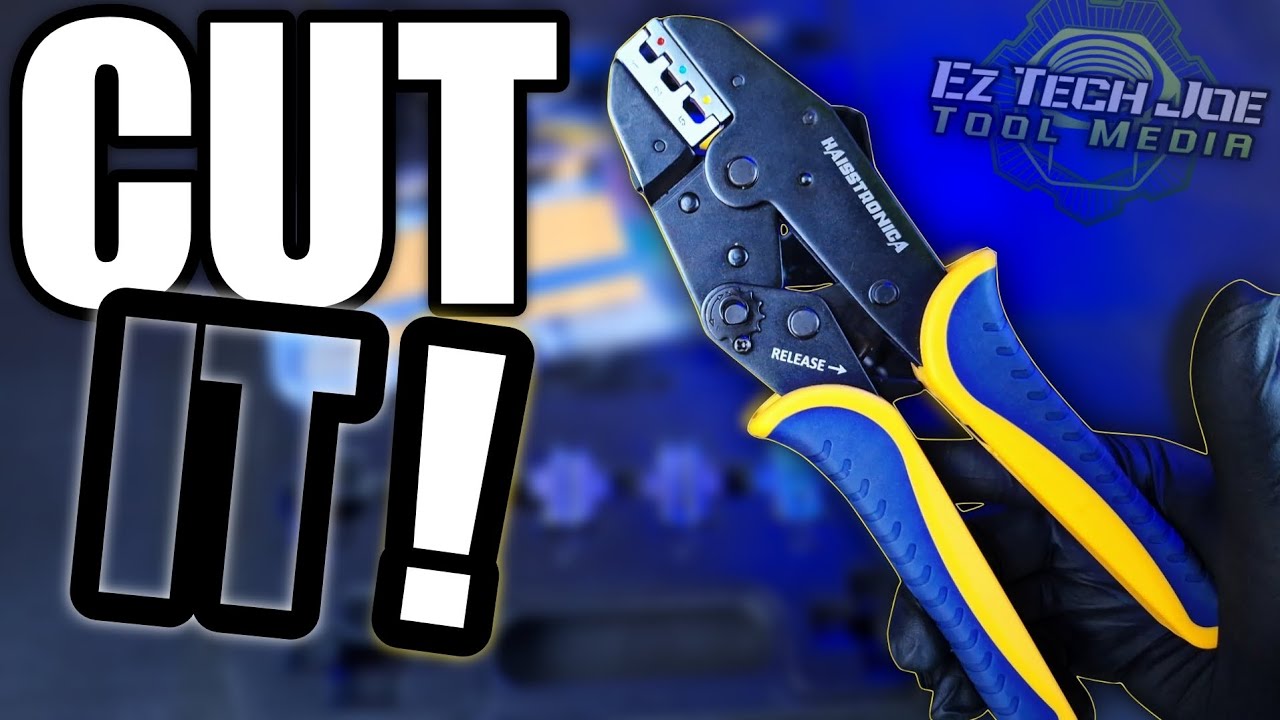
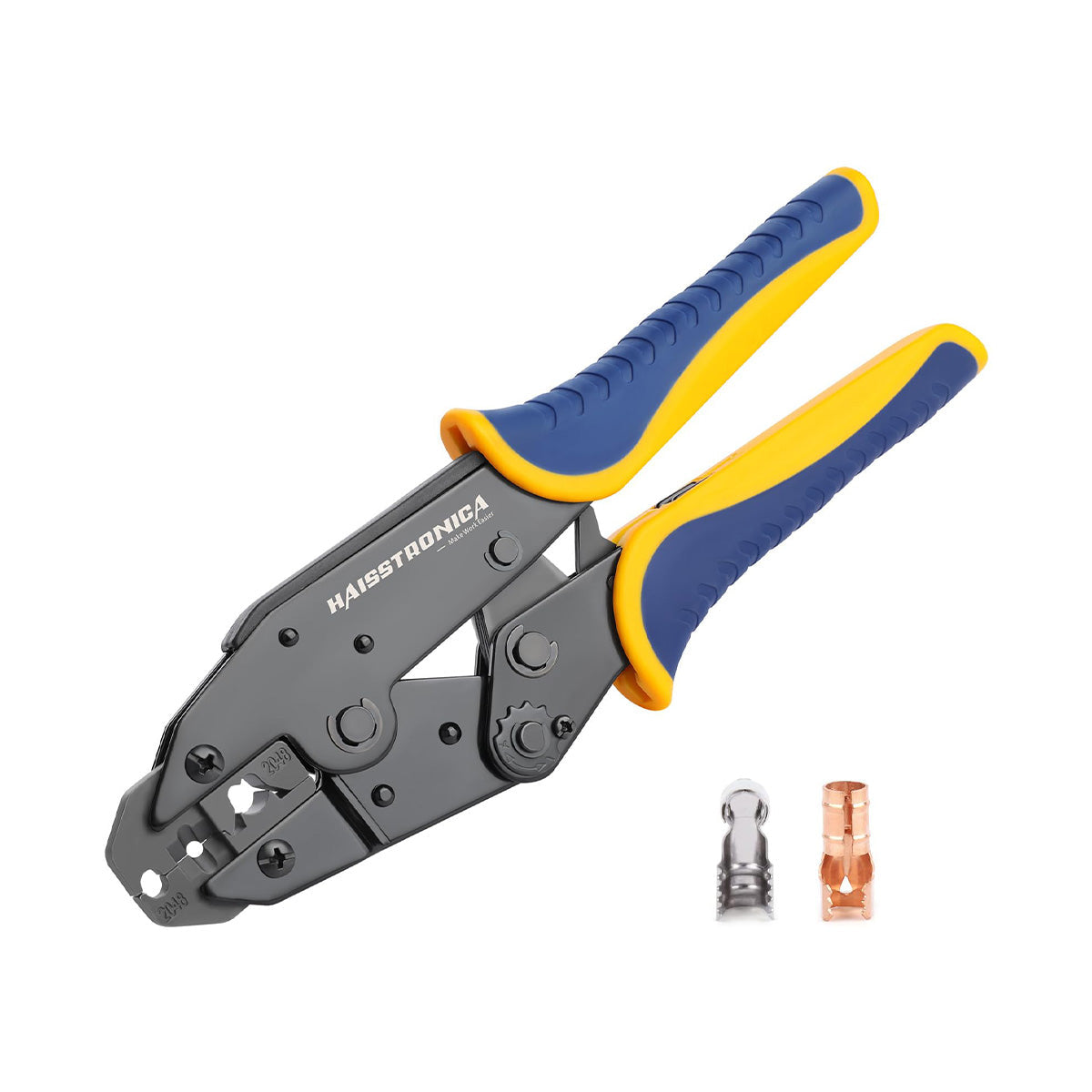
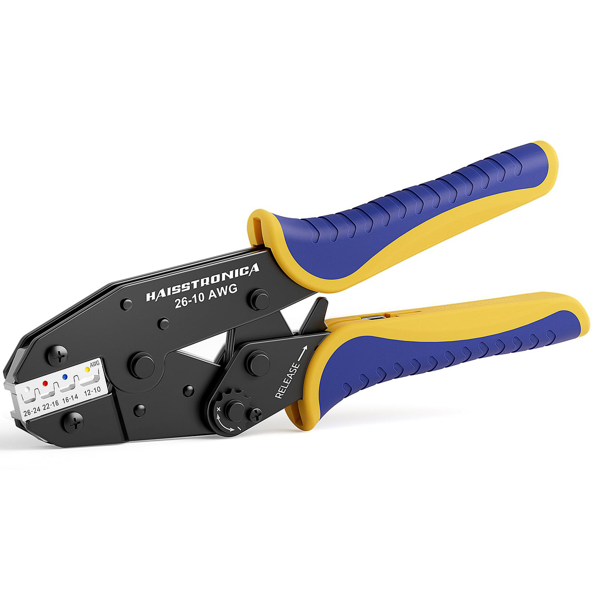
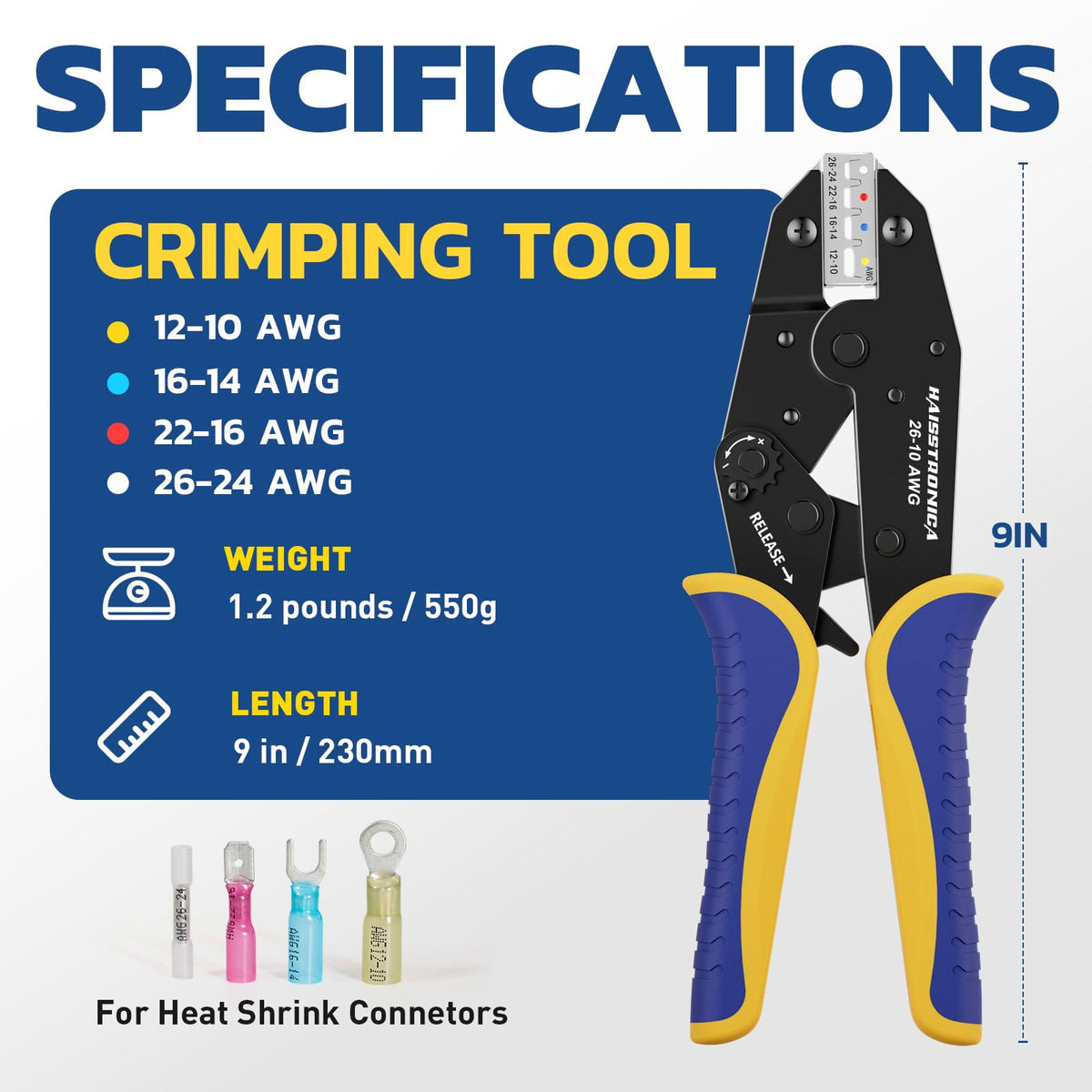
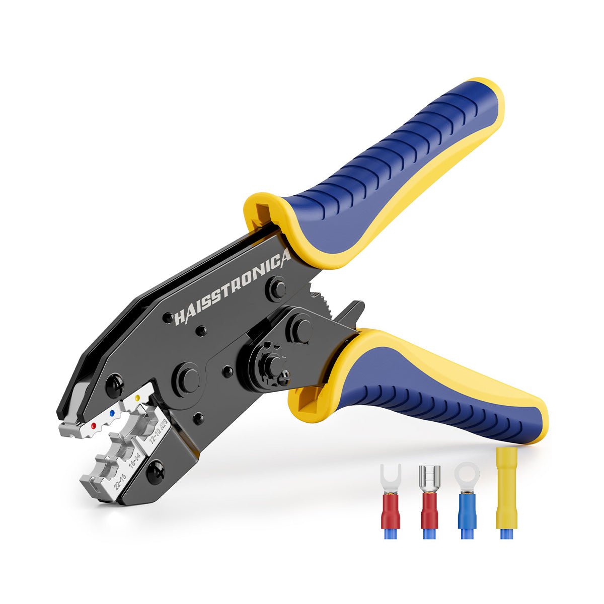
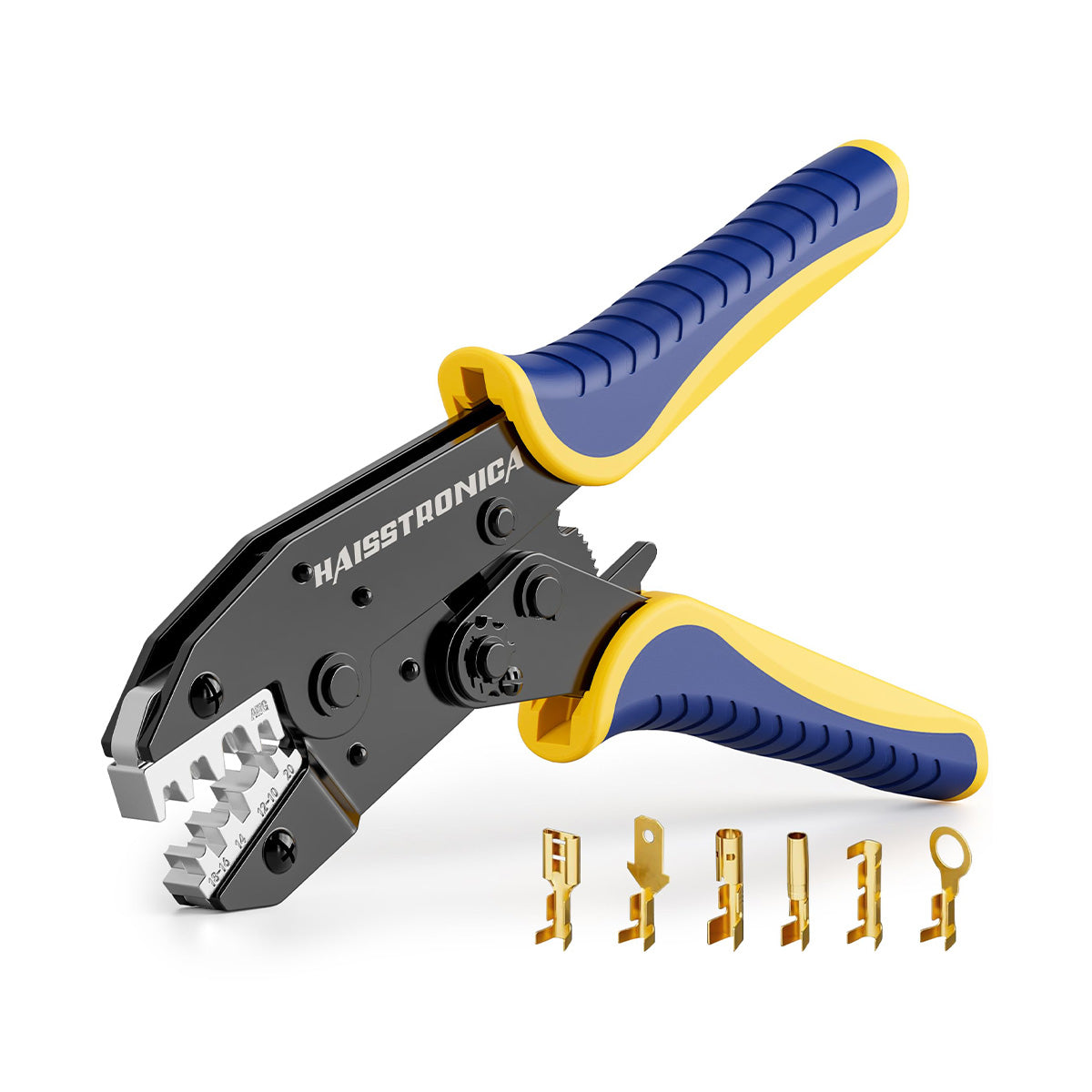
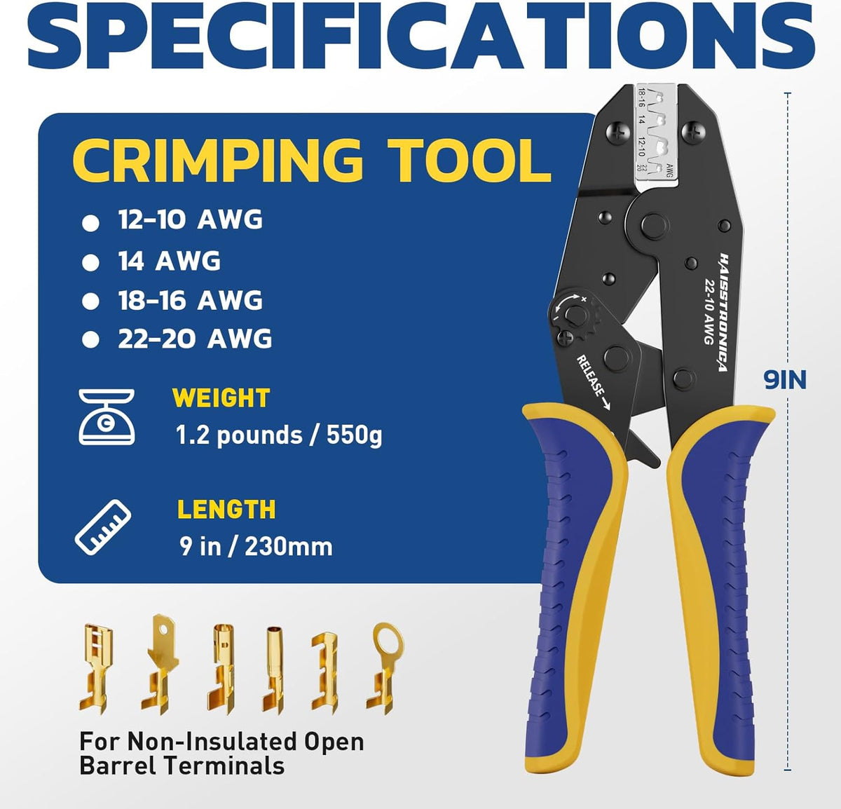
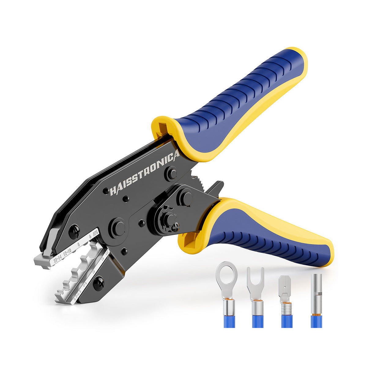
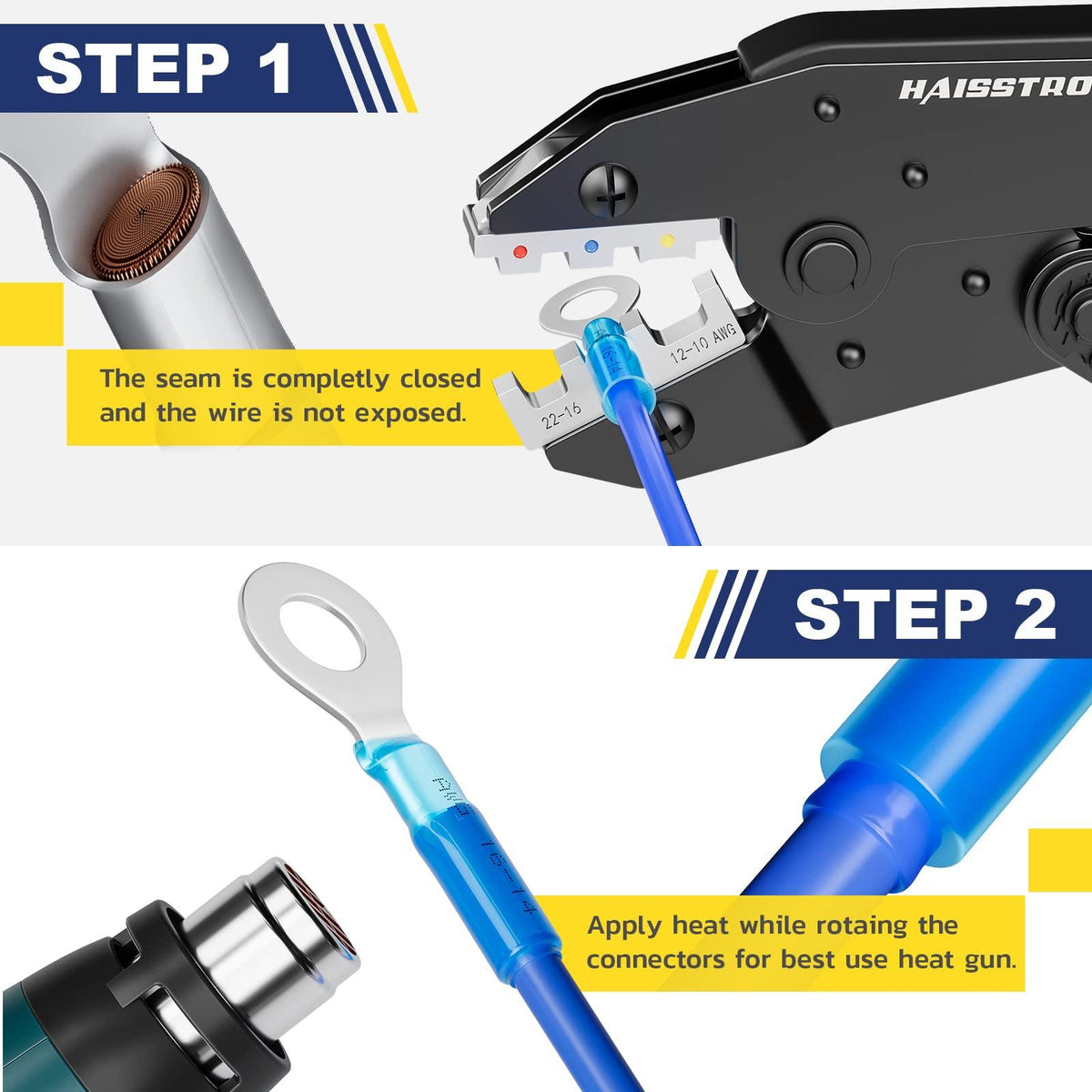
Crimp with matched dies. Use the die size that matches the AWG and terminal type. Ratcheting crimper tool frames help maintain force and release only at the correct compression.
Quick QA checks:
You can see (or feel) conductor at the barrel end—no voids and only a small brush visible (per the maker’s spec).
The insulation is captured by the insulation support (if present) and meets the insulation clearance limits noted in NASA‑STD‑8739.4.

Connector-by-Connector Details
Different terminals expect different strip lengths and insulation positions. Use these patterns plus the datasheet.
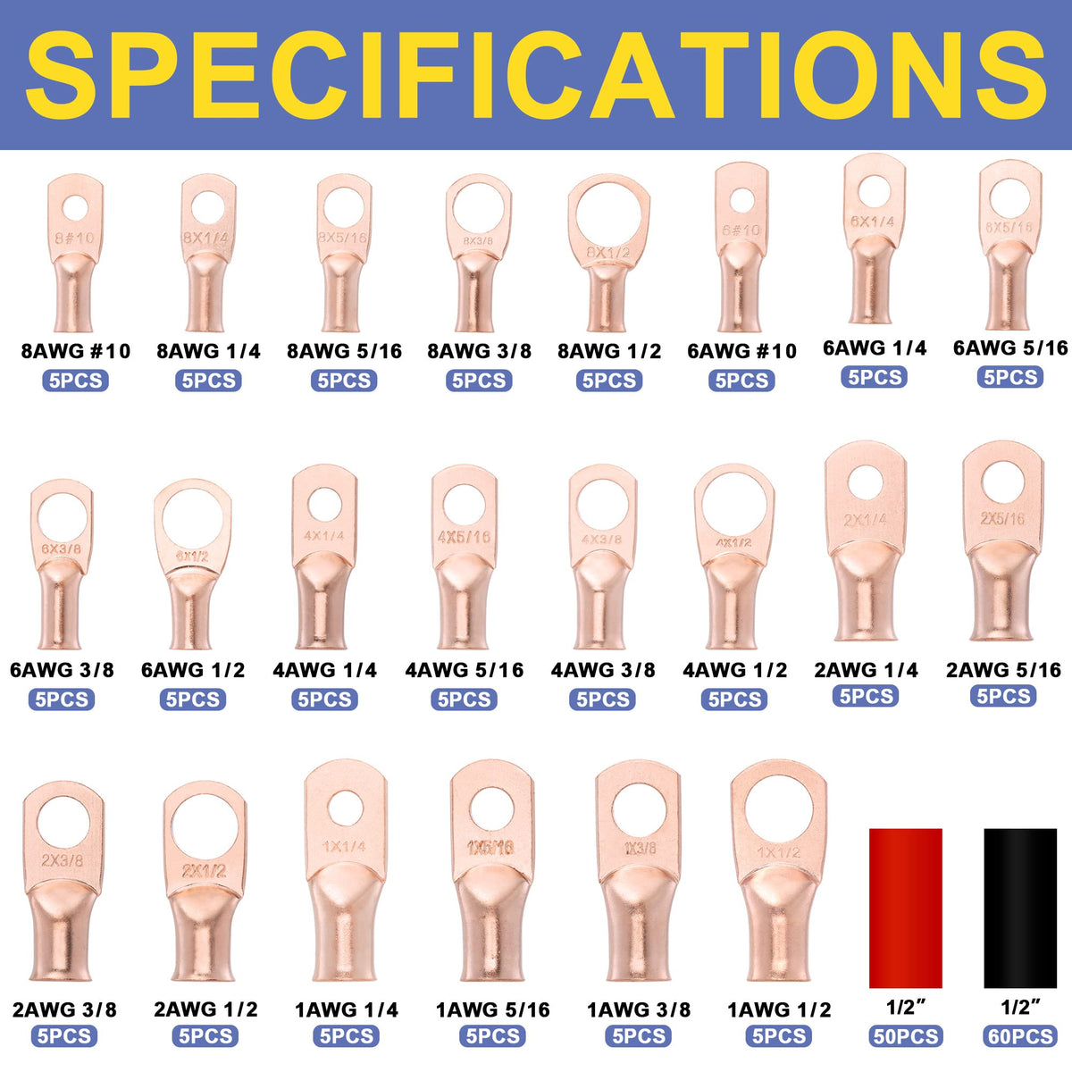
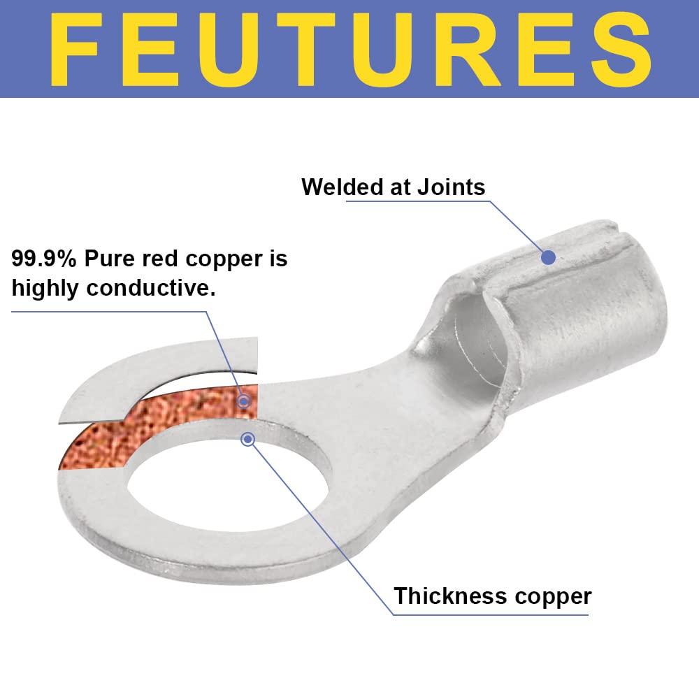
1) Insulated, closed‑barrel (ring/spade/quick‑disconnect)
Typical strip range (22–10 AWG): ~7.5–9.1 mm for TE’s PIDG family; see the product’s spec for exact values. The insulation should butt against the conductor barrel and be captured by the insulation support.
Why: Fills the barrel for a gas‑tight crimp while leaving only a tiny conductor brush.
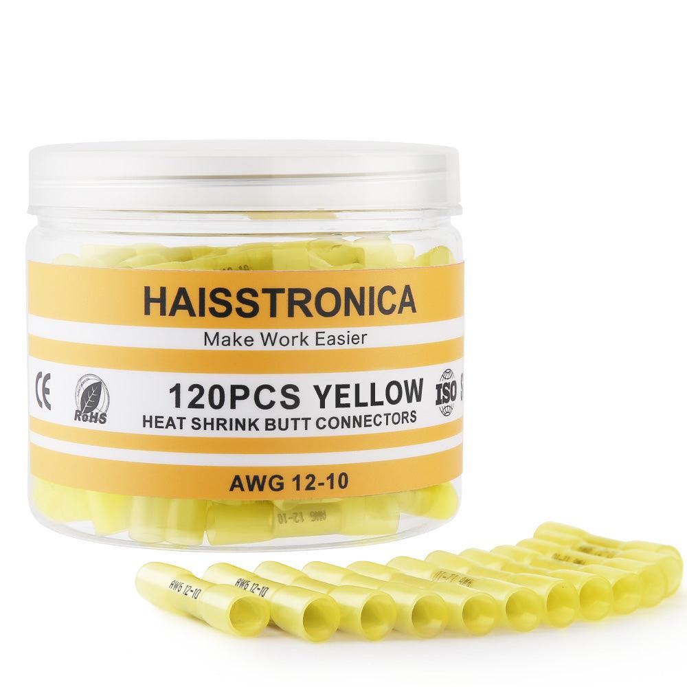
2) Butt splices (insulated or heat‑shrink butt)
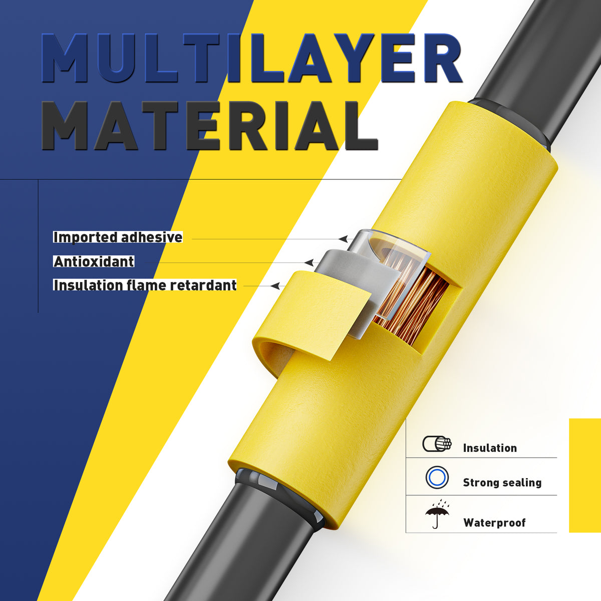
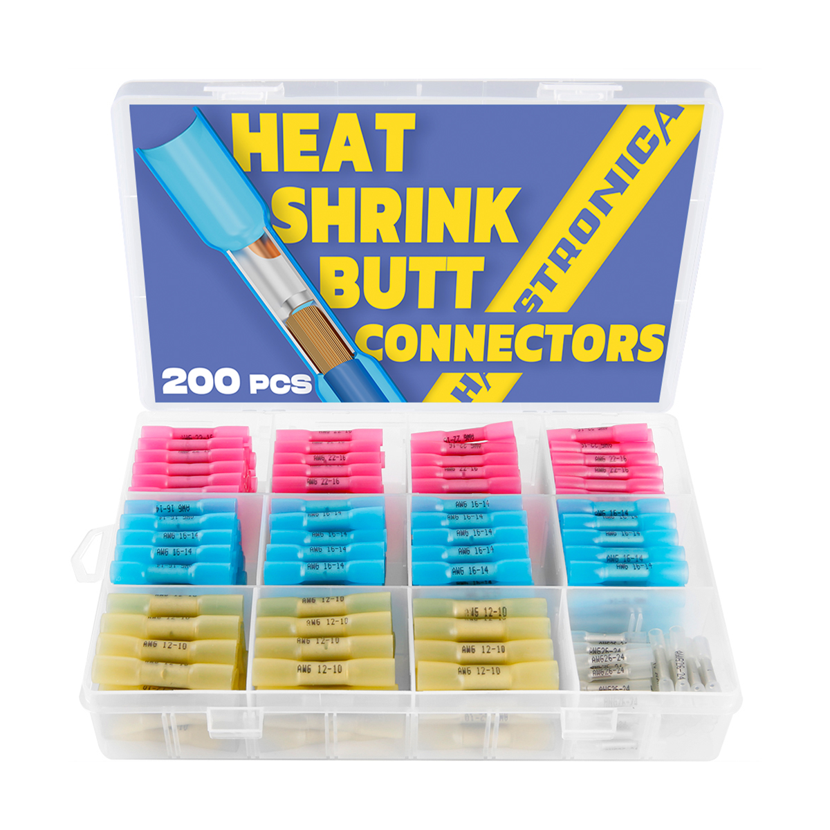
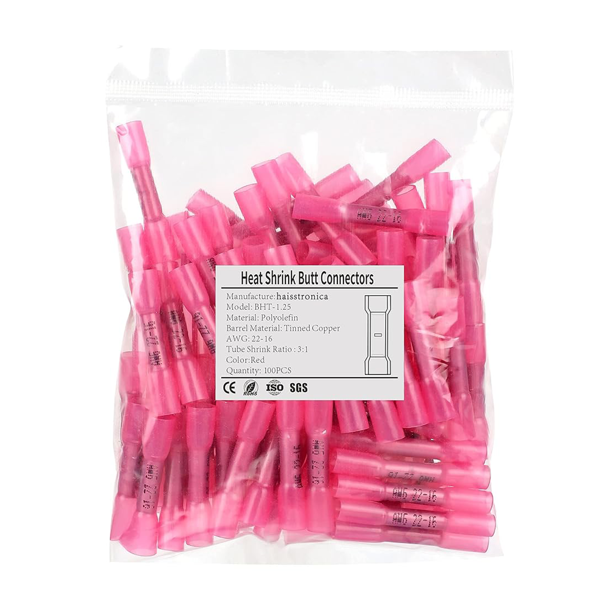
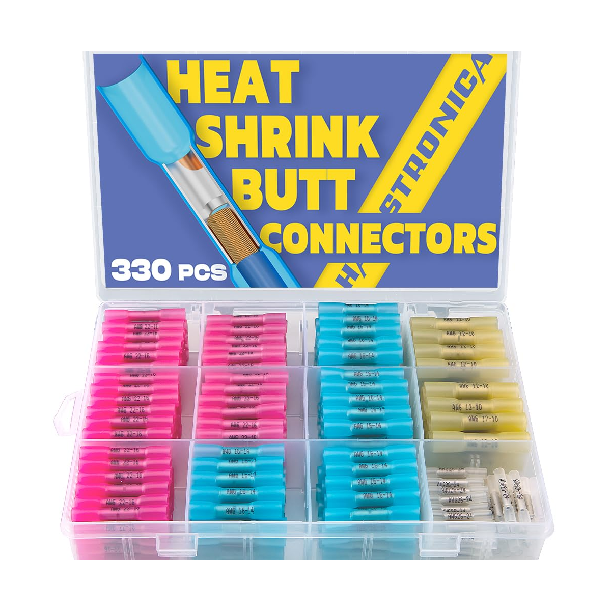
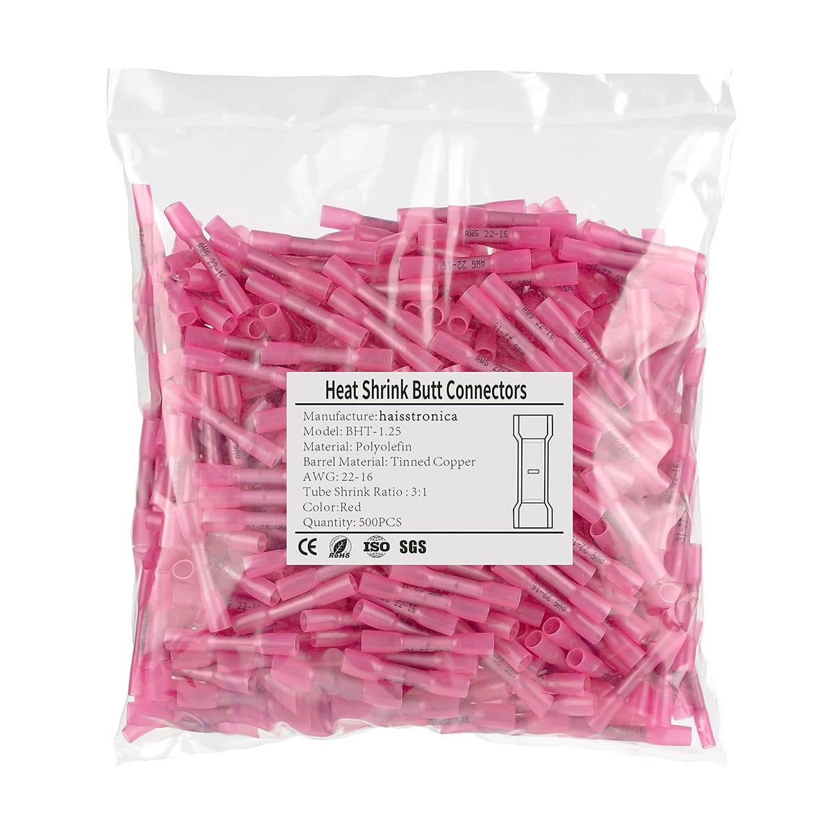
Strip each side to its barrel depth; insertion marks help ensure symmetry. Crimp before heat shrinking when using heat‑shrink butt connectors (3M states shrink is an installation step after crimp).
Why: Equal penetration on both sides centers the splice slug and maximizes tensile strength.
3) Open‑barrel / F‑crimp (automotive “stamped & formed”)
Strip short—just the conductor barrel length (often a few millimeters) so the conductor brush is controlled and the insulation support tabs bite the jacket behind it. Makers (Molex, TE, Yazaki) say strip length sets brush length and is specified per series; always consult the terminal spec.
4) Wire ferrules
Strip to the metal sleeve length (not including the plastic collar). The strands should fill the sleeve with no copper exposed beyond the ferrule tip after crimp. IPC/NASA workmanship references emphasize no nicked strands and proper insulation support behind the ferrule.
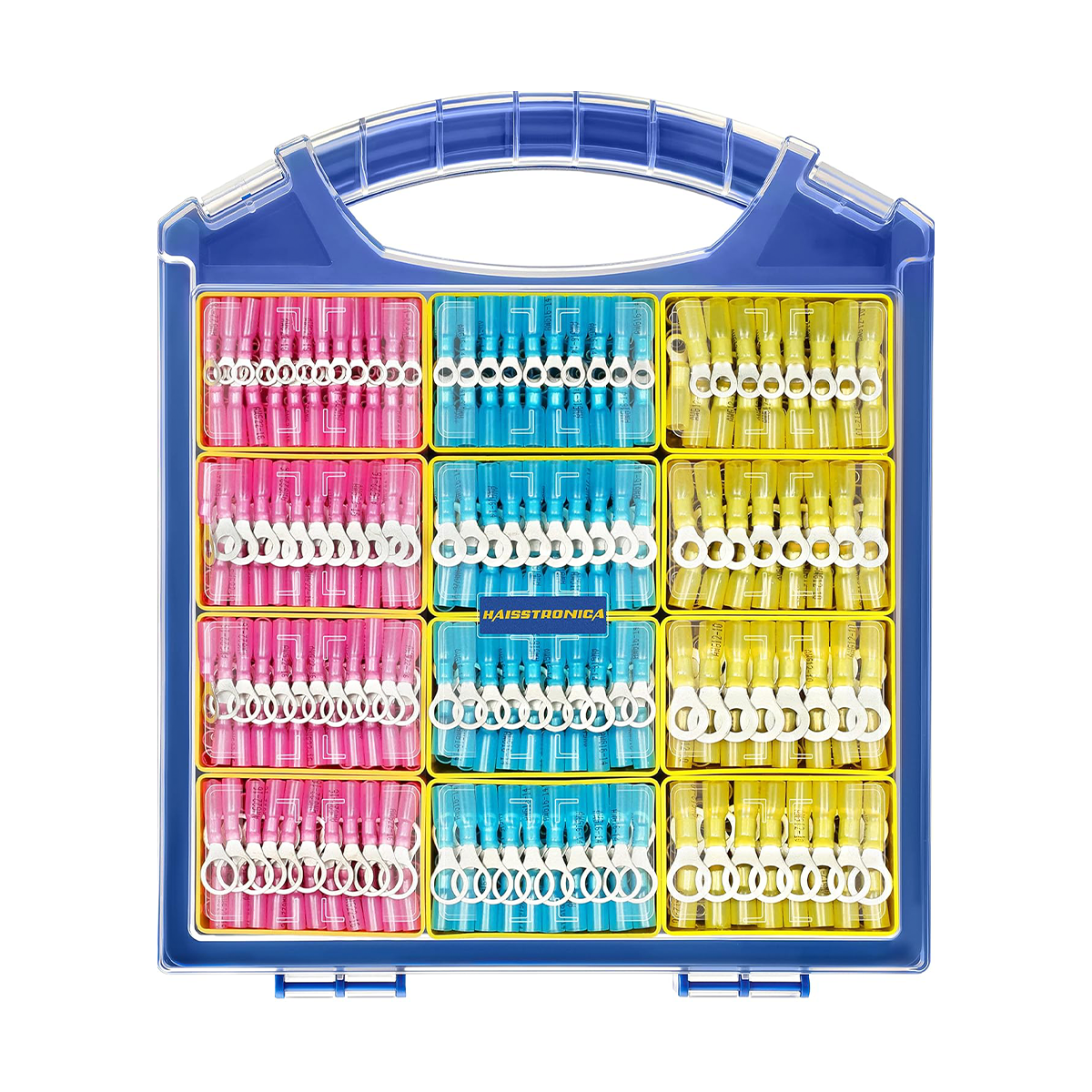
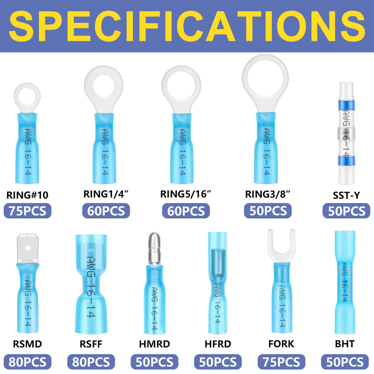
5) Heat‑shrink terminals (ring/spade/butt with adhesive‑lined tubing)
Strip per the terminal table (often the same as the non‑shrink version). After crimping, heat until the solder/adhesive (if present) flows and tubing fully recovers per the product’s instruction.

Barrel Depth Method at a Glance
Calipers or a depth gauge: measure conductor barrel length.
Strip to that length (± the small brush allowed by the spec).
Insert so insulation butts the barrel entrance.
Crimp with the right die; ratcheting wire crimping tool helps ensure full compression.
Inspect: tiny bellmouths, centered crimp, correct insulation capture, small/no brush beyond the barrel; perform a quick pull test per your shop’s procedure. High‑reliability standards treat strip length and insulation clearance as controlled parameters.
FAQs
Is there a universal strip length? No—follow the terminal family’s spec. TE PIDG 22–10 AWG shows ~7.5–9.1 mm; other families differ.
How do I know I didn’t over‑strip? You shouldn’t see long bare copper beyond the conductor barrel; only a controlled brush if the spec permits.
What if I nick a strand while stripping? Cut back and re‑strip. Nicked strands are a reject per workmanship standards.
Conclusion
Great crimps start before you pull the handle: pick the correct terminal, measure the barrel, and strip just enough insulation to fill it—nothing more. That one choice controls brush length, tensile strength, and contact resistance. Cross‑check against the datasheet, keep your wiring crimpers calibrated, and perform a quick visual + pull test. You’ll build cool‑running, low‑resistance joints that last.







1 commentaire
yan
Dear Sir,
Wire strip length of 16-14, 0.205 × 0.032, female disconnect?
Thanks.
Dear Sir,
Wire strip length of 16-14, 0.205 × 0.032, female disconnect?
Thanks.