At 150°C+, documentation comes before product selection
Measure the connector’s real operating temperature, then verify the continuous and peak ratings of every component in the connection. If any rating is missing or lower than the measured condition, do not use that product.
Measure continuous heat
Record peak heat + duration
Check every component rating
Select compatible materials
Make the matched crimp
Load-test and trend heat
Start with the temperature at the connection—not ambient alone
Air temperature is only one input. Resistance at the joint, current, nearby heat sources, enclosure airflow and duty cycle can make the conductor or terminal hotter than the surrounding air.
- Measure at the connector body and conductor. Record the stabilized temperature at normal maximum load.
- Capture peaks. Note the peak temperature, how long it lasts and how often it repeats.
- Add design margin. Do not design a connection to operate continuously at the exact published limit.
- Repeat after installation. Routing, bundling and enclosure changes can alter the final temperature.
Do not proceed until all four answers are “yes”
- The wire insulation has a documented continuous-use rating above the measured conductor temperature.
- The terminal or connector system is rated for the same conductor size, current and temperature.
- Any sleeve, adhesive, seal, housing or boot is independently rated for the exposure.
- The published peak-temperature allowance covers the actual peak duration and cycle count.
Missing data is not approval. At 150°C+, route the design to the equipment manufacturer, connector manufacturer or a qualified electrical engineer.
The lowest-rated component sets the system limit
| Check | Failure risk | Evidence required |
|---|---|---|
| Wire insulation | Softening, cracking or loss of dielectric strength | Wire datasheet and temperature class |
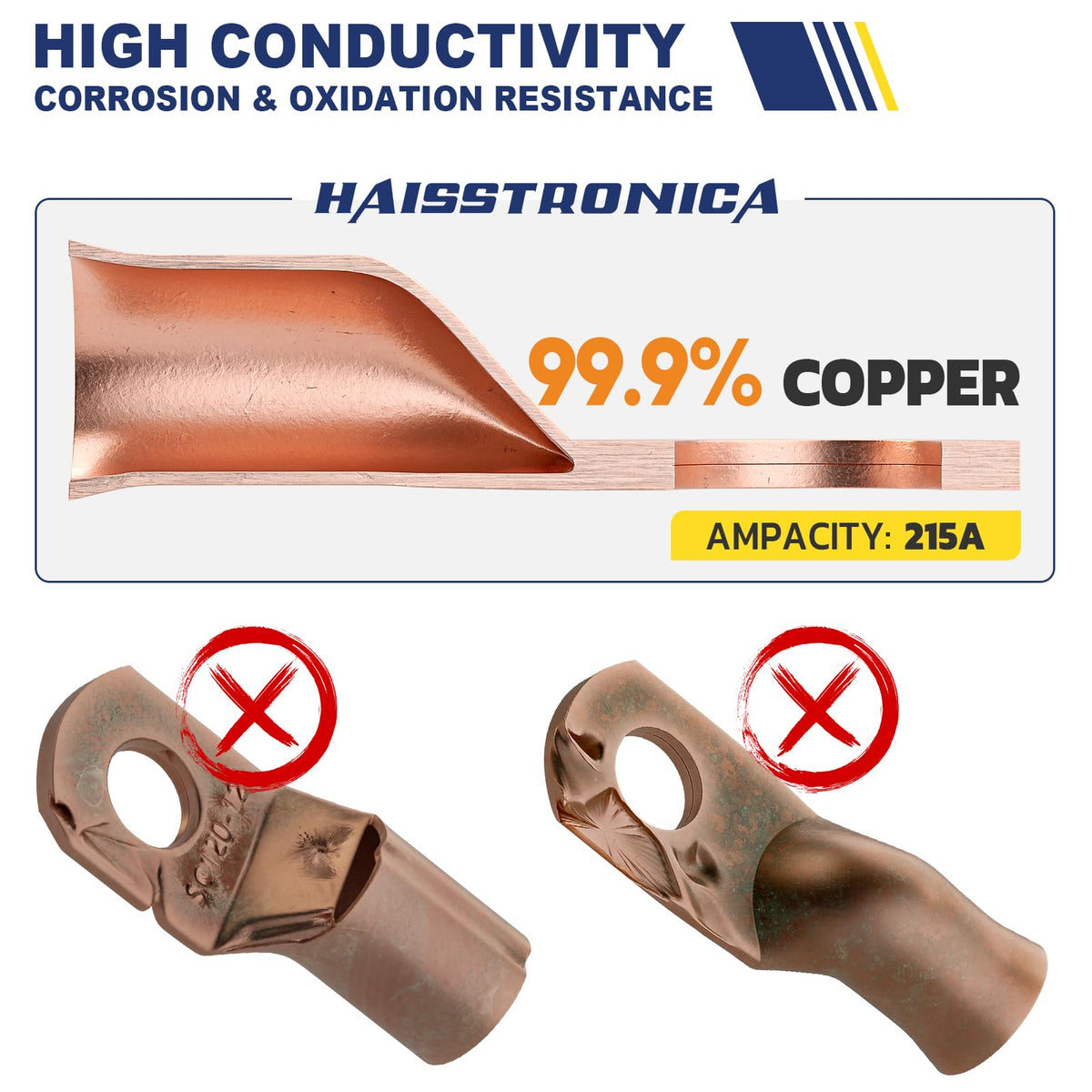
| Terminal + plating | Oxidation, relaxation or rising contact resistance | Terminal manufacturer’s current and temperature limits |
| Tubing + adhesive | Brittleness, adhesive flow or loss of sealing | Continuous and short-term temperature ratings |
| Solder or seal ring | Creep, remelt or loss of mechanical support | Connector-system datasheet for the exact part |
Why generic solder-seal connectors are not the default at 150°C+
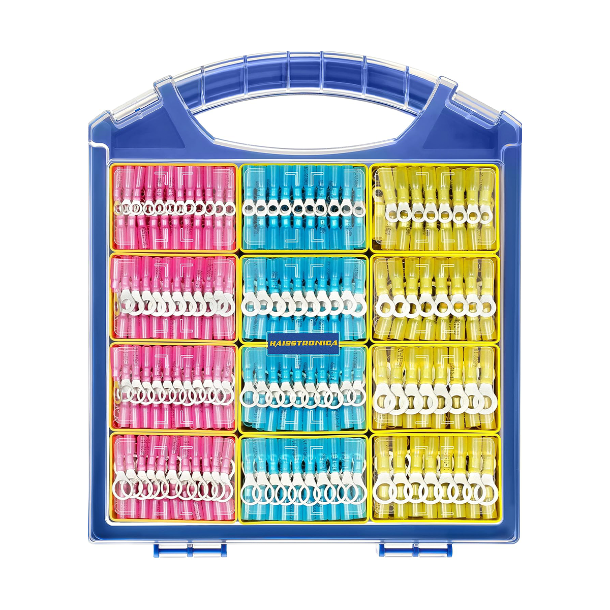
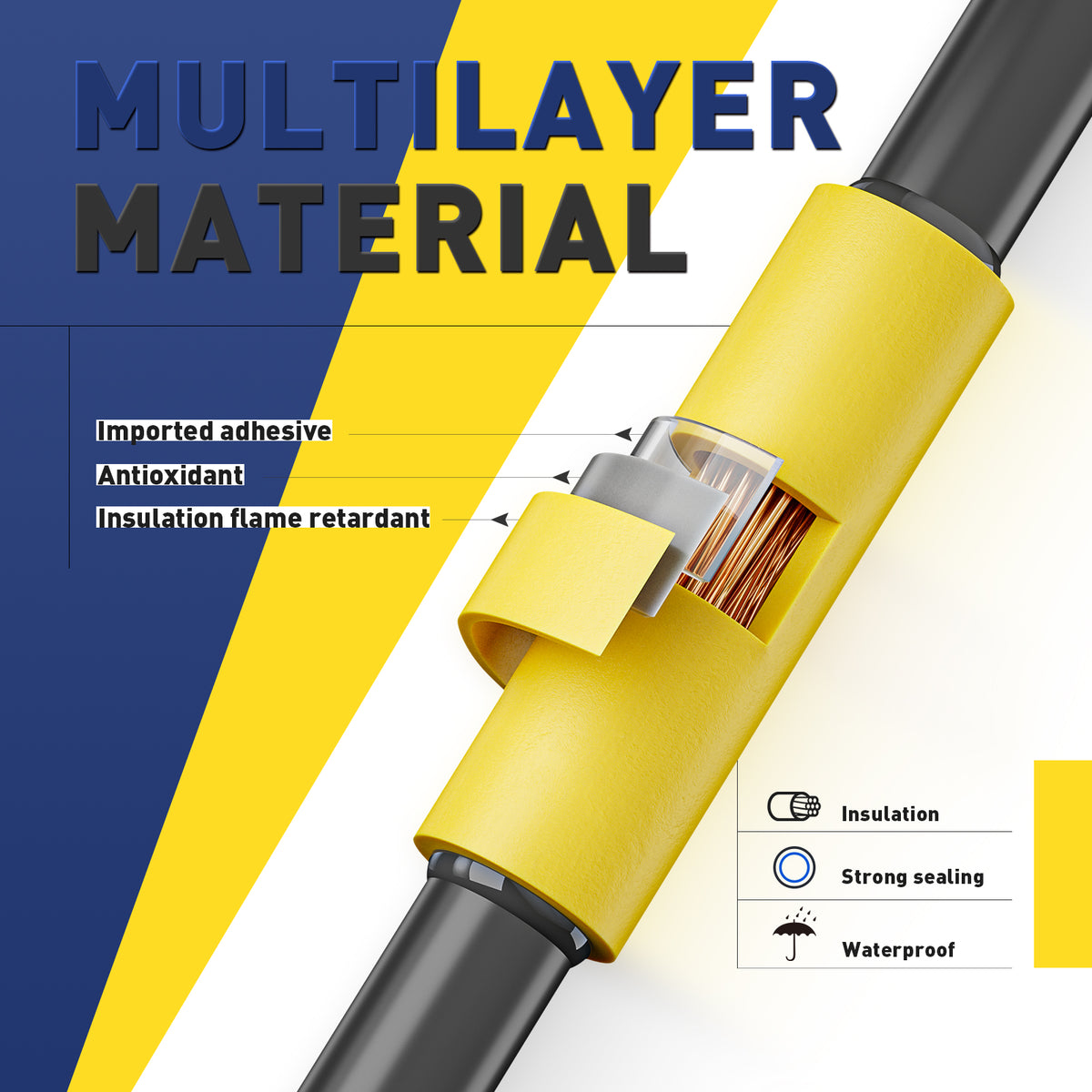
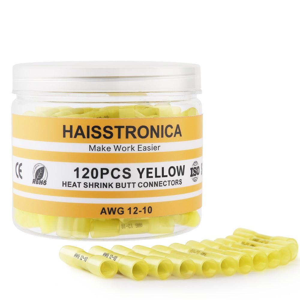
A solder-seal splice contains more than metal: the sleeve, adhesive and solder formulation can each become the limiting component. Unless the exact connector has a published rating for the measured continuous temperature, peak profile, wire size and environment, choose a documented industrial high-temperature connection system instead.

Choose the connection only after the rating passes
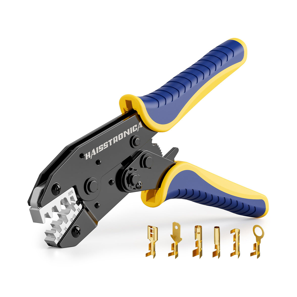
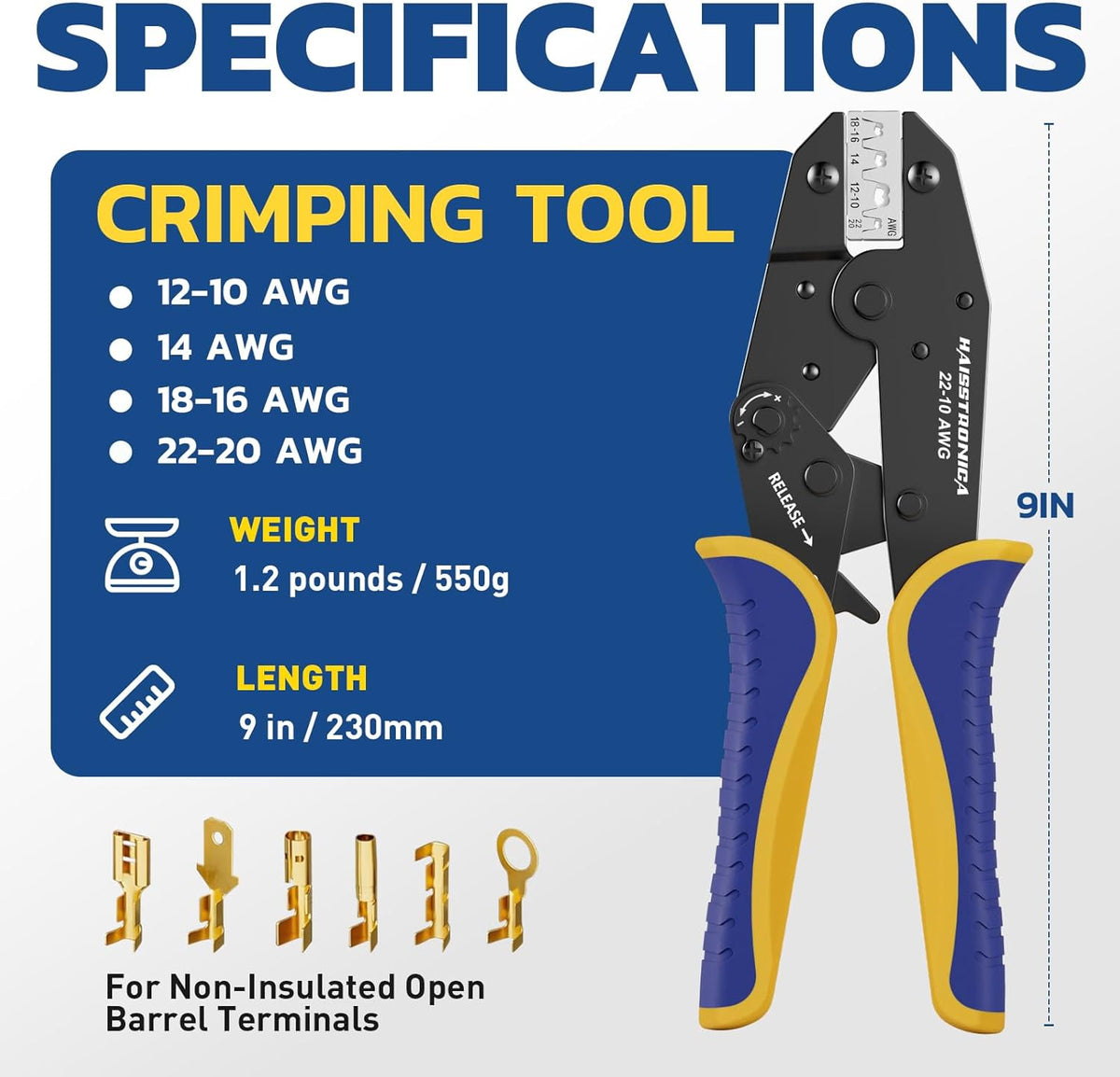
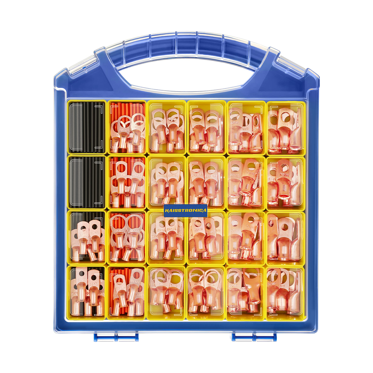
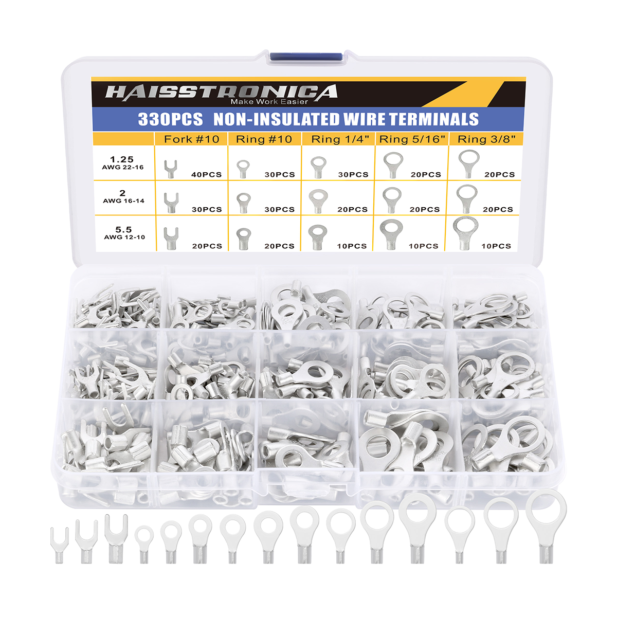
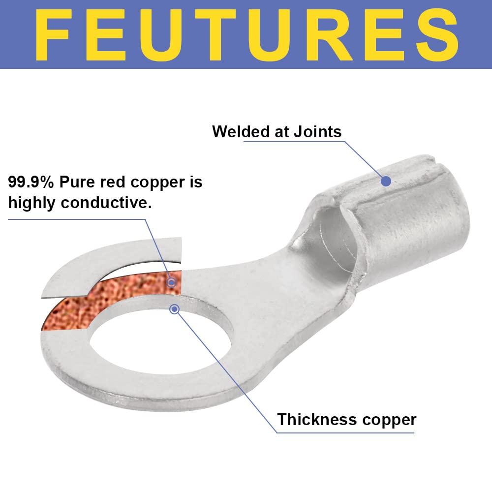
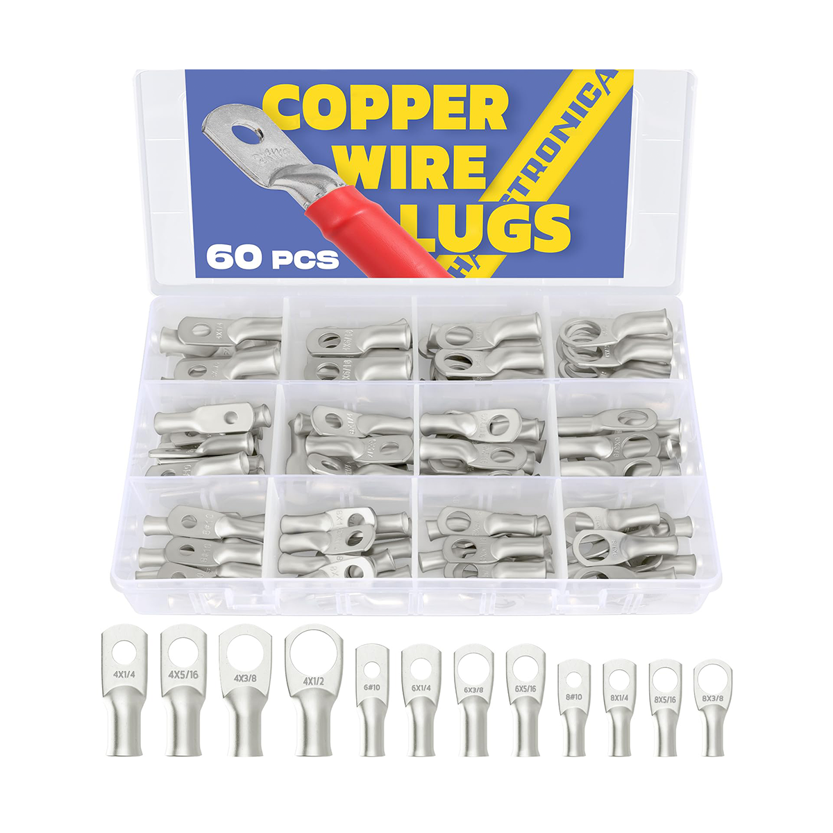
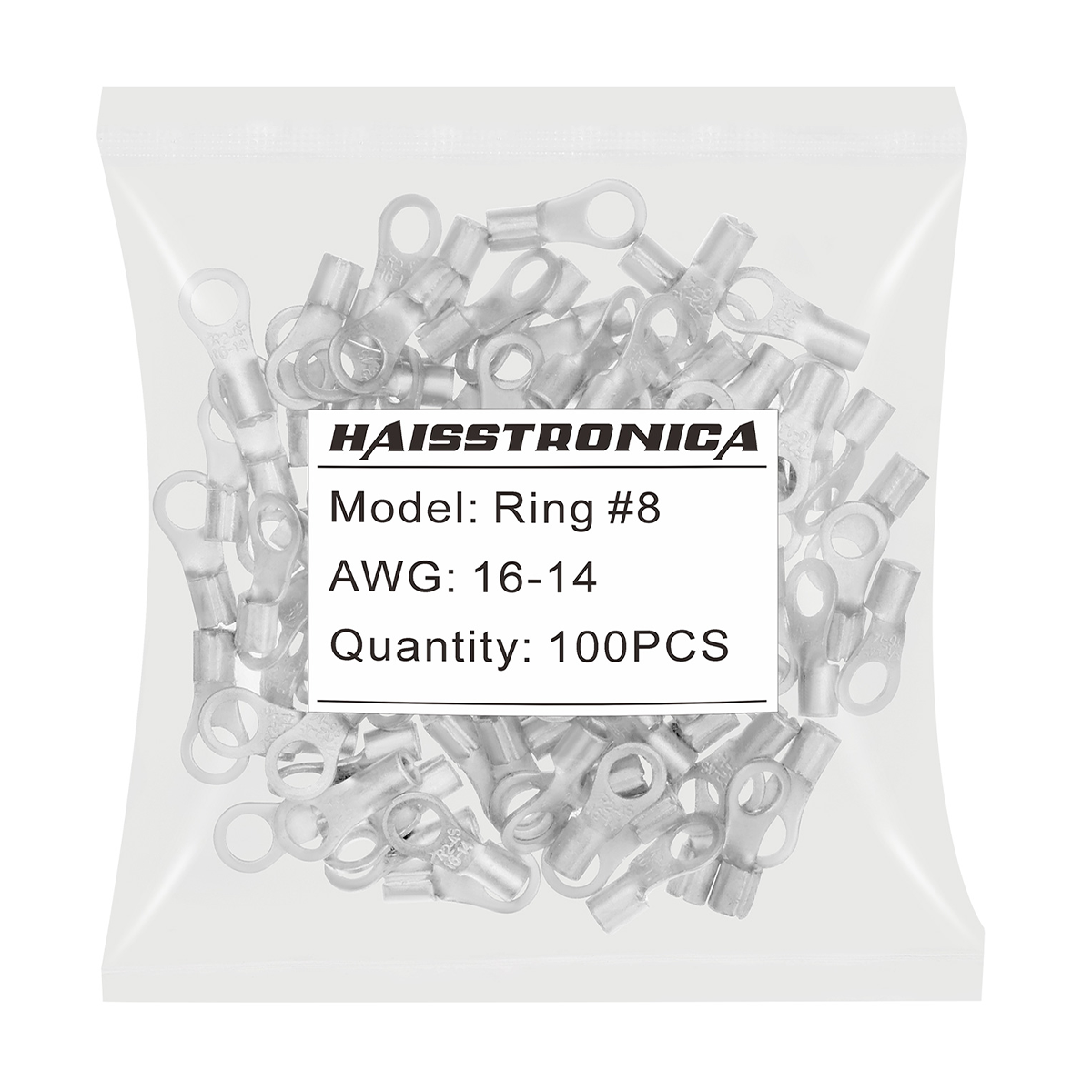
Matched non-insulated terminal
Use only when the exact terminal, conductor, current and environment are covered by manufacturer documentation.
Review terminals + verify rating →Stop and specify an industrial solution
Do not substitute a general automotive or DIY connector. Obtain the exact material, certification and derating data first.
Make the crimp without adding a new failure mode
- Confirm conductor material, strand class and cross-section match the terminal.
- Strip to the specified length without nicking or removing strands.
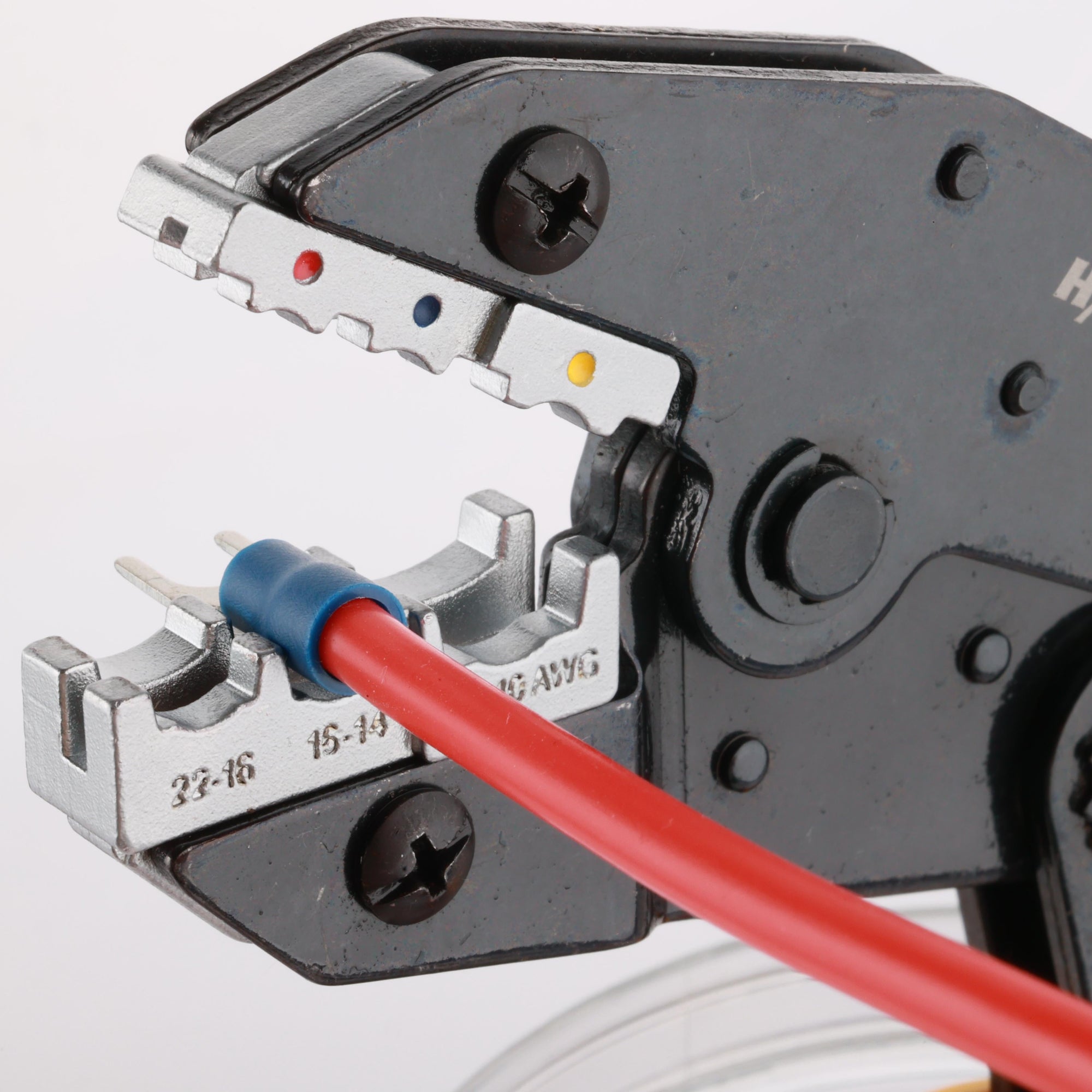
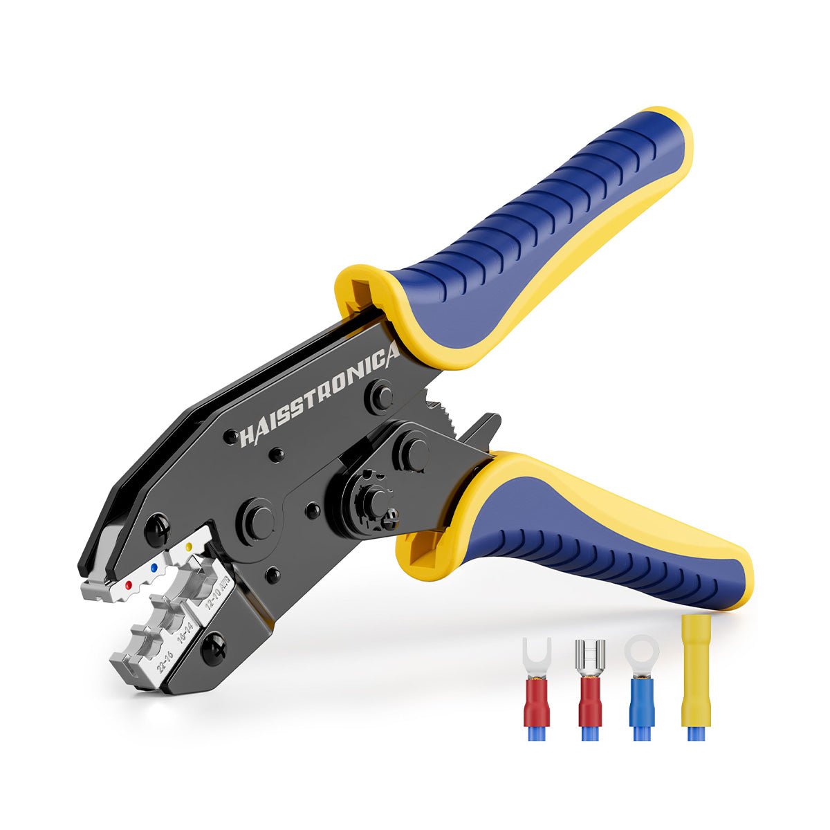
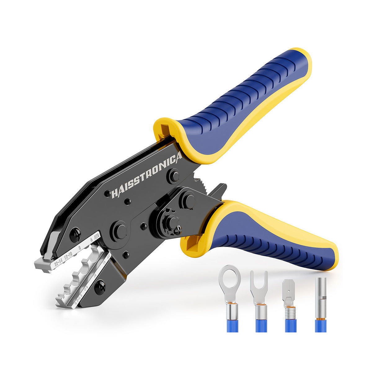
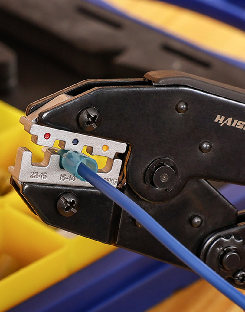
- Use the die profile and cavity specified for that terminal—not a visually similar cavity.
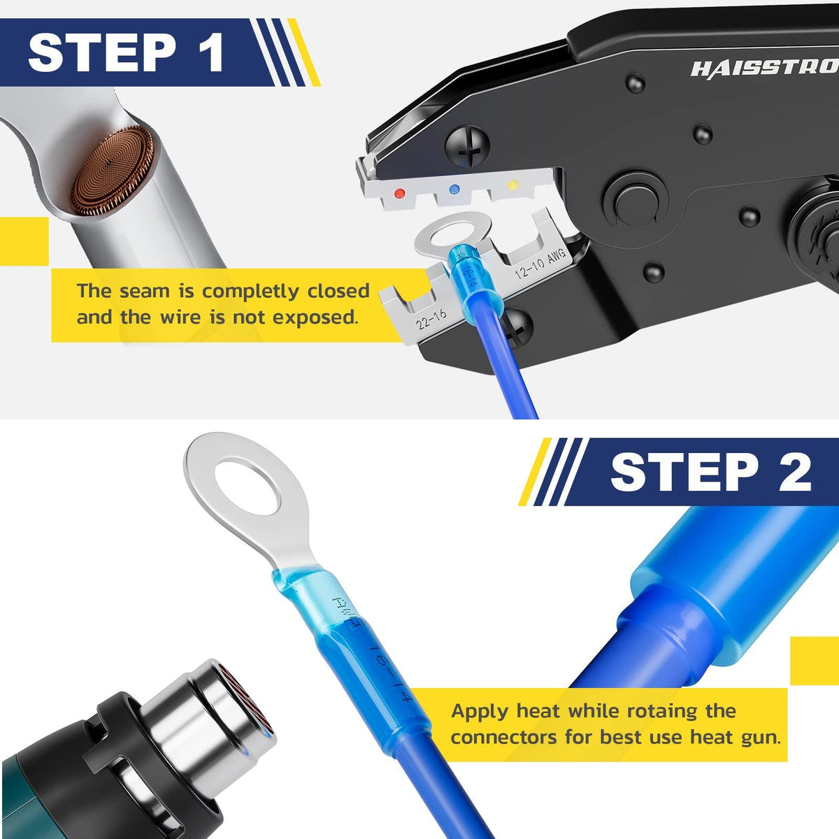
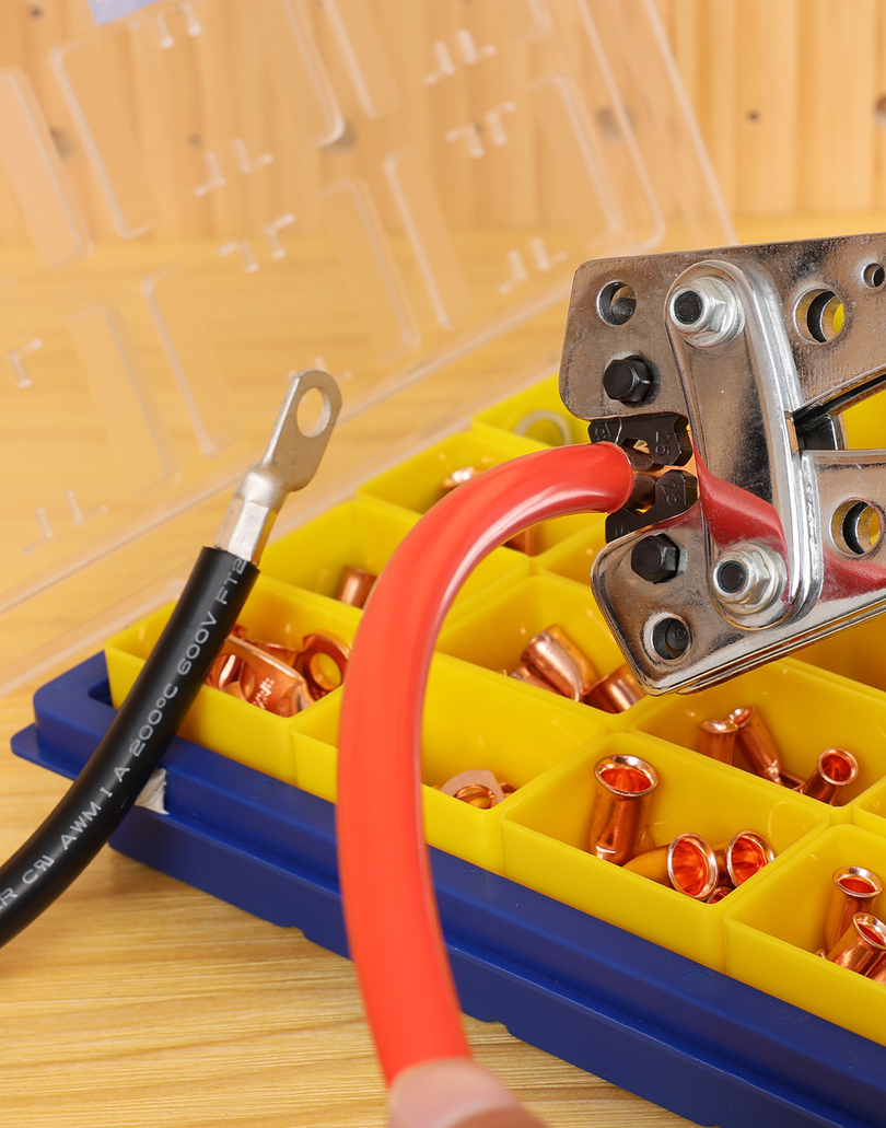
- Complete the full ratchet cycle and inspect barrel position, conductor capture and insulation clearance.
- Perform the required pull test and electrical resistance check before thermal testing.
Important: A mechanically good crimp is not automatically a high-temperature connection. Material ratings and installation quality must both pass.
Use heat shrink only when its own rating passes
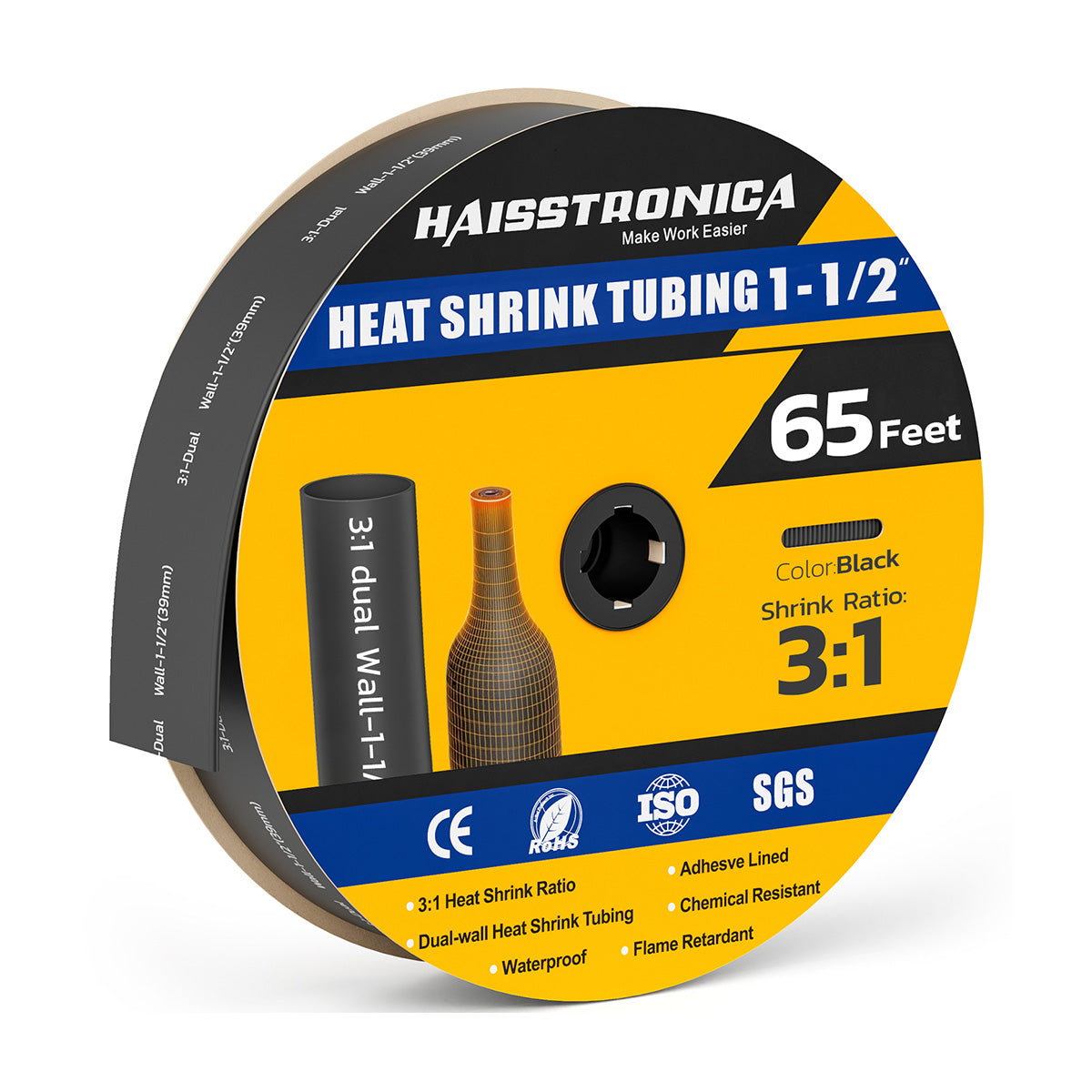
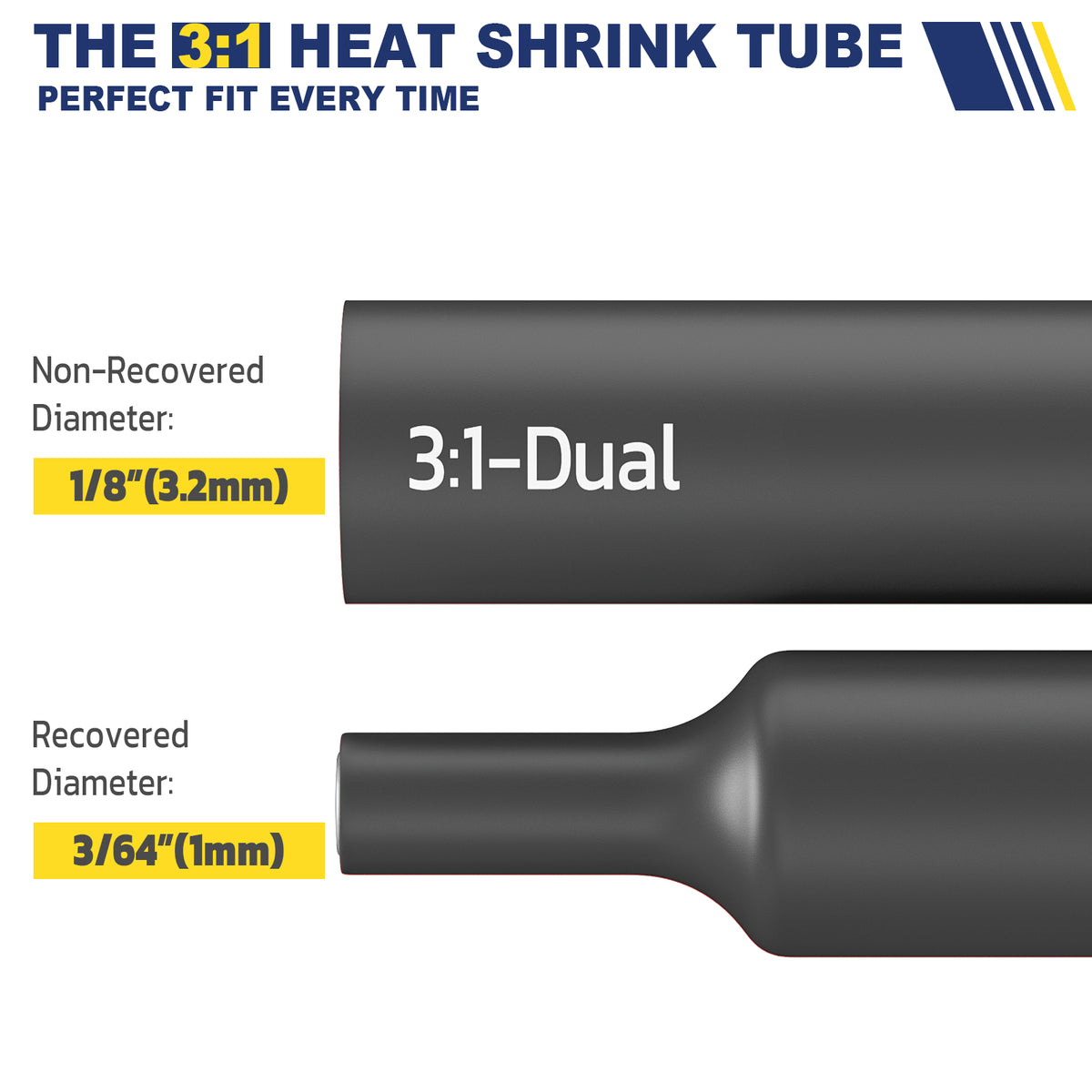
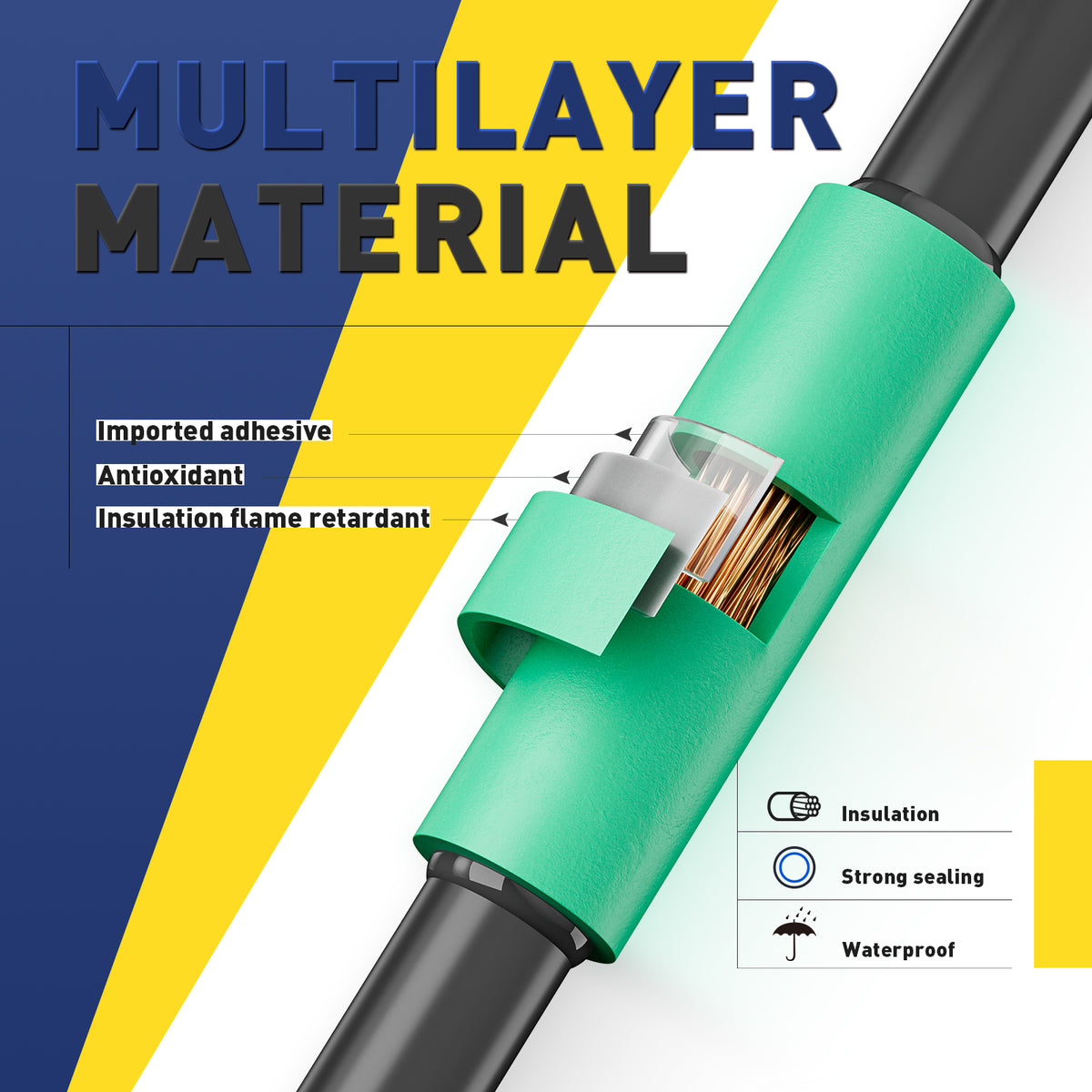
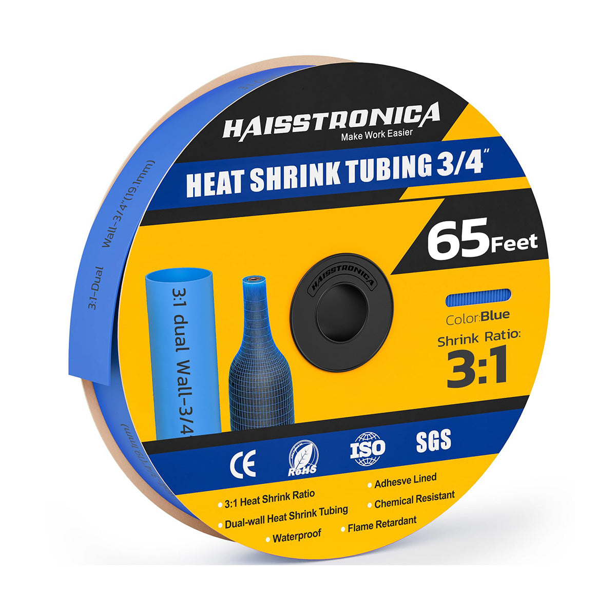
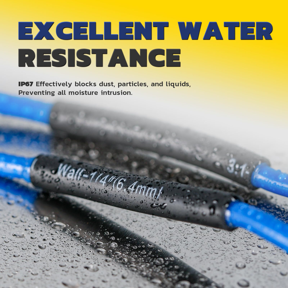
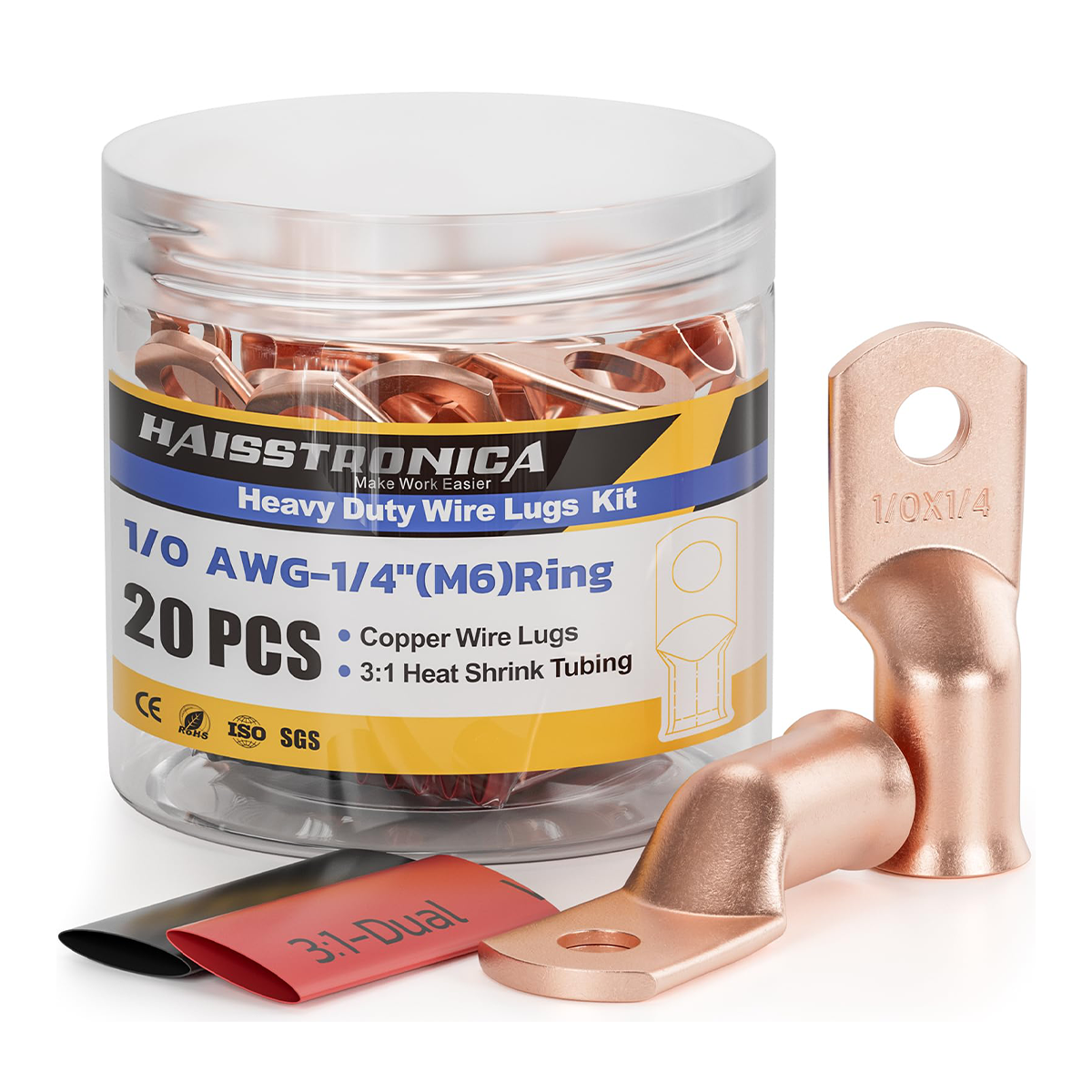
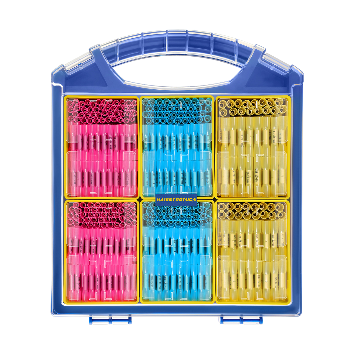
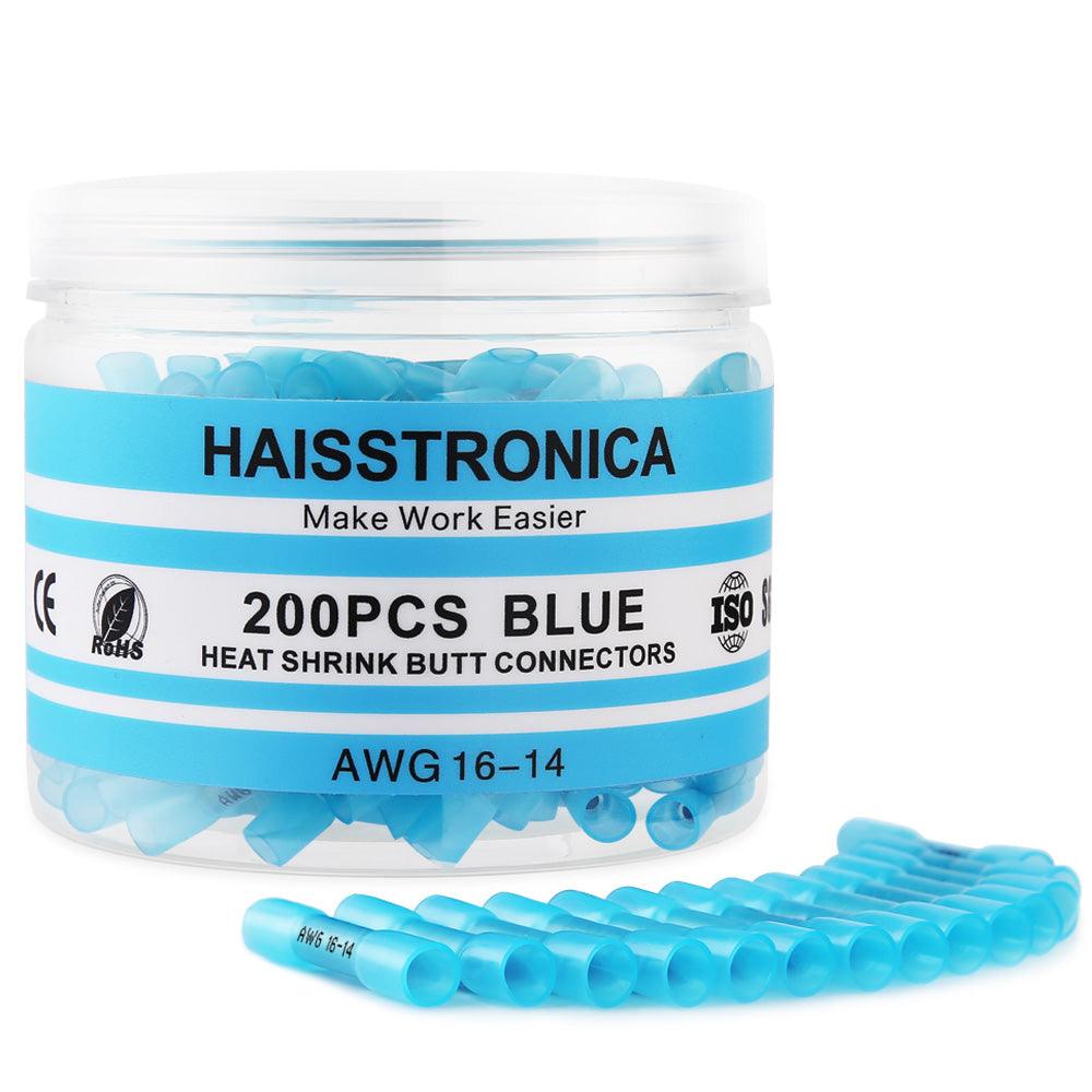
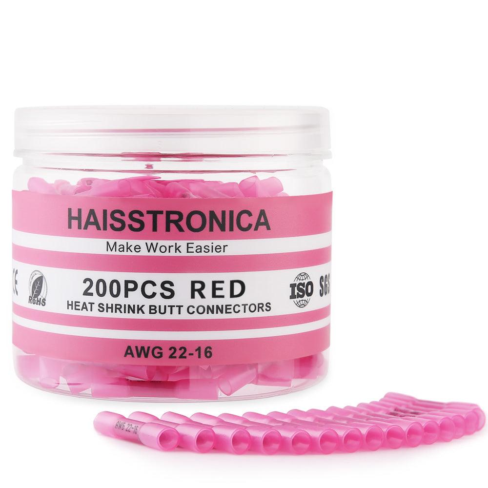
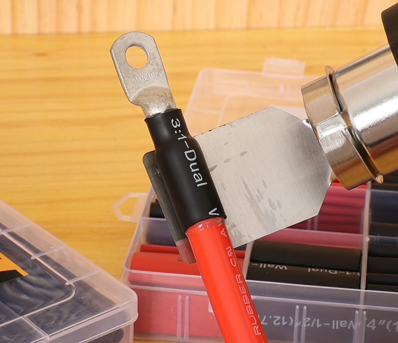
Heat shrink can add insulation, strain relief and sealing, but it does not increase the terminal’s temperature rating. Verify the tubing, adhesive, recovered diameter and continuous-use temperature for the exact product before selection.
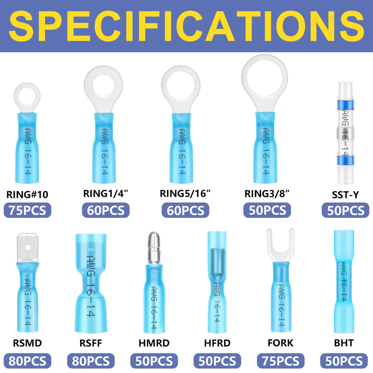
Review tubing + verify datasheet →
Commission and monitor the finished connection
Record resistance and temperature after installation.
Operate at expected maximum load and duty cycle.
Investigate any repeatable rise versus the baseline.
Frequently asked questions
Can I use a standard connector if the exposure is brief?
Only if the manufacturer publishes a short-term or peak rating that covers the actual temperature, duration and number of cycles. Do not infer this from a continuous rating.
Does removing the plastic insulation make any terminal suitable for 150°C?
No. The terminal material, plating, conductor, current, vibration, enclosure and any added insulation still require documented compatibility.
Can heat shrink make a connector high-temperature?
No. Tubing protects only within its own rating and cannot raise the rating of the underlying connection.
Buy only after every rating matches
For 150°C+ service—or whenever a datasheet is incomplete—stop the purchase path and specify a documented industrial high-temperature system.