
When planning to buy a kit of heat shrink solder seal wire connectors, one size does not fit all. These connectors come in multiple gauge ranges (typically covering wires from about 26 AWG up to 10 AWG) and each size is color-coded. But which sizes will you actually need the most? In this guide, we’ll break down how to choose the right gauge mix before you purchase a kit. We’ll consider different usage scenarios (automotive wiring, marine applications, electronics, etc.), discuss the connector form factors and why they matter, and answer frequently asked questions about using these solder and seal connectors. By the end, you’ll know exactly what to look for in a wire connectors kit so you get the best value and have the right connector on hand for every job.
👉 Achieve lab-clean joins with Haisstronica heat shrink soldering sleeves.

Scenario Mix: Matching Connector Sizes to Your Wiring Needs
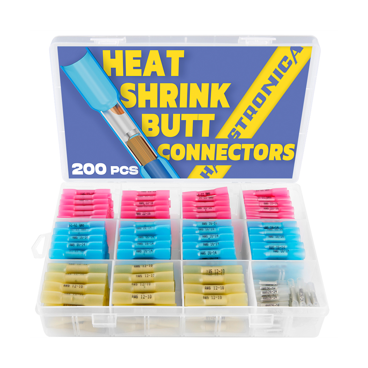
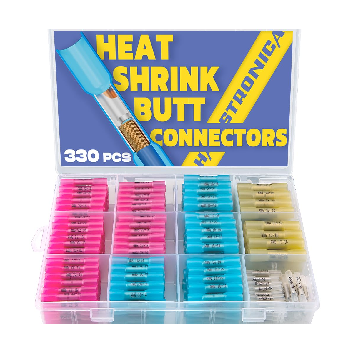
Not all projects use the same wire sizes, so it’s important to plan your kit around the scenarios you encounter most. Solder seal connectors (often called heat shrink solder connectors, solder splices, or solder shrink connectors) typically come in four primary sizes for different wire gauge ranges:
-
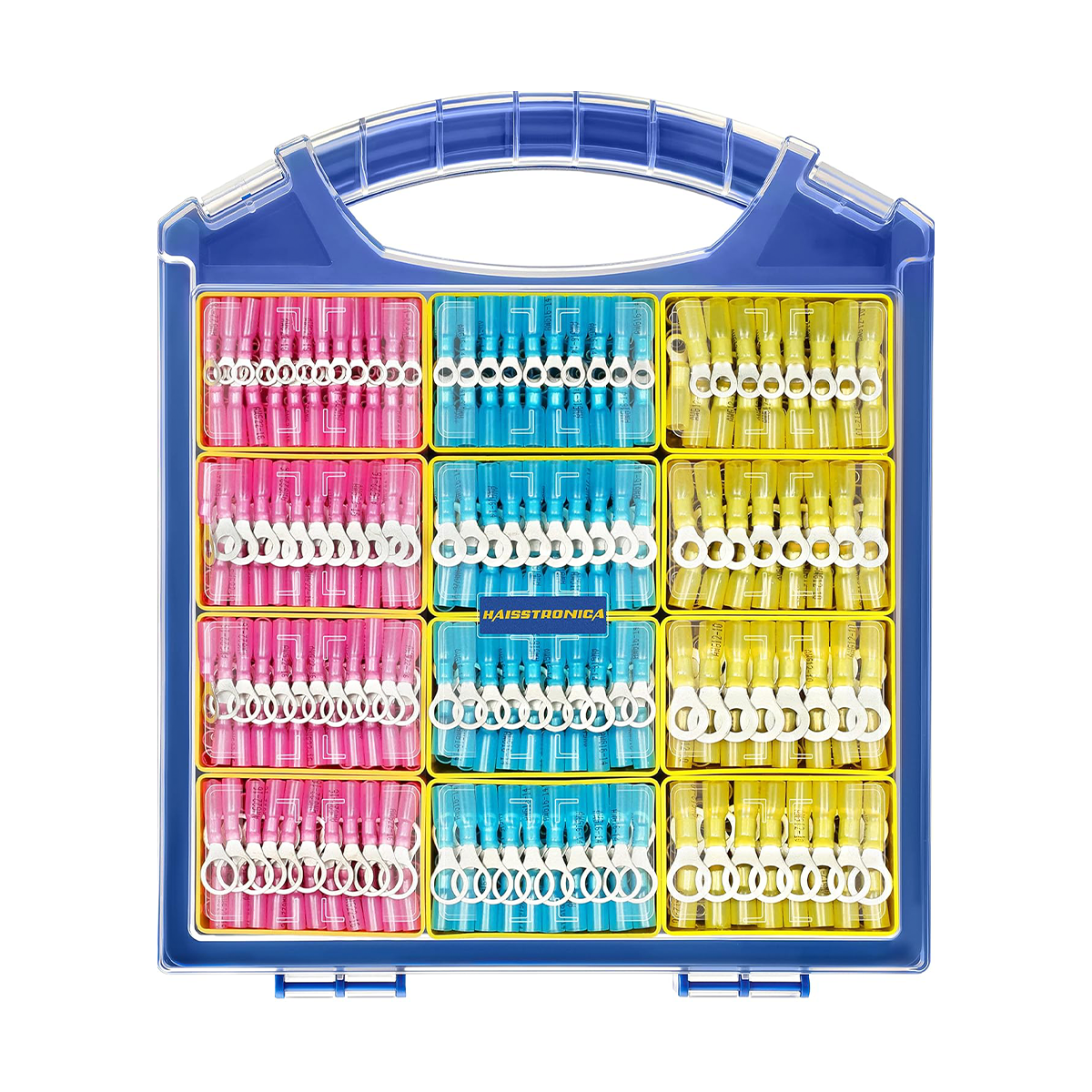
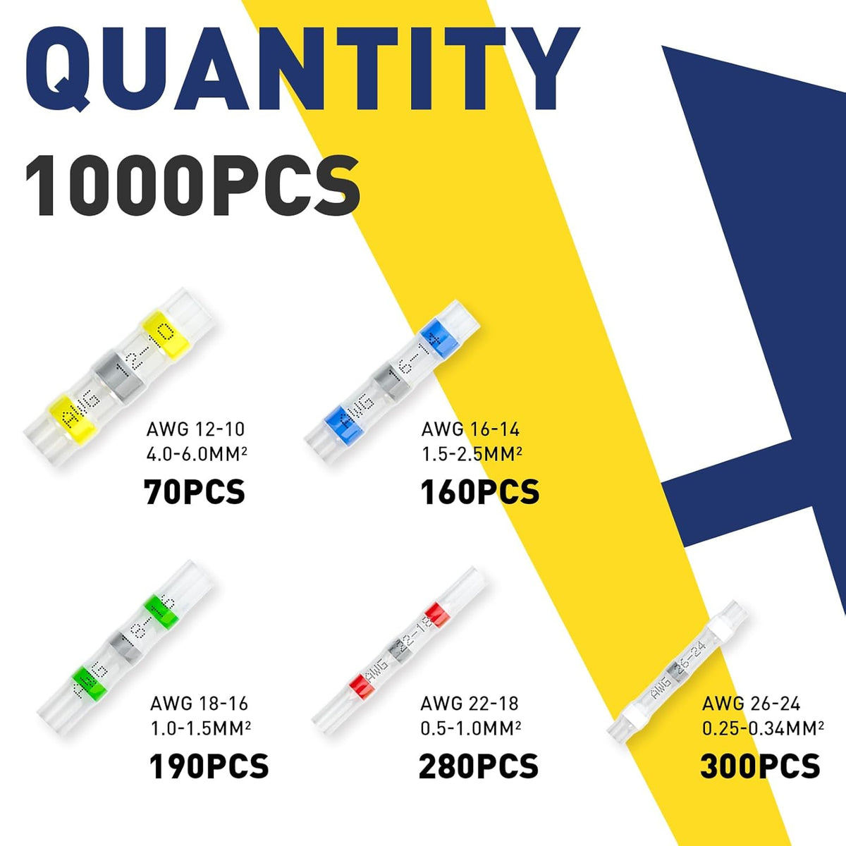
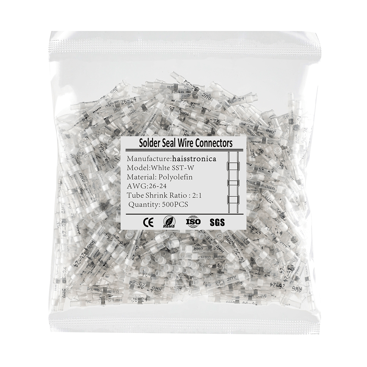
White (Smallest) – For ~26–24 AWG wires (around 0.14–0.25 mm²).
-
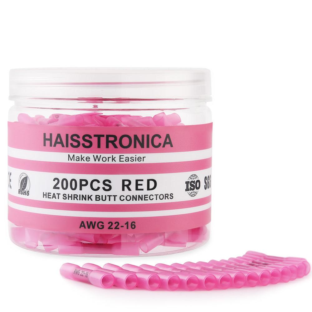
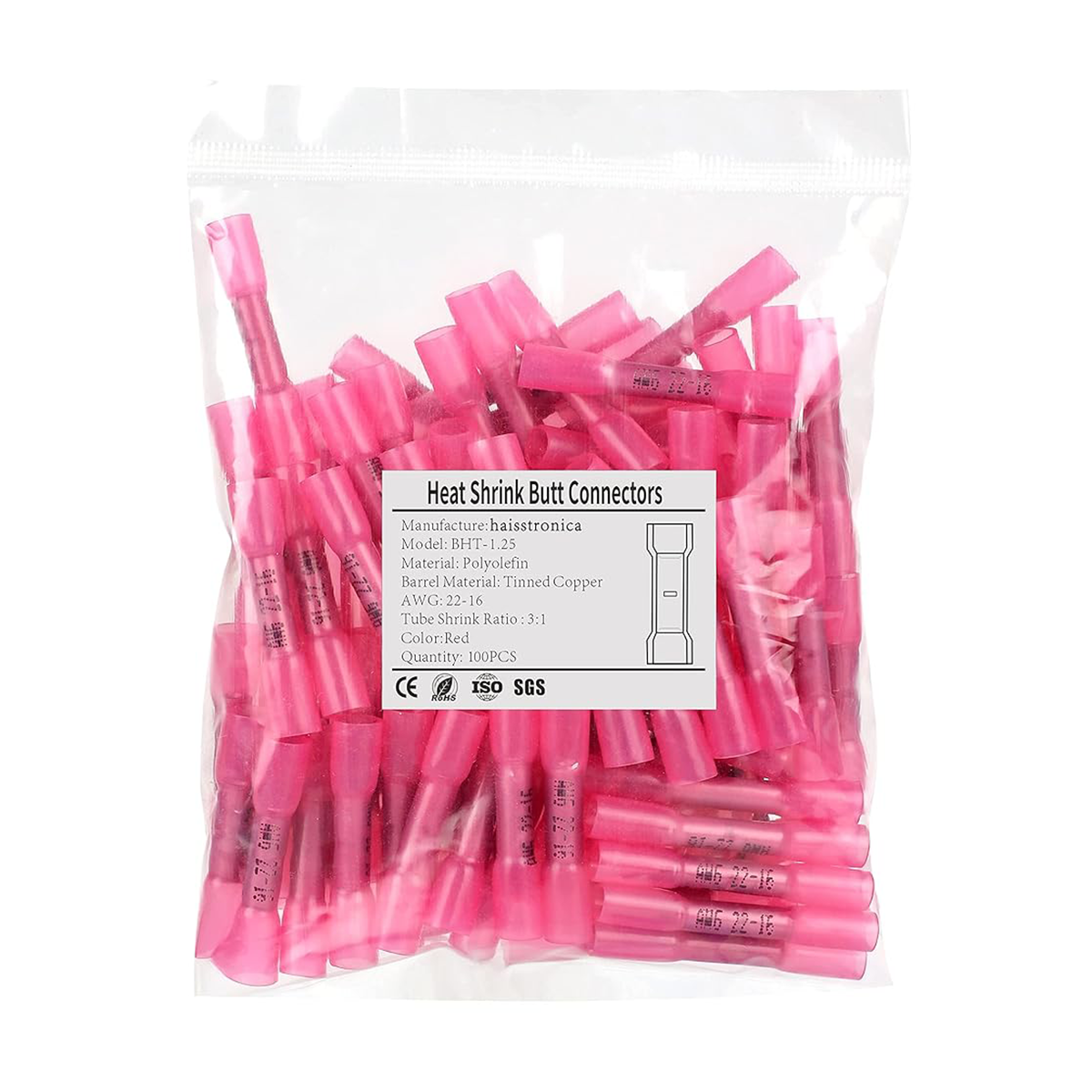
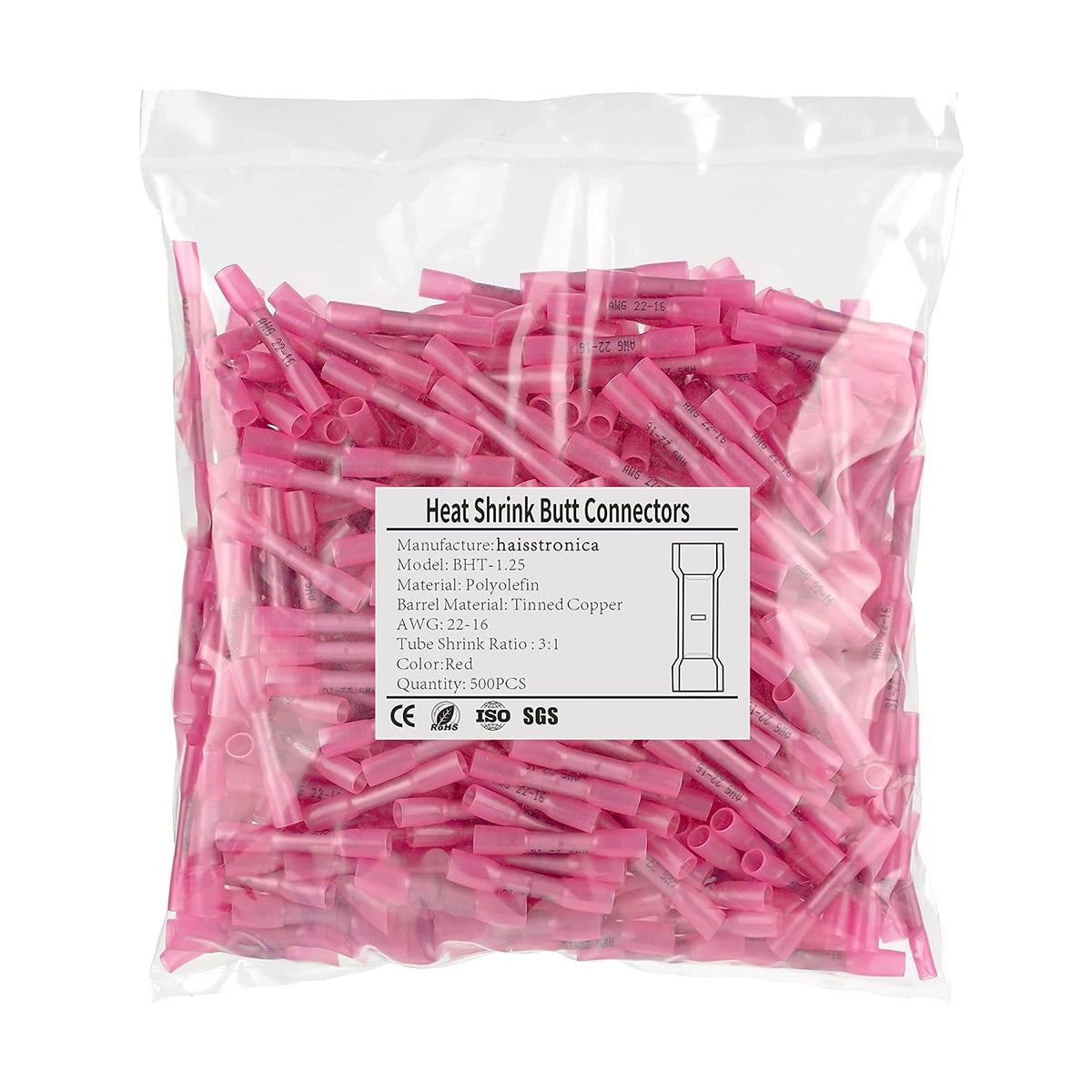
Red (Small) – For ~22–18 AWG wires (0.34–0.75 mm²).
-
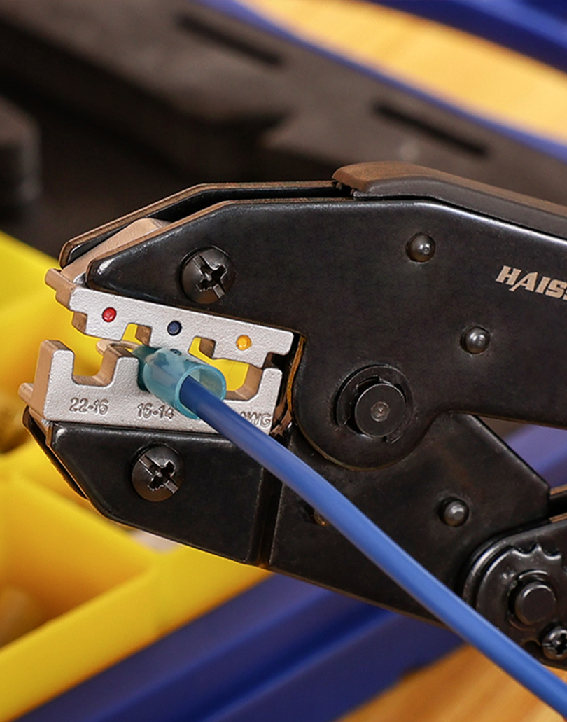
Blue (Medium) – For ~16–14 AWG wires (1.5–2.5 mm²).
-
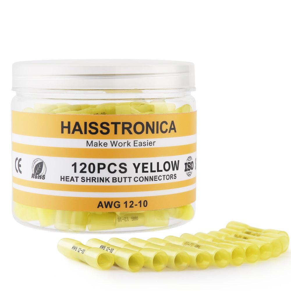
Yellow (Large) – For ~12–10 AWG wires (4–6 mm²).
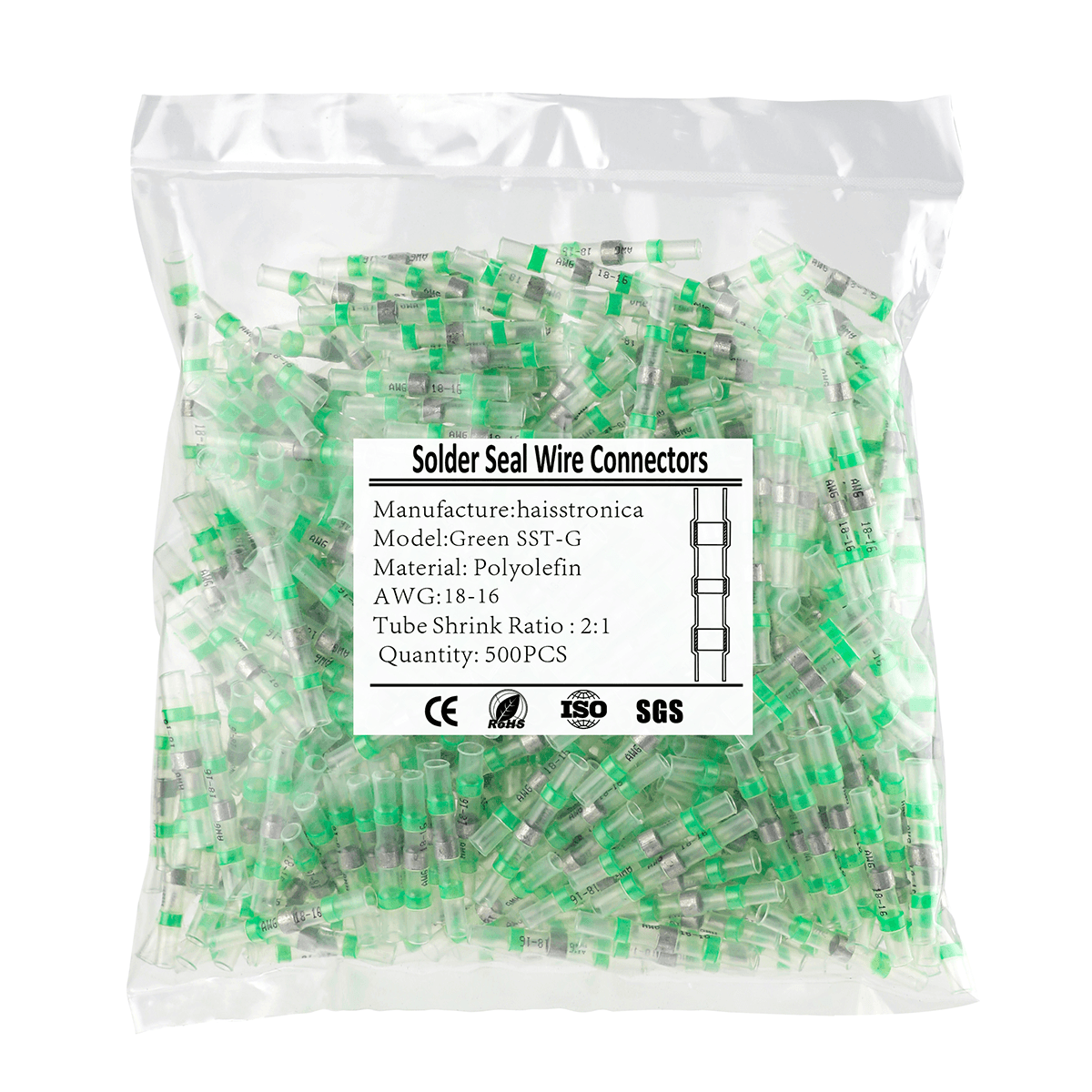
(Some kits include an extra intermediate size, e.g. a Green sleeve for ~18–16 AWG, but many standard kits use the four main colors above, covering the same range with slight overlap.)
Your goal is to estimate which of these connector sizes you’ll use most frequently, based on the typical wire gauges in your work. Let’s look at a few common scenarios:
-
Automotive Wiring (12V DC systems): Most factory automotive primary wire is around 18 AWG for general circuits, with heavier accessories using 14 or 12 AWG, and smaller sensor or audio wires at 20–22 AWG. For example, 18 AWG is common for dash wires and lighting (signals, low-current), 16–14 AWG for headlights or power feeds, and 12 AWG for certain pumps or tow wiring. This means red and blue solder connectors (covering 22–18 and 16–14 AWG) will likely see the most use in a car or truck setting. You should ensure your kit has plenty of these mid-range sizes. Yellow connectors (12–10 AWG) are used more sparingly – perhaps for hooking up an amplifier or a trailer brake controller feed – so a smaller quantity suffices. White connectors (26–24 AWG) might only be needed if you’re working on very small wires (like LED indicator lights, some sensor harnesses, or aftermarket electronics). In general, for automotive use, plan on a heavy emphasis on blue and red solder seal connectors, a handful of yellows for the occasional heavy gauge splice, and a few whites for tiny leads.
-
Trailer & RV Wiring: Trailers and RVs also use similar wire sizes: often 16–18 AWG for marker lights, brakes, interior lights, etc., and occasionally 12–14 AWG for charging circuits or higher loads. A mix weighted toward red (22–18 AWG) and blue (16–14 AWG) sleeves works well here. Trailer light harness repairs, for instance, are commonly done with butt splice solder connectors in the 18–14 AWG range. As one guide notes, quick solder-seal splices shine for things like lighting and accessory circuits on trailers, where they shorten repair time compared to strip-crimp-heat methods. You’ll still want a few yellows if dealing with an RV battery connection or trailer brake controller lead (often 10–12 AWG), but those larger wires might be better served with crimp lugs if very high current (more on that later).
-
Marine Wiring: Boats typically run 16 or 14 AWG for many circuits (e.g. lights, pumps) as a minimum standard (in fact, marine standards often require at least 16 AWG for anything carrying significant current). So blue connectors (16–14 AWG) are vital in a marine kit. 18 AWG (red sleeve) might appear for some small electronics or lighting, but many marine installers upsize to 16 AWG for added robustness. Heavier marine appliances (bilge pumps, windlasses) use 10–12 AWG, where you might use a few yellow solder sleeves only if the connection is in a protected location – otherwise, marine practice leans toward crimped, sealed terminals for anything critical. White (26–24 AWG) connectors will be rarely used on a boat, since such thin wires are uncommon except in delicate electronics (which might be better soldered and sealed manually or use specialized connectors). Therefore, a marine-focused kit might skew heavily to blue and red, include some yellow, and possibly very few white. Keep in mind that marine standards (ABYC) advise that “solder shall not be the sole means of mechanical connection in any circuit” – meaning any soldered joint on a boat should also be physically supported or crimped, to prevent vibration from breaking the wire. In practice, this means using solder seal connectors only in low-vibration areas and always securing the wires on both sides of the splice.
-
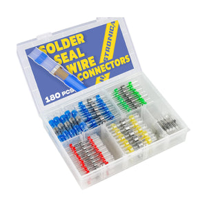
Home DIY and Electronics: For bench projects, Arduino/Raspberry Pi wiring, drones/RC, or instrument wiring, the wires are often small gauge (20–28 AWG). Here, the white connectors (26–24 AWG) and red connectors (22–18 AWG) dominate. It’s common to splice fine wires for sensors, LED strips, etc. using these solder sleeves, because they offer a quick way to join tiny strands while also adding a bit of strain relief. Blue (16–14) might still come in handy if you’re hooking into a thicker lead or a power supply cable, but you may use very few yellows (unless working with automotive-style fuse blocks or larger DC supply lines in a DIY project). If your focus is electronics, you might even consider a smaller kit geared toward the lower AWG (higher gauge number) range or ensure the kit you buy has a generous share of whites and reds. For instance, one 180-piece kit from Haisstronica allocates about 45 white, 60 red connectors, and fewer of the large sizes, reflecting that in many general-purpose kits the mid-small sizes are most numerous.
-
Industrial/Machine Wiring: Often uses a mix: small control wires (18–22 AWG) and power wires (12–14 AWG). If you plan to use solder seal connectors for machinery or vehicles, again prioritize red and blue, but also double-check if solder splices are appropriate per any codes or manufacturer guidelines (some industries prefer crimp terminals or screw terminals for serviceability). For field repairs, however, a solder seal butt splice can be a lifesaver when you don’t have a crimp tool on hand – just ensure the environment isn’t one with constant flex or high temps.
Bottom line: plan your kit mix based on wire gauge usage. In most cases, 22–18 AWG and 16–14 AWG connectors are consumed fastest, so buy a kit that has plenty of red and blue pieces. A decent number of white (26–24 AWG) and a smaller number of yellow (12–10 AWG) connectors usually suffices for occasional thin or heavy wires. If a pre-packaged kit’s proportions don’t match your needs, consider getting extra packs of the specific size you need (e.g. a bag of additional yellow solder seal connectors for a project with many 12 AWG splices, or extra white ones for fine wires). The good news: many kits list exactly how many of each color are included – for example, an automotive-focused 180pcs kit might include Yellow 15 pcs, Blue 60 pcs, Red 60 pcs, White 45 pcs, whereas a more electronics-focused kit might shift those counts differently. Checking those details helps you pick the right product.
Lastly, remember that wire gauge ranges overlap between connector sizes. If you’re on the cusp (say you have a lot of 18 AWG wires), you might be able to use either a red or blue connector. But generally choose the smaller size that still covers the gauge – a snug fit ensures the solder ring properly melts around all strands and the heat shrink tubing fully seals the insulation. Using an over-sized sleeve “just in case” can lead to weak mechanical strength or water ingress (the tubing might not shrink tight enough on the insulation if under-filled). As one manufacturer points out, mismatched sizing is a top cause of pull-outs and “no seal” failures with solder sleeves. So, aim to use the correct connector for the gauge, and stock your kit accordingly.
👉 Depend on Haisstronica heat shrink with solder for harsh environments.

Form Factors of Solder & Heat Shrink Connectors
In this context, “form factor” refers to the design and types of connectors we’re dealing with. Solder-seal connectors are essentially butt splice connectors that incorporate a low-melt solder ring and heat-activated adhesive inside a heat shrink tube. They are a one-step solution for joining two wires end-to-end (or end-to-middle if repairing a break). Here we’ll explore the key form factor characteristics and compare them to other connector styles:
-
One Design, Multiple Sizes: All solder seal connectors have a similar shape – a cylindrical transparent tube with a band of solder in the middle (usually pre-fluxed solder alloy) and rings of colored adhesive near each end. The different AWG ranges (colors) are essentially the same design scaled in diameter and length. For example, a yellow 12–10 AWG connector is physically larger (wider tube, more solder) than a red 22–18 AWG connector. The form factor scaling matters in use: larger connectors require more heat to fully melt the solder and shrink the tubing, and they accommodate thicker insulation diameters. Meanwhile, the smallest connectors (white 26–24 AWG) are tiny and need careful heating to avoid burning the tube. Despite size differences, the heat shrink ratio is often 3:1 or 4:1 across these connectors, meaning they can shrink to about one-third or one-quarter of their original diameter to tightly seal on the wire insulation. A good kit will use high-quality polyolefin tubing that is crystal-clear (for inspection) and dual-wall (with adhesive) for water resistance. Form-factor wise, you’re getting a sealed solder sleeve – sometimes also called a solder sleeve splice – intended for in-line splicing of wires.
-
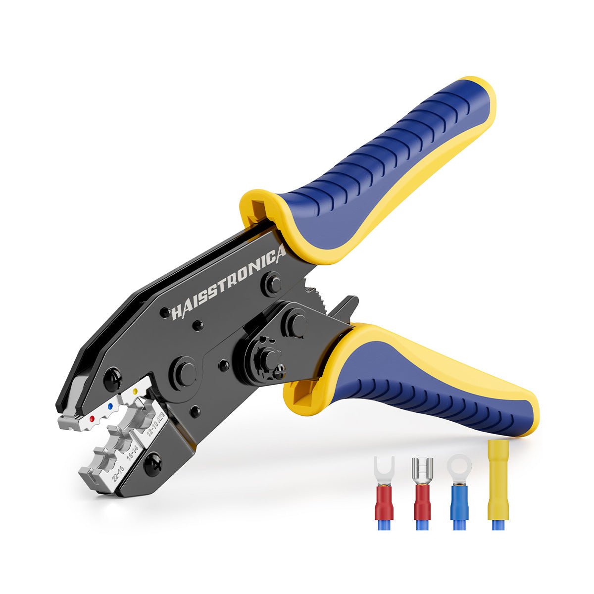
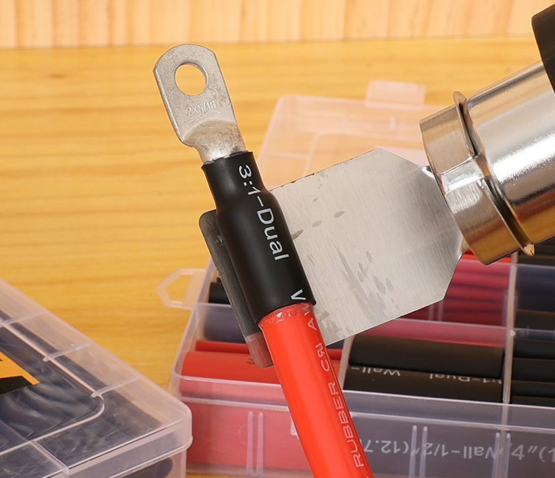
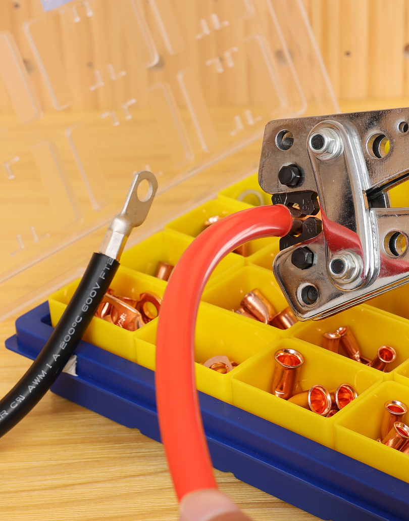
Wire Connector vs. Terminal: It’s important to note that solder seal wire connectors in kits are almost always butt splice style. They are not ring terminals, spade terminals, or bullet connectors. Those other types (ring, spade, etc.) typically require crimping onto the wire and cannot have a pre-loaded solder ring because of their shape (you wouldn’t slide a ring terminal over a wire like a tube; instead you insert wire into a metal barrel). So the form factor limitation is that solder seal connectors are for joining wires together, not for terminating a wire to a bolt or plug. If your project involves connecting wires to a battery, fuse block, or component with studs/blades, you’ll still need traditional crimp-and-seal connectors (e.g. heat shrink ring terminals, spade connectors) or solder the wire to the terminal manually. In summary: use solder seal butt connectors for splicing wire-to-wire; use appropriate terminals for wire-to-device connections. Both can be part of your toolkit – for instance, you might crimp a ring terminal on the end of a cable and use a solder seal butt splice somewhere in the middle of the run for a repair.
-
Solder vs Crimp Form Factor: A solder seal connector could be seen as a hybrid form factor – it provides an electrical soldered joint like a traditional soldering job, but also provides a sealed insulation like a crimp connector with heat shrink. However, it does not involve any crimping action. There is no metal ferrule or barrel to crush with pliers; the mechanical strength comes from the solder bond plus the shrink tube gripping the insulation and the adhesive anchoring it. Because of this, sometimes these products are marketed as solderless connectors in the sense that you don’t need a soldering iron (the solder melts with a heat gun) – but be careful, “solderless” in electronics usually refers to methods that use no solder at all (like crimp or push-in connectors). Here, solder is used, just without a separate soldering process by the user. On the flip side, truly solderless wire connectors (like insulated crimp butt connectors, Wago™ lever nuts, or screw terminals) have a completely different form factor and use mechanical force to secure the wire. Each approach has its merits: solder-seal splices give a clean look and a solid bond but create a stiff joint; crimp connectors can be more flexible if done right. In some cases, people even use a combination – e.g. a crimped connection followed by solder (“crimp and solder connectors”) – though this is usually not necessary if each method is properly executed, and crimping vs soldering is a topic we address in the FAQ. The key takeaway for form factor is: don’t try to crimp a solder seal connector – it’s not designed for that. If you squeeze it with pliers, you’ll likely crack the solder preform or the tubing. Instead, the proper installation is to insert wires and apply heat, allowing the solder to flow and the tube to shrink. This simplicity is why some call them “self-soldering connectors” or “solder stick connectors” – you just add heat and they do the rest.
-
Heat Source and Technique: All solder seal connectors, regardless of size, require a heat tool to activate. A heat gun with a concentrator nozzle is the preferred tool to evenly heat the solder ring and then the tubing. In terms of form factor usage, you typically heat the middle first (to melt the solder) then the ends (to shrink and seal the tubing). This is a one-shot operation; once the solder solidifies, you can’t reflow it without reheating the whole joint (which risks damaging the wire insulation). So plan carefully: ensure wires have about 6mm (~1/4”) of stripped copper overlapping under the solder ring before heating. Unlike soldering with an iron, you can’t “add more solder” to these pre-filled connectors – the amount in the ring is fixed and (if it’s a quality product) calibrated for the connector size. The form factor is optimized when used as intended: insert, heat, cool, done. If you find yourself wanting to stick a soldering iron in there or add solder, it might mean the connector was too large for the wire (solder didn’t properly flow into the strands) or was overheated/underheated. A well-designed connector will have enough solder to wrap the joint and enough adhesive to form visible seal rings at the edges.
-
Visual Inspection: The clear tubing form factor is a huge advantage. Traditional crimped butt connectors are opaque, so you rely on pull tests to know if the crimp took, and you can’t easily see if the wire is fully inserted. With these solder sleeves, the entire process is visible: you can see the stripped wire overlap before heating, watch the solder ring melt and wick into the strands, and observe the adhesive melting out to the edges. This transparency is by design – as one industry guide notes, “Clear bodies = visual confirmation of overlap, solder flow, and seal.” Cheap knock-offs sometimes use more opaque nylon that can hide whether the solder fully melted, so for quality, crystal-clear polyolefin tubing is the gold standard. The form factor should facilitate inspection; it’s part of what separates good connectors from subpar ones.
-
Physical Constraints: Because these connectors rely on heat, there are some form-factor related constraints. You need access to both sides of the splice with a heat tool, which can be challenging in very tight harnesses or near plastic components that could melt. A connector’s length is also a consideration: a solder-seal butt splice is usually a bit longer than a comparable crimp butt splice barrel, because it has to accommodate the solder ring and adhesive space. If your wire has very limited slack, ensure you can accommodate about ~1 inch (2–3 cm) of length for the splice. Also, multiple solder splices in close proximity should be staggered in a harness, so they don’t all lump in one spot (same as you would with crimp splices). These planning considerations tie back into kit mix as well – for instance, if you’re working on a tight motorcycle harness with mostly 20–16 AWG wires, you might lean on the smaller red connectors to keep splice length minimal, rather than using a blue connector on a 16 AWG if not necessary (red covers 18 AWG max, but some brands’ red will also just about handle 16 AWG if it’s on the cusp and insulation diameter fits). Always follow the printed gauge range though – if a connector is labeled 22–18 AWG and you attempt to use it on 16 AWG, you risk not enough solder or difficulty inserting the wire. Manufacturers match the solder quantity to the intended wire cross-section for a reason.
-
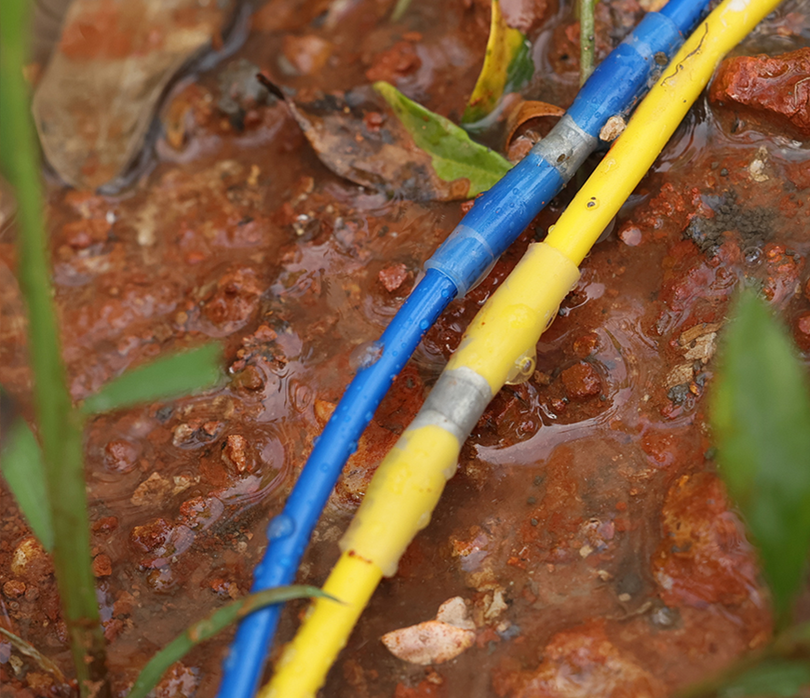
Environmental Sealing: One major form factor advantage of these connectors is the sealing capability. They are often advertised as waterproof solder connectors or sealed solder connectors, which is true to an extent: the dual-wall tubing has a meltable adhesive liner that, when heated, forms a water-resistant seal around the wire insulation. When properly heated, you’ll see a bit of adhesive ooze out at each end, like a bead, which indicates a good seal. This effectively encapsulates the soldered joint, protecting it from moisture and corrosion. In contrast, a hand-soldered joint with just regular heat shrink (no adhesive) isn’t truly sealed – moisture can wick in along the wire strands. Similarly, a bare crimp butt splice (non-sealed) can corrode if exposed. The marine-grade versions of these solder connectors use adhesive-lined heat shrink specifically to address that, making them water-resistant once cooled. Note the terminology: waterproof in marketing doesn’t mean you can splice wires underwater or that it’s IP68 rated for permanent submersion. It means the splice will resist water ingress from splashes, rain, maybe short-term submersion, especially if the wire itself is marine grade (tinned copper). For critical watertight needs, additional steps (like enclosing the splice in a junction box or using silicone tape over it) might be wise. Nonetheless, properly heated solder-seal splices are proven to block out moisture and even salt spray, which is why they’re popular in boat trailers and off-road vehicle wiring where exposure is frequent. The adhesive in these connectors essentially acts as a wire sealant, keeping corrosion at bay on the conductors.
In summary, the solder-seal connector’s form factor is a butt splice with a built-in solder & heat-shrink system. It’s a compact, efficient solution for wire-to-wire joins. However, it’s not a one-size-fits-all for every connection type. Recognize when you need a different connector form (ring, fork, plug, etc.), and don’t try to force the solder sleeve to do jobs it wasn’t meant for (like terminating to a battery post – use a proper lug). When used in the right context, the form factor offers three functions in one piece: crimp-like mechanical hold, soldered electrical continuity, and sealed insulation. This triple-action design is what makes them appealing in many professional kits and why many automotive wire connector kits include them for quick repairs.
👉 Seal and protect with Haisstronica heat shrink solder solutions.

FAQ: Using Solder Seal Wire Connectors
In this section, we address common questions and concerns about solder and heat shrink connectors and their usage. Professionals and hobbyists alike often debate the merits of these connectors and want to know the do’s and don’ts. Here are the key FAQs:
Q1. Are solder seal connectors as reliable as crimp connectors?
A: It depends on the application. Solder-seal connectors create a solid electrical connection with low resistance, and the heat shrink provides strain relief and sealing. In a static environment (no movement, no vibration), a properly made solder joint can be very reliable and slightly lower in resistance than a crimp. However, in high-vibration or flexing environments (e.g. on vehicles, machinery), a soldered joint is more prone to fatigue cracking. The solder wicks into the wire strands, effectively turning a flexible multi-strand wire into a solid core over the length of the joint. This can cause the wire to break just at the end of the solder, if the wire is repetitively flexed. Crimped connections, by contrast, preserve more of the wire’s flexibility and can better absorb vibration if done correctly. In fact, multiple industry standards and experts note that “crimped connections are more flexible, heat-resistant, and vibration-resistant than soldered ones”. For example, the American Boat & Yacht Council (ABYC) explicitly warns against solder-only connections on boats, requiring that if solder is used, the connection must be supported so it doesn’t flex. In automotive contexts, many OEMs prefer crimps for the same reason – but that doesn’t mean solder seal connectors have no place. Use them in spots that are relatively stationary or well-supported (wire harness secured on both sides of the splice). Avoid them for wires that constantly move or vibrate (engine bay connections, door hinge wires, etc.) – a quality crimp or a crimp & seal butt connector might be better there. In short, solder seal connectors are reliable when properly sized and installed in the right environment. They are not inferior by default; they simply have different strengths. Many professional installers carry both types and choose case-by-case – for instance, using solder seal splices for adding a new light into an existing harness (fast and sealed), but using crimped terminals for a starter cable repair (high current and vibration).
Q2. How waterproof are these connectors? Can they be used outdoors or underwater?
A: Solder seal connectors are designed to be water-resistant to a high degree. The combination of melted adhesive lining and snug shrink tubing forms a seal that will keep out water, dust, and chemicals in most situations. They are often marketed as waterproof wire connectors, and in practical terms they will hold up to rain, engine bay splashes, marine splash, and even brief shallow submersion (for example, trailer light wiring that gets dunked when launching a boat). The key is proper heating: you should see adhesive “squeeze-out” at the ends, indicating the gaps are filled with melted glue. If you don’t see that, the connection might not be fully sealed. While these connectors don’t carry an official IP rating, field experience and tests by manufacturers show that a correctly installed solder-seal butt splice can be very robust against the elements. However, for underwater use or continuous submersion, additional protection is advised. Prolonged submersion can, over time, find a path through any microscopic gaps. If you need an underwater splice (for say, a submersible pump wire), you might use these connectors and then over-mold with an epoxy, or use specialty underwater splice kits. In summary: outdoors in the rain or marine environment – yes, these are suitable and far better than unsealed splices. Underground or underwater permanently – use caution and consider added sealing measures. Also remember that waterproof does not equal strain-proof: secure the wires so that tension isn’t constantly pulling on the sealed joint, or water could eventually work in from stress or capillary action along the strands.
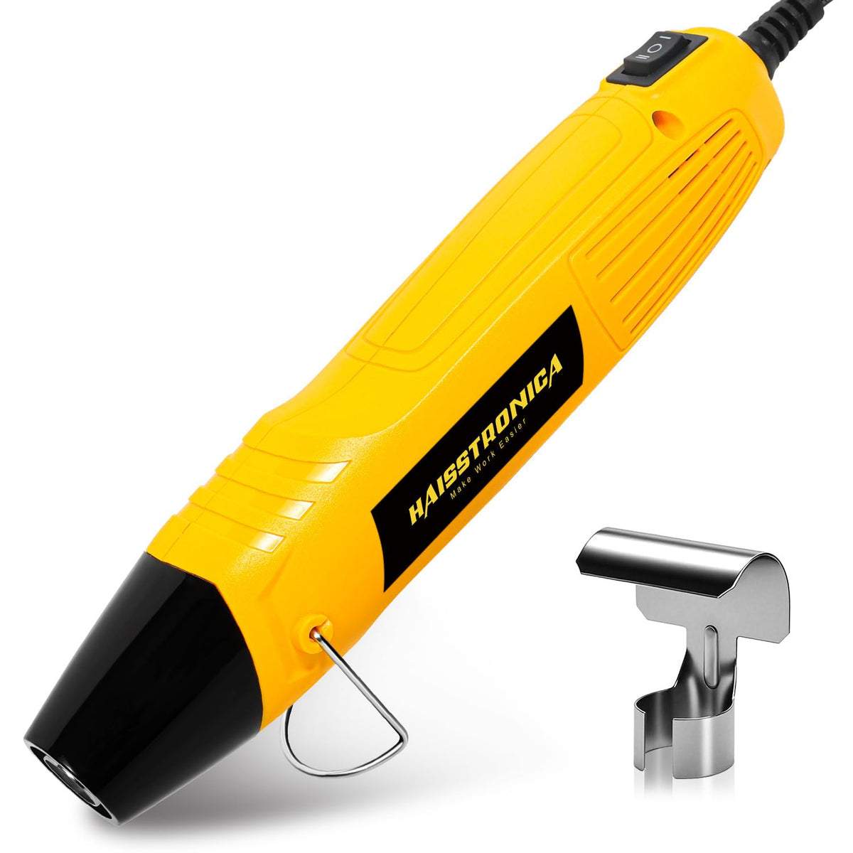
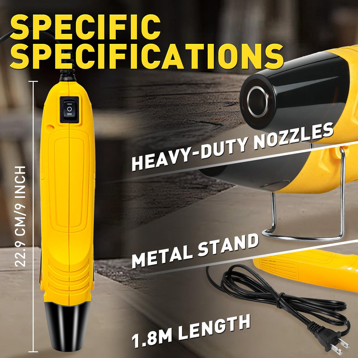
Q3. What’s the proper way to heat these connectors? Can I use a lighter or soldering iron?
A: The best tool is a heat gun (hot air gun) around 600–700°F (315–370°C) with a focused nozzle. This provides even, controlled heat. The general technique, as mentioned earlier, is to heat the solder ring first until it visibly melts and flows, then move heat to the tubing ends to shrink and melt the adhesive. Using a soldering iron is not recommended – these connectors are meant to be soldered by the internal ring melting from ambient heat. An iron would only heat one side and likely just make a mess (the solder ring is inside the tubing). What about using a common lighter or torch? In a pinch, some users do use a butane lighter or micro-torch, and it can work, but it’s easy to overheat and scorch the tubing or not heat evenly. A windproof butane lighter can get hot enough to melt the solder, but you must keep it moving to avoid burning the plastic. In fact, one frequently asked question is exactly this, and the consensus is that while a lighter can work, it’s better to carry a small 12V heat gun or even a heat tool that can run off a butane canister for field work. The cost of a proper heat gun is small compared to the potential of ruining multiple connectors with an open flame. If you absolutely must use a lighter, use the soft part of the flame (not the inner blue cone) and wave it back and forth under the solder ring and then the ends. Watch the solder – once it collapses and you see shiny flow, remove heat to avoid boiling the solder or burning insulation. And ensure no fuel residue gets on the connection (some lighters can leave soot). Bottom line: a heat gun is the right tool; a lighter is a last resort. Do not use a regular soldering iron on these; it’s the wrong approach.
Q4. Can I connect different gauge wires with one solder seal connector?
A: Yes, within reason. A common scenario is splicing a thinner wire to a thicker wire (for example, adding a small gauge lead onto a heavier gauge main wire). The connectors have some ability to accommodate this, but you must choose the connector size based on the larger wire’s gauge for solder capacity, and then ensure the tubing can still shrink onto the smaller wire’s insulation. For instance, say you need to join a 16 AWG to a 22 AWG wire – a blue connector (16–14 AWG) covers the larger 16 AWG. It will have enough solder for the 16 AWG side, but the 22 AWG side is much smaller than the blue tube’s minimum. One trick is to strip extra length on the thin wire, fold it over once or twice to effectively increase its cross-section, or even double it back alongside itself, then insert so that the solder ring still touches both conductors. Another trick is to add a small piece of heat shrink tubing or two layers of insulation on the thin wire end before inserting, acting as a shim so that when the connector’s tubing shrinks, it can grip that side. Alternatively, you could use the next size down connector (red in this case) and “cheat” by trimming a few strands off the 16 AWG to fit – but that’s not ideal as it reduces the thicker wire’s capacity and you might not have enough solder for the remaining strands. A better solution some professionals use: if there’s a big mismatch, use two connectors in series – splice a short stub of intermediate gauge wire to the large wire with one connector, then splice that stub to the small wire with another. However, this is rarely needed; careful preparation usually lets you join dissimilar gauges in one solder sleeve. Just be sure that after shrinking, the smaller wire end is indeed sealed (look for adhesive flow on that side especially, as thin wires may not generate as much back-pressure to spread the adhesive). Also, note that for extreme differences (say 10 AWG to 20 AWG), it might be better to use a terminal block or a crimp that can accept both, because a solder connector big enough for 10 AWG is huge compared to a 20 AWG conductor. In summary, you can mix gauges as long as the connector’s range covers the largest wire and you take steps to ensure the small wire is adequately captured and sealed.
Q5. How do solder seal connectors compare to regular soldering with an iron and heat shrink?
A: Using an iron, solder, and separate heat shrink tubing is the classic way to splice wires. The end result can be similar in appearance (especially if you use adhesive-lined heat shrink), but solder-seal connectors simplify and speed up the process. Here’s a comparison:
-
Speed: With a solder sleeve, it’s one heat application and you’re done – join, solder, and seal in one step. Traditional soldering requires stripping, twisting wires, heating with iron, applying solder, waiting to cool, then sliding heat shrink over and heating that. The connector saves time and also is more consistent for multiple splices (every connector has the right amount of solder pre-loaded, whereas manual soldering can vary).
-
Skill: Soldering with an iron is a skill that requires practice (avoiding cold joints, not using too much or too little solder, etc.). Solder seal connectors are more novice-friendly; as long as you heat correctly, the solder will flow and do the job. They also have built-in rosin flux usually, so you don’t need to worry about adding flux. Visual indicators (shiny solder, visible flow) tell you if it’s done right.
-
Consistency and Inspection: The clear tube on solder seal connectors makes it easy to inspect each joint. With manual solder + opaque heat shrink, you can’t see the joint after you shrink the tubing – you have to trust your soldering. If you forgot to solder one strand or have a cold joint, it might not be obvious until it fails a tug test or in service.
-
Strength and Flexibility: Both methods result in a soldered joint, so both will have the similar potential issue of rigidity. However, when you solder with an iron, it’s possible to make a longer solder fillet along the twisted wires (especially if you “tin” far up), which can stiffen a larger section of wire. Solder seal connectors tend to confine the solder to a specific ring area – roughly 6–8 mm length – which can be a good thing. Also, the tubing on solder connectors immediately encapsulates the joint while still hot, potentially yielding a nice strain relief as it cools and adhesive sets. In manual soldering, if you forget to center your heat shrink and it’s not adhesive-lined, you might not provide as much strain relief.
-
Current-Carrying: A well-done solder joint is very conductive. In both cases, if done properly, the splice should have equal or lower resistance than the equivalent length of wire. So electrically they’re on par.
-
Environment: If you don’t have access to electricity for a heat gun, manual soldering with a butane iron or in the field is more cumbersome. A small heat gun can often run off battery inverters or there are 12V heat guns – making solder seal connectors feasible in field repairs (that’s why they’re popular in emergency kits). In wet or windy conditions, an iron is tricky; a heat gun with a wind guard can still shrink a connector. Of course, open flame (torches) for heat shrink is also tricky in wind. It’s about convenience in the field.
In summary, solder seal connectors aim to combine the electrical quality of a soldered joint with the sealing of a heat shrink tube in one convenient package. Many professionals carry them for quick fixes or when uniform results are needed across many splices. That said, some still prefer the traditional iron soldering for ultimate control, or crimp connectors for critical/vibration applications. It’s another tool in your toolbox – and when used appropriately, it yields professional, reliable results.
Q6. When should I avoid using solder seal connectors?
A: There are a few situations where you might choose a different solution:
-
As mentioned, high-vibration points (e.g. engine mounts, steering column wiring, door hinges) are better served by crimped terminals or at least by additionally securing the soldered splice to something rigid so it doesn’t flex.
-
High-current, large-gauge connections (anything above ~10 AWG, or carrying tens of amps continuously) – Here, a crimped copper lug or heavy-duty butt splice is usually preferred. Solder seal connectors top out around 10 AWG for most kits. Trying to solder high gauge wires (8 AWG, 6 AWG) with a sleeve isn’t practical; there’s too much copper to heat thoroughly with a heat gun and the solder rings for those sizes are not common. Plus, large wires in high-current use can get warm; you’d want a solid crimp and bolt-down or a crimp & seal lug that’s rated. For example, battery cables, alternator wires, trailer brake main feeds – use a proper crimp and then you can put adhesive heat shrink over the crimp.
-
Areas near high heat sources: The tubing on most solder seal connectors is polyolefin, which typically has a shrink temperature around 130°C and will soften if exposed to temps above ~100°C for long periods. Under-hood near exhaust, or on engine block, those areas might exceed what the connector can handle, risking re-melting of solder or adhesive. In such cases, use high-temperature automotive connectors or a crimp with high-temp heat shrink specifically rated (or even fiberglass wrap over it).
-
When wires are very close to fuel or flammable vapors: Heating with a heat gun or torch could ignite flammable vapors, so exercise caution. Crimp connectors might be safer to install in those conditions (though any electrical work around fuel should ideally have power cut and vapors ventilated regardless).
-
If a professional or regulatory standard prohibits it: In marine (ABYC) and aerospace (NASA, etc.) communities, soldered splices are often discouraged or outright forbidden except in specific conditions. For example, NASA workmanship standards allow solder splices but require extensive strain relief, and they often prefer crimped splices for reliability. If you’re doing work that will be inspected or certified to a certain standard, be sure to follow those guidelines. Some automotive racing organizations also specify crimped connections for anything critical, due to the vibration aspect.
-
Reusable or frequently changed connections: If you think you’ll need to disconnect the splice later, a soldered connector is not reusable – you’d have to cut it out. In contrast, a lever or bullet connector can be disconnected. Use solder sleeves for permanent splices in wiring, not for temporary setups.
Q7. Do these connectors meet any safety or industry standards (UL, etc.)?
A: Many high-quality solder seal connectors do cite compliance with standards. For instance, you might see references to UL 486C (a UL standard for sealed wire connectors) or SAE automotive standards. Haisstronica notes their connectors are ROHS compliant and tested to certain certifications. Also, companies like TE Connectivity produce “SolderSleeve” devices that are even cUL Listed for certain aerospace and military applications. If you require a truly certified connection (for building code or insurance or other reasons), you should verify if the specific product is listed for that use. Generally, for automotive and low-voltage DC wiring, using these is accepted practice as long as good technique is followed. They are definitely a step above an uninsulated twisted splice or a plain crimp in terms of safety (due to the insulation and seal). For marine, while ABYC prefers crimps, if you do use solder sleeves, using ones made to marine grade quality (with tin-plated copper rings, etc.) is important. Always follow any relevant electrical codes for your domain – e.g., household AC wiring would not use these at all, since that requires screw connectors or crimps in junction boxes per NEC (also these are not rated for high voltage AC). In summary, for DC wiring in vehicles, boats, electronics, a good brand of solder seal connector is generally considered reliable and in line with industry practices (many OEMs use similar heat-shrink crimp connectors with solder or just crimp+seal, which achieve the same sealed result).
Q8. Any tips to ensure a good solder seal connection every time?
A: Certainly:
-
Preparation is key: Strip the right length (usually ~8mm or 0.3"). The stripped conductors from each side should overlap under the solder ring. No need to twist excessively – just a light twist to hold strands together. If you strip too long, trim it; if too short, re-strip – you want the ring to sit over both wire ends evenly.
-
Keep wires steady: Movement while heating can result in a disturbed joint (just like moving a solder joint before it solidifies can yield a bad connection). It helps to support the wires on a surface or use a third-hand clamp if at a workbench. In the field, try to position cables so they won’t flop around – maybe bend them slightly to create tension that holds them together.
-
Use the right heat level: Follow the manufacturer’s guidelines if provided. Too low heat will take forever and possibly not melt the solder fully (leading to a dull, grainy solder – a cold joint). Too high, and you can burn the tube or boil off flux. A good heat gun set to around 600°F (315°C) is a typical starting point. Keep the nozzle a couple of centimeters away, moving around the joint.
-
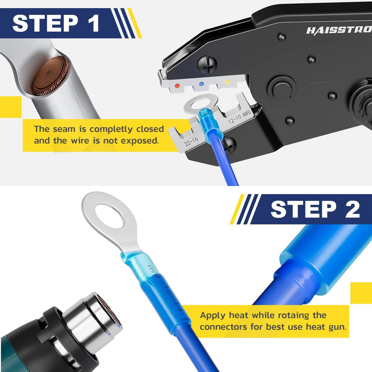
Order of operations: As mentioned, heat center (solder) first until you see it flow. You’ll notice the solder ring suddenly collapse and shiny solder spread out – that’s your cue. Then immediately move to the ends and heat them until you see the adhesive seep out. If you heat ends first, you might seal air inside that expands or, worse, if the solder hasn’t melted, the wires could slip out under the shrinking force. So always do solder first, then tubing ends.
-
Tug test after cooling: Let the splice cool naturally (it only takes maybe 30 seconds). Don’t shock-cool it with water or air; let the solder solidify slowly. Once cool, give a firm tug on each wire. A proper splice will “fail the wire before the joint”, meaning if you pull hard, the insulation will stretch or the wire might break elsewhere, but the joint will hold. If it slips out, then either it was the wrong size (too large) or not heated properly. It’s better to discover that now than later. Fortunately, this is rare if done right.
-
Storage: Keep your connectors dry and clean before use. If they sit in a hot car or in sunlight, the tubing or solder can degrade slightly over time. Also, avoid getting oil or grease on them (wipe wires clean if they were oily, as that can affect solder wetting). A good kit comes in a sorted organizer or bottle that keeps each size separate and protected.
-
Practice on a spare wire: If you’re new to them, sacrifice a couple of connectors on test wires. It helps you gauge heat and timing. Cut them open afterward to inspect how well the solder penetrated.
-
Don’t double-up wires into one end improperly: If you need to join three wires (like two into one), note that these connectors are mainly for two-wire splices. It is possible to put two wires twisted together into one side and one on the other, but it gets crowded and the solder may not evenly flow into all. For multi-branch joints, consider using a proper splice block or crimp cap, or do two serial splices. There are also specialty 3-way solder seal connectors (with a center wire through design), but those are less common.
-
Use quality connectors: Last tip – not all solder seal connectors on the market are equal. Cheaper ones might skimp on flux (harder to get a good flow) or use lower purity solder or tubing that doesn’t shrink right. A reputable brand will have evenly sized solder rings, clearly marked color coding, and melt smoothly (typically these use a Sn/Pb solder with a low melting point ~138°C if it includes bismuth, or ~178°C if standard 60/40 tin-lead). If you find connectors that require an inordinate amount of heat or the solder doesn’t ever get shiny, they might be poor quality. This is why looking for UL listings or at least good reviews is wise. Some brands even provide specifications like tensile strength of the splice or environmental test results. When in doubt, stick to connectors known to be used in automotive/marine contexts, not just any random bulk pack.
Hopefully these FAQs address the core concerns. Using solder seal connectors becomes straightforward once you know their strengths and limitations. They can produce professional, neat wiring repairs or additions very quickly – a big reason they’ve grown in popularity among DIY enthusiasts and professional electricians alike.
👉 One step to pro: Haisstronica solder and heat shrink sleeves.

Conclusion: Planning Your Kit Purchase
Choosing the right gauge mix in a solder-seal connector kit ensures you won’t be caught without the proper connector in the middle of a wiring job. Start by evaluating the common wire sizes in your projects (e.g. automotive wiring connectors will skew towards mid-range gauges, while electronics might need more small-gauge connectors). Select a kit that covers all the wire gauges you anticipate (typically AWG 22–10 for general use) and has proportionate quantities – more of the frequently used sizes, fewer of the rarely used ones. We’ve seen that a balanced 22–10 AWG kit often includes something like 50–60 pieces of the red and blue connectors each, and maybe 15–20 pieces of the yellow, with the rest white for thin wires. This kind of distribution matches real-world usage for many users and avoids waste.
Remember that quality matters: invest in marine-grade heat shrink solder connectors with dual-wall adhesive and clear tubing, so every splice is robust and inspectable. A well-made solder connector yields a connection that is electrically sound, mechanically secure, and sealed against the elements – effectively giving you the benefits of solder and a weatherproof seal in one go. Used in the appropriate scenarios, these connectors will save you time and prevent future headaches (no one likes tracing an intermittent connection or corroded splice in a bundle of wires!).
In summary, consider this checklist when buying:
-
Gauge Coverage: Does the kit include all the AWG sizes you need (and maybe a bit beyond, just in case)? For most, a 26–10 AWG full-range kit suffices. If you regularly do heavy gauge (8 AWG, etc.), you’ll need other solutions beyond solder sleeves for those.
-
Quantity Mix: Are there enough mid-gauge connectors (the ones you’ll use most)? It’s better to have a surplus of a certain size than to run out and be forced to use an incorrect size. If a kit is, say, 100 pieces but mostly tiny ones you never use, it’s not as good as a 100-piece kit with the right mix. Don’t be swayed by pure numbers; look at the breakdown.
-
Quality & Certifications: Look for mentions of standards or test results. For instance, compliance with UL, IPC/WHMA-A-620 (a cable harness assembly standard), or automotive SAE specs can be a green flag, indicating the product was made to meet certain criteria. One should also trust user reviews and possibly independent tests (there are videos and articles where people stress-test these solder connectors).
-
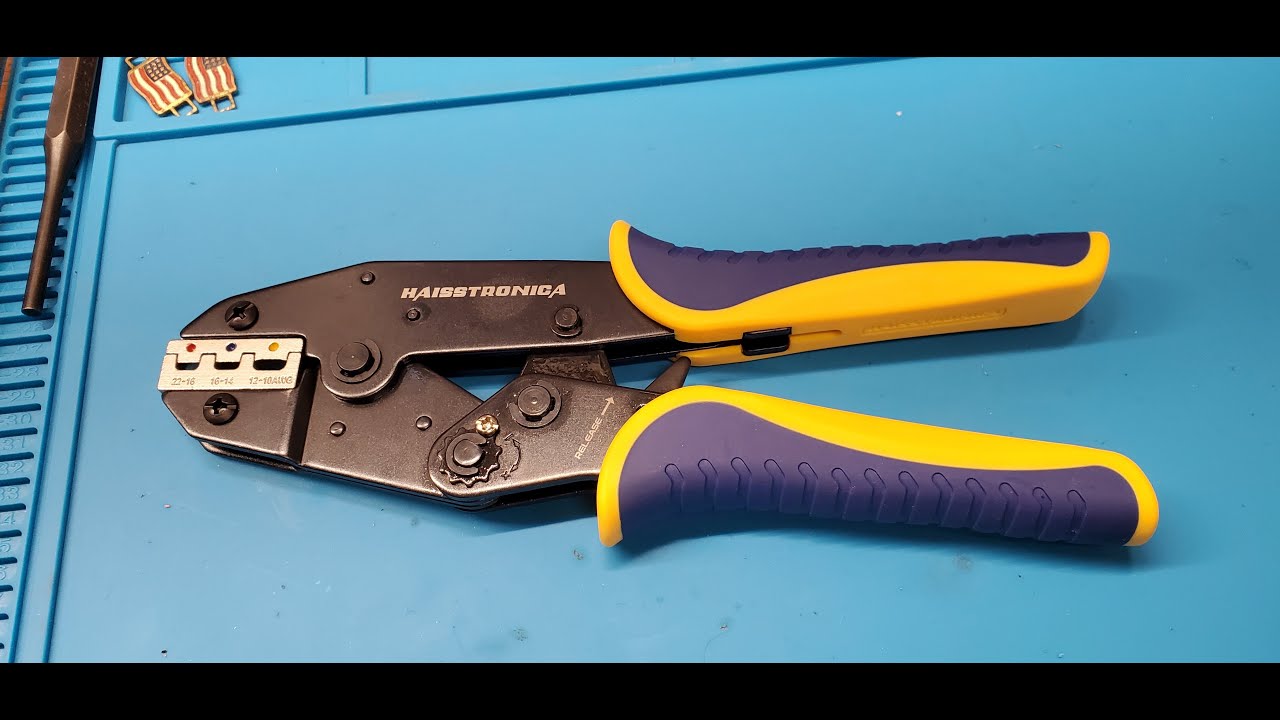
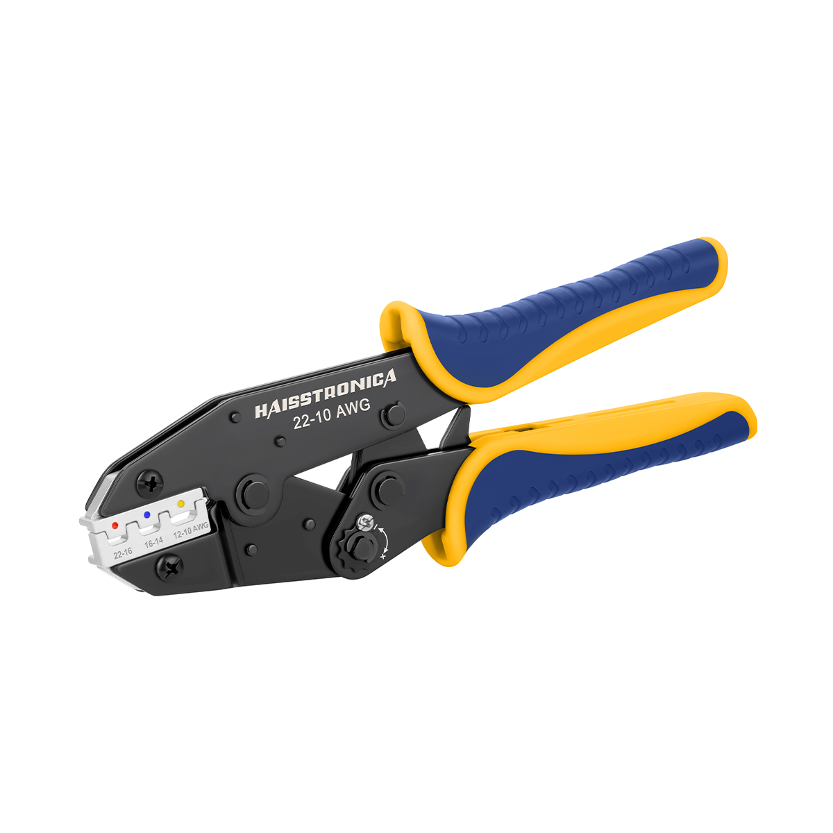
Tools to accompany: Ensure you have a proper heat gun in your toolkit to maximize the connectors’ performance. Some kits bundle a heat gun or at least a good storage case – those are nice extras to consider for value.
-
Alternatives on hand: While building your wiring toolkit, it’s wise to also have a stash of traditional crimp & seal connectors for those cases where crimping is preferable (e.g., ring terminals, or splicing when you can’t apply heat safely). This doesn’t mean you expect the solder seals to fail – it just means you’re prepared for all types of jobs. Think of it like having both a flat-head and Phillips screwdriver – different tasks need different tools.
By following this guide and planning ahead, you’ll purchase a connector kit that covers your needs without overstocking on useless sizes. The result is efficient, reliable wiring work. As the saying goes in wiring, “choose confidently and wire once” – meaning if you pick the right materials and do it right the first time, you won’t have to redo it. With a well-chosen solder seal connector kit and the knowledge of how and where to use it, you’re set for many successful wiring projects to come. Happy splicing!
Our Top User-friendly Picks
From bilges to engine bays, solder and seal connectors keep water and corrosion out. Each solder seal connector distributes heat evenly, flows solder, and seals in one pass. Use heat shrink connectors with solder to streamline workflows and reduce rework.
👉 Try Haisstronica solderless connectors when speed matters most.

References: