


The safest crimp starts before the tool closes.
Isolate the power, verify the circuit is dead, and match the wire, connector, and die. Then strip cleanly, complete the crimp cycle, inspect the connection, and add the protection the job requires.
A ratchet click, a continuity beep, or a heat-shrink sleeve is not proof of a safe connection on its own.
1. Disconnect power—and verify before touching conductors
Crimp only on de-energized conductors. Identify every supply, including batteries, chargers, backup power, and stored energy. Follow the equipment's isolation procedure and prevent someone else from reconnecting it.
Isolation is a check, not an assumption
- 1Use a voltage-detection instrument and test method suitable for the circuit, voltage, and measurement category. Follow the required safe-isolation procedure.
- 2Prove the instrument works before and after verifying the work area is dead. A failed or incorrectly selected tester can give a misleading result.
- 3Secure the work area, wear appropriate eye protection, and keep fingers outside the die and cutter. Grippy handles do not establish a tool's live-working insulation rating.
Stop if you cannot establish safe isolation. Mains panels, EV/high-voltage systems, multiple supplies, and unfamiliar equipment need a suitably qualified person. This guide is not a live-work procedure. For proving dead, do not rely on a single-pole or non-contact indicator alone. HSE GS38 explains the distinction.
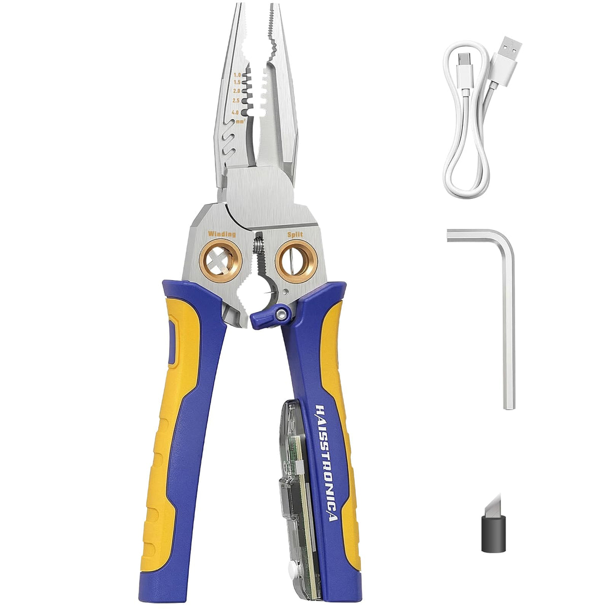
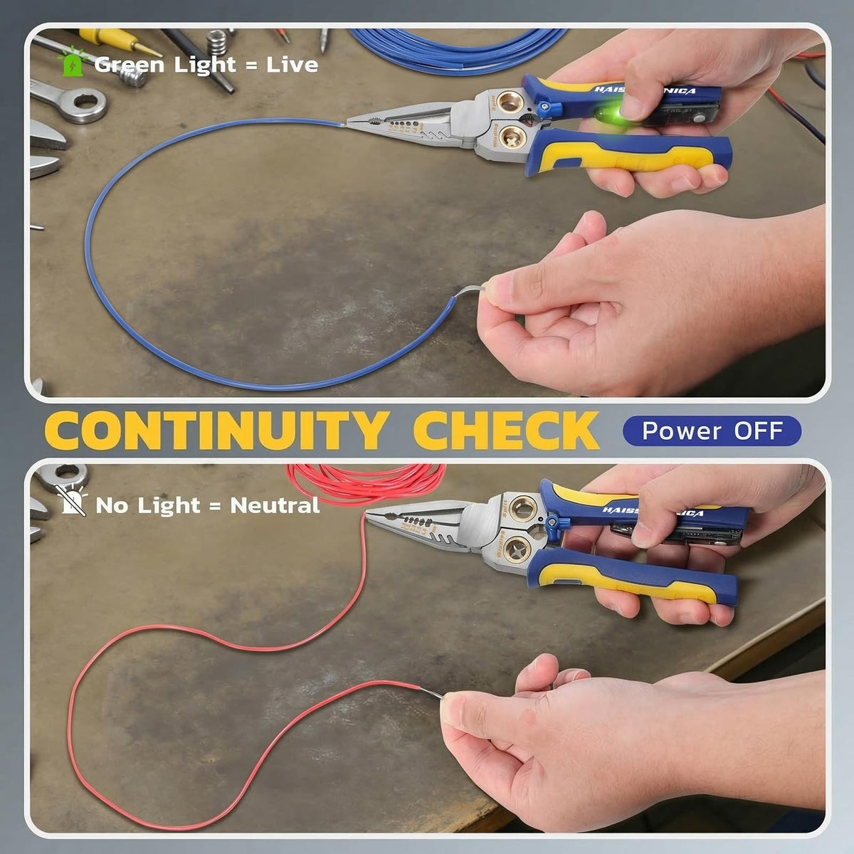
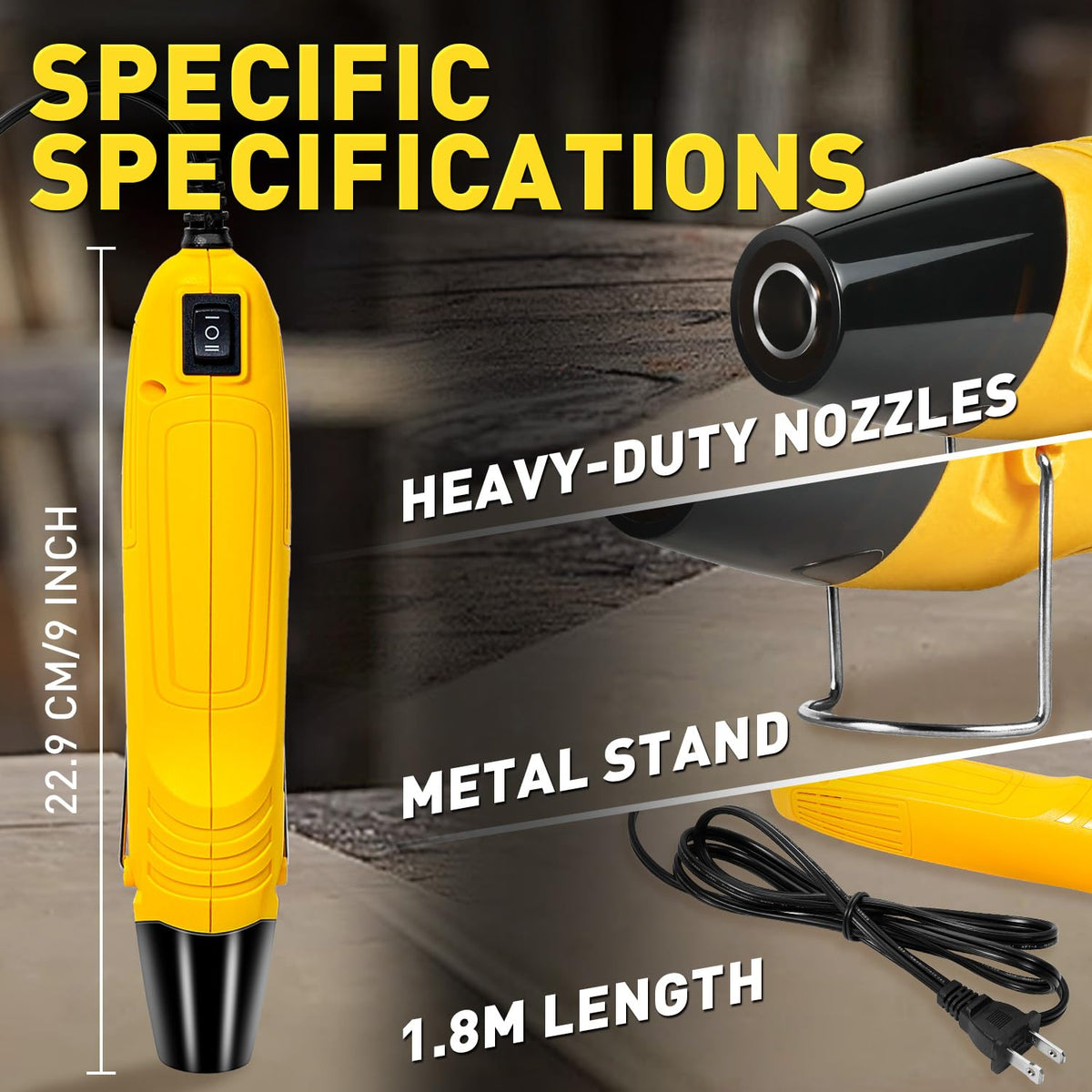
9-in-1 Wire Stripper with Voltage Tester

A combined preparation tool with a built-in voltage-indication feature and stripping positions listed for 18–10 AWG. Review the exact testing mode and instructions before choosing it.
It is not presented here as a two-pole proving-dead instrument. A quiet indicator does not authorize you to cut or crimp a wire.
2. Match the connector to the wire and the job
Read the terminal's documented conductor range, material, strand class, insulation limits, and application ratings. The barrel must be approved for the actual conductor—not merely look like the right color.
Wire size and construction
Confirm AWG or cross-sectional area and whether the wire is solid, stranded, or fine-stranded. Do not trim strands, fold a small conductor, or combine wires to make an unapproved fit. Copper, aluminum, and factory tin-plated wire are not interchangeable without a listed combination.
Connector shape and location
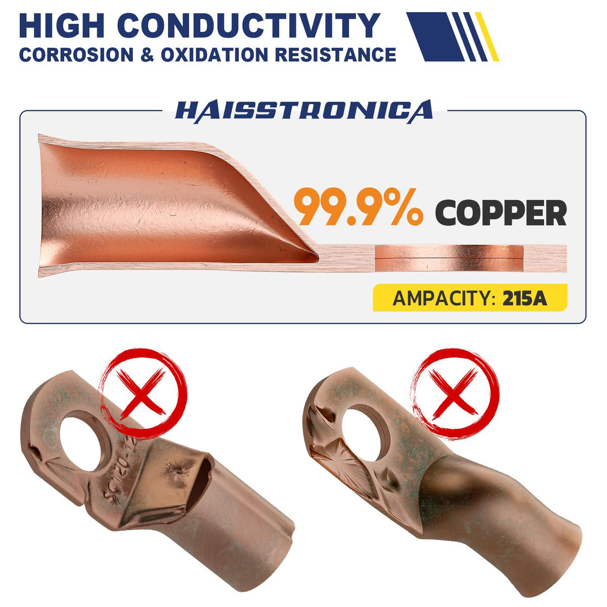
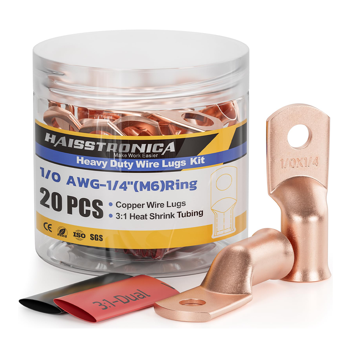
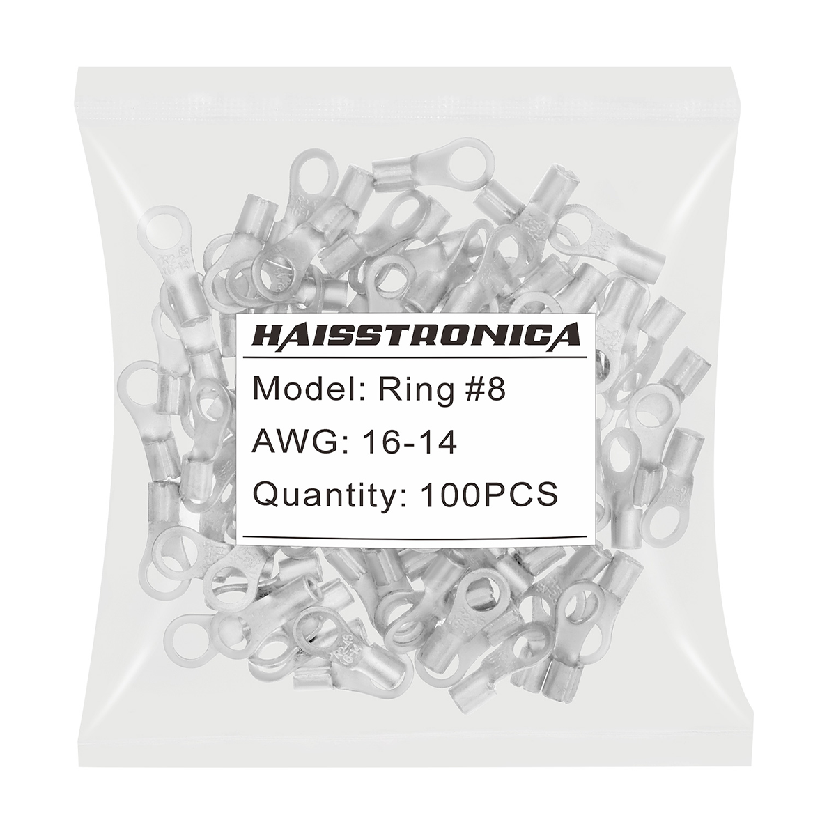
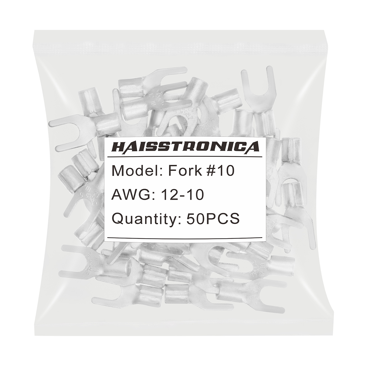
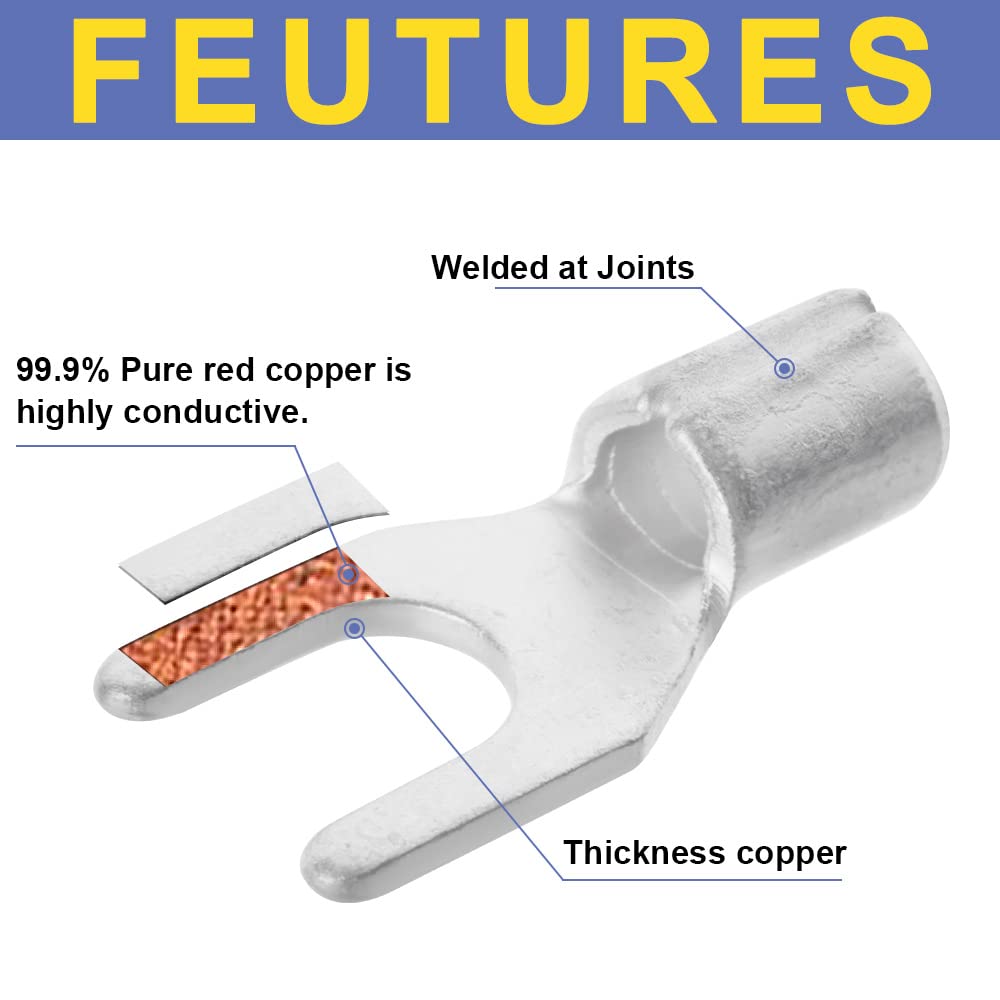
Choose a butt splice for a permitted inline joint, a ring or fork for the correct stud connection, a ferrule for a compatible terminal block, or an open-barrel contact for its housing. Confirm voltage, temperature, current/application, moisture exposure, and any required approval.
No universal color rule: color coding is a helpful cue, not a substitute for the printed range and connector instructions. Do not assume an insulated-terminal die also works on heat-shrink terminals, ferrules, or open-barrel contacts.
3. Set strip length for the conductor barrel
Use the connector manufacturer's strip-length specification. Relate it to the conductor barrel—not the whole plastic sleeve or a separate insulation-support section. There is no single safe strip length for every terminal.
- ✓Cut back to clean, undamaged wire and set the stripping stop to the required length.
- ✓Test the setting on an offcut of the same wire. Remove insulation without nicking, stretching, or cutting strands.
- ✓Inspect before insertion. If the conductor is damaged, cut back and prepare a new end; do not hide damage inside the sleeve.
Do not add solder to “strengthen” the prepared end. Follow the terminal specification; pre-soldering stranded wire is not the same as factory tin-plated strands. Neither extra solder nor a second squeeze repairs a mismatched termination.
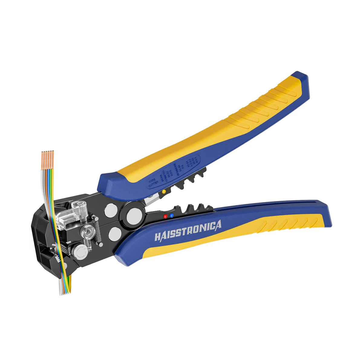
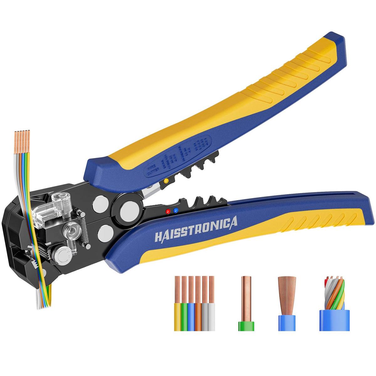
Self-Adjusting Wire Stripper · AWG 24–10
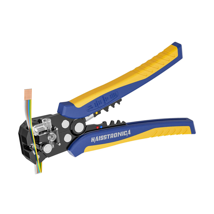
For compatible insulation within its documented range, the self-adjusting jaws reduce repeated slot selection. Set the strip length and fine-tune tension on a sample before preparing the final wire.
Continue only when the exposed conductor is intact and the length suits the connector.
4. Match die geometry before applying force
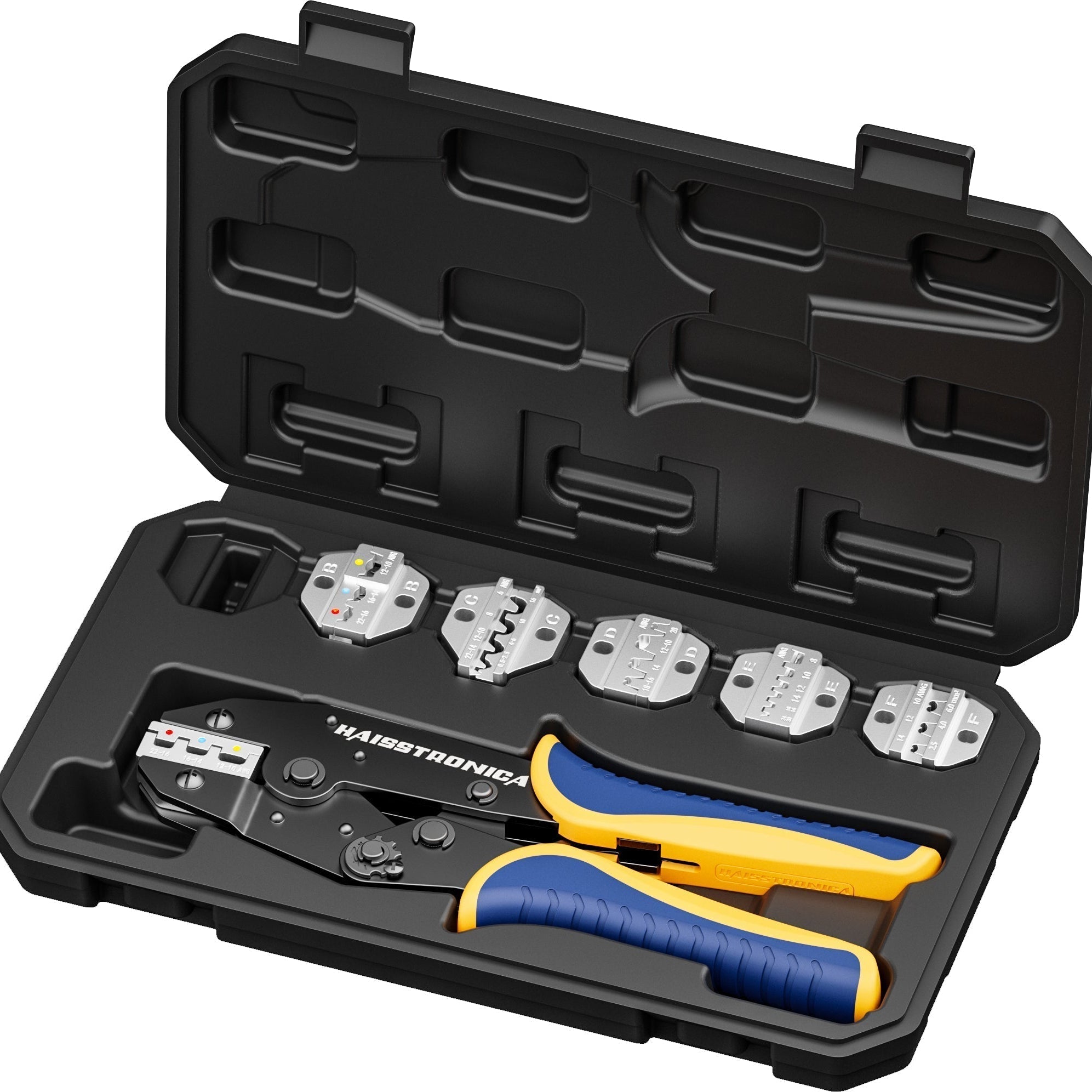
Check the exact connector family and wire range against the tool's instructions. Position and orient the barrel as specified; keep the wire fully seated. Inspect the die for damage, debris, or misalignment before the job.
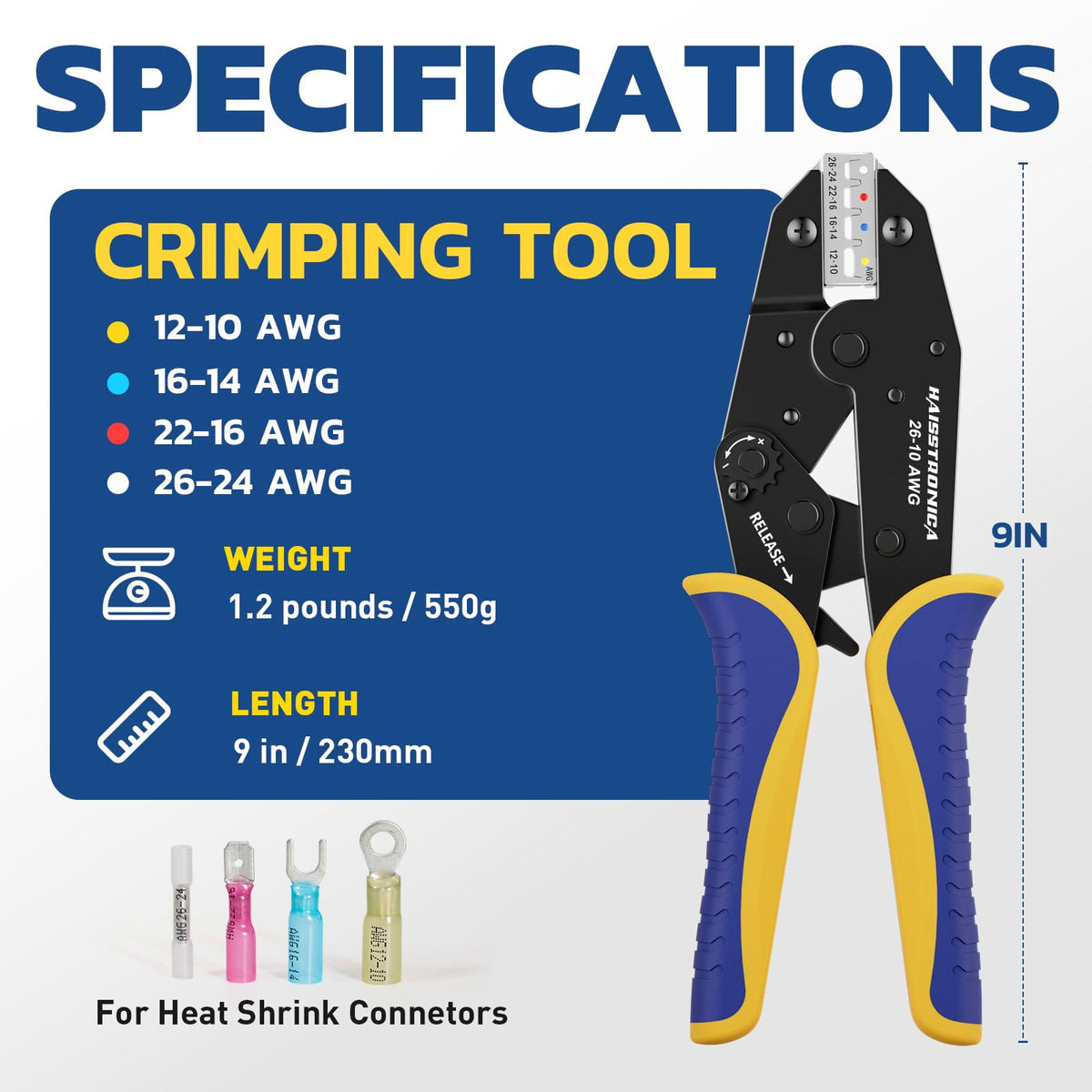
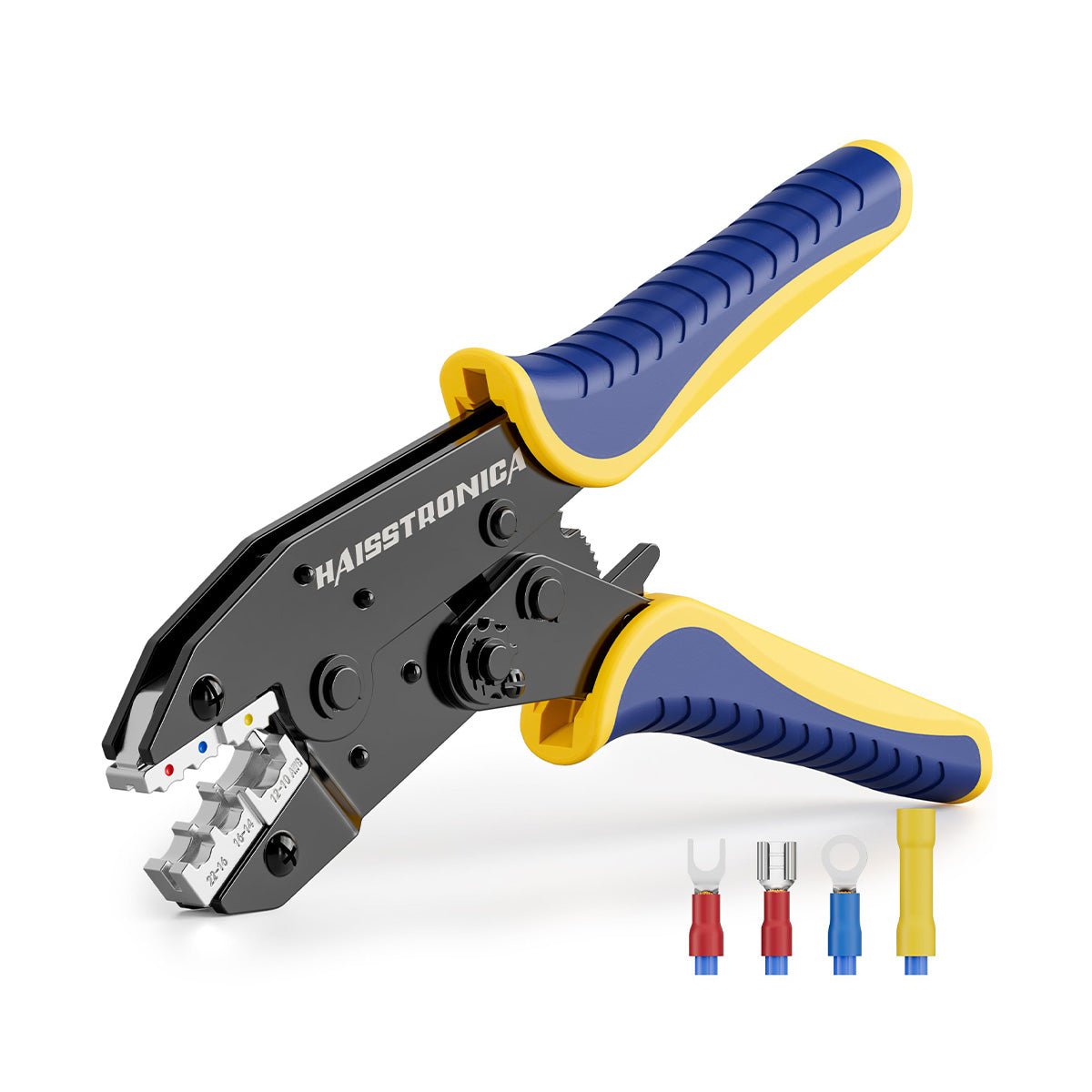
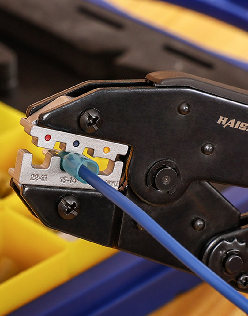
Compatible heat-shrink terminals · AWG 22–10
A dedicated heat-shrink-terminal ratchet tool is the relevant route when both connector geometry and conductor size match. The broader range of an assortment does not expand the tool's capacity.
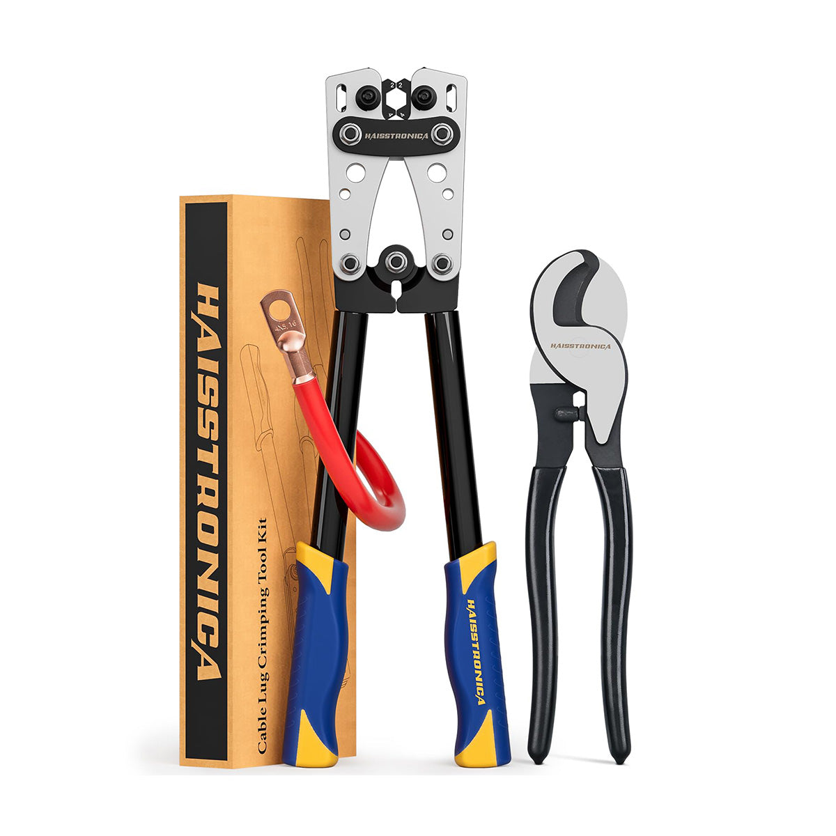
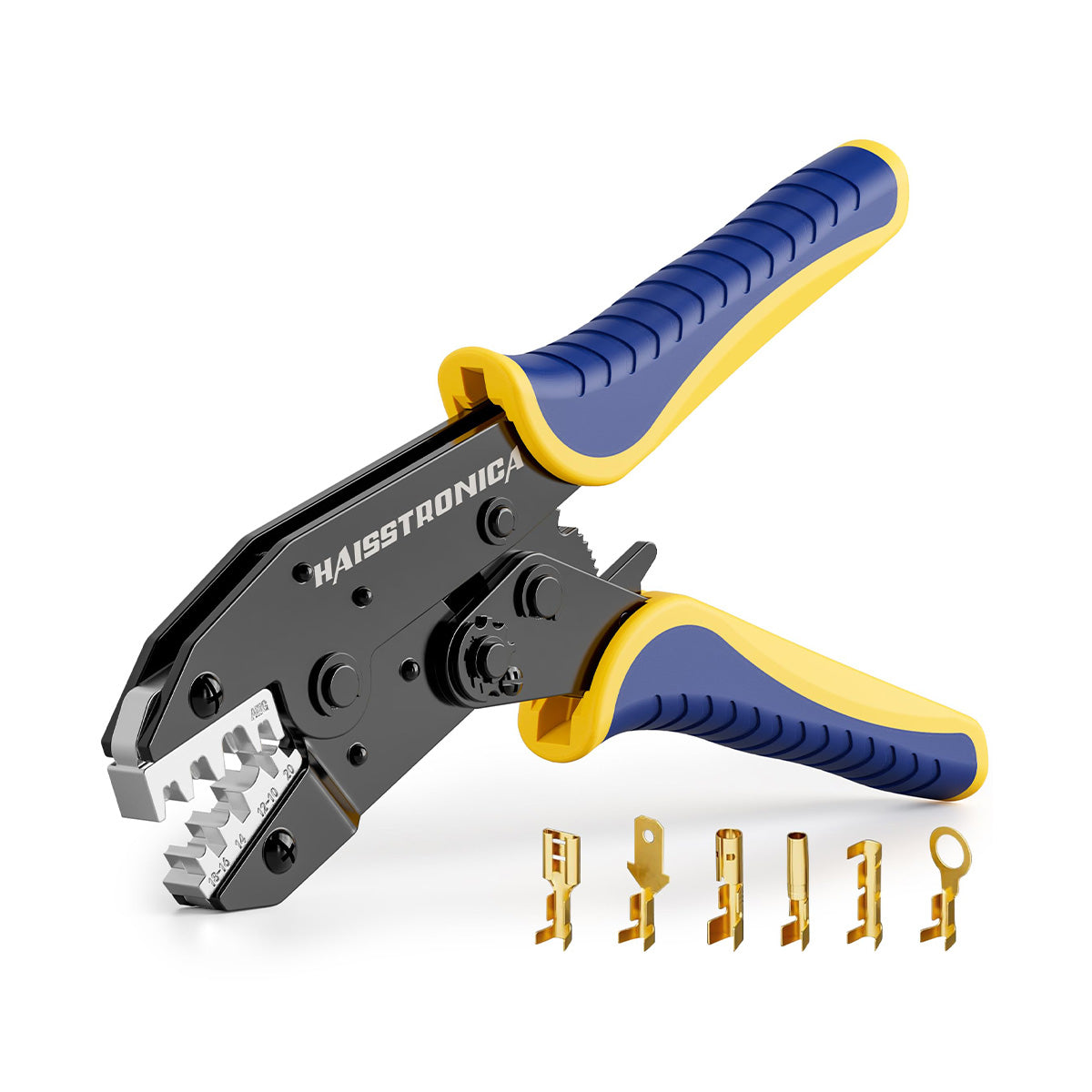
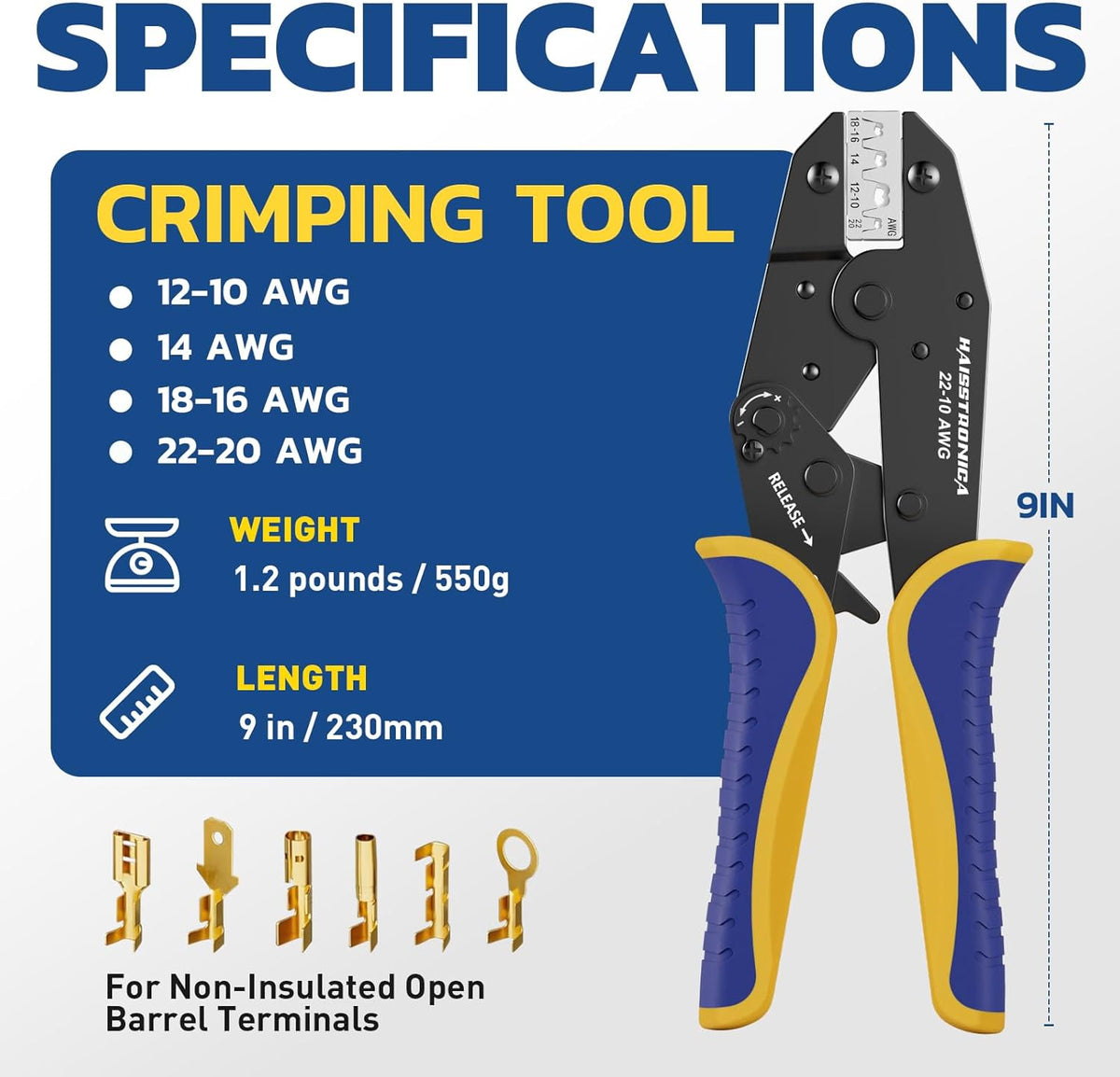
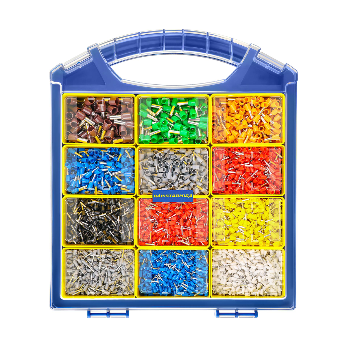
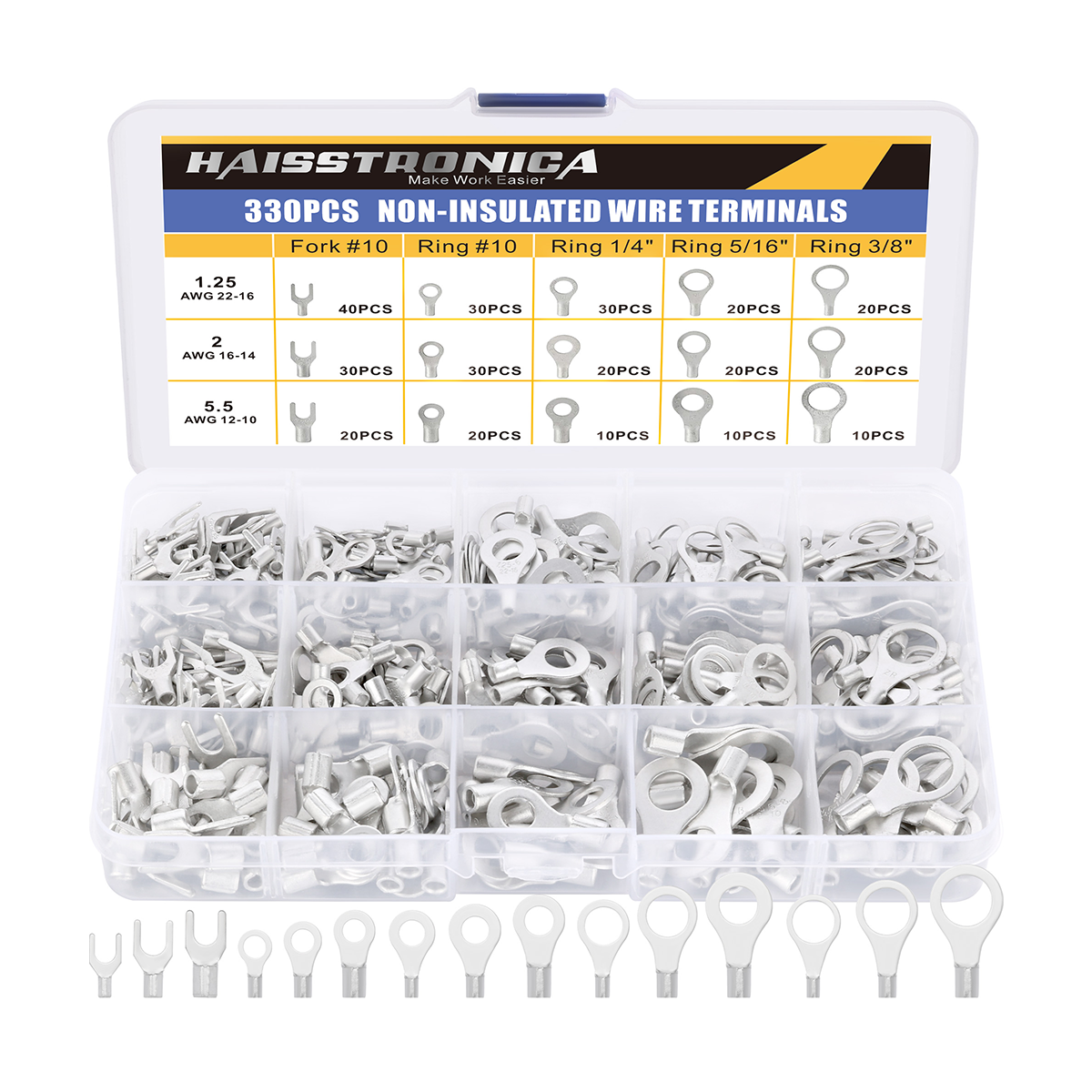
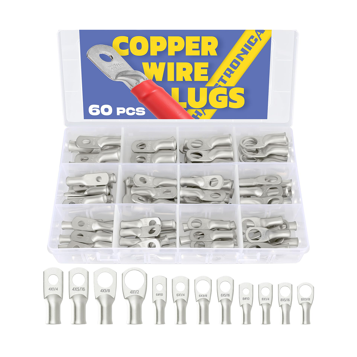
Ferrules, open barrel, non-insulated terminals, or large lugs

Choose the corresponding die and tool. A ferrule profile, an open-barrel forming die, and a lug crimper do different jobs. If you cannot establish compatibility, stop and identify the terminal before buying or squeezing.
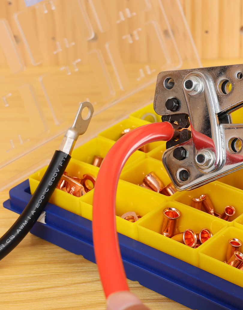
Shown: a ferrule crimper. Other terminal types require their own compatible tool and die.
5. Complete the specified crimp cycle
Hold the connector and wire in alignment and close the matched tool through its normal cycle. A ratchet helps prevent an incomplete ordinary stroke; it does not verify the connector, wire, die, or finished crimp.
If the wire slips, the tool jams, or you use the emergency release, treat the termination as incomplete. Follow the tool's release procedure and the terminal maker's rework rules. Do not make extra bites or increase pressure simply to hide a poor fit.
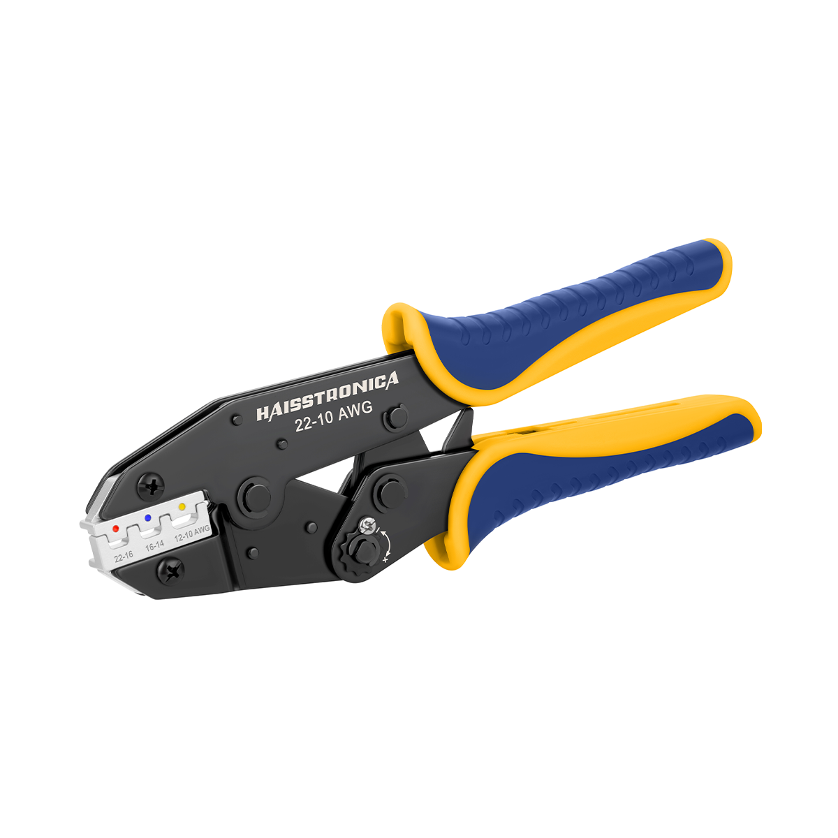
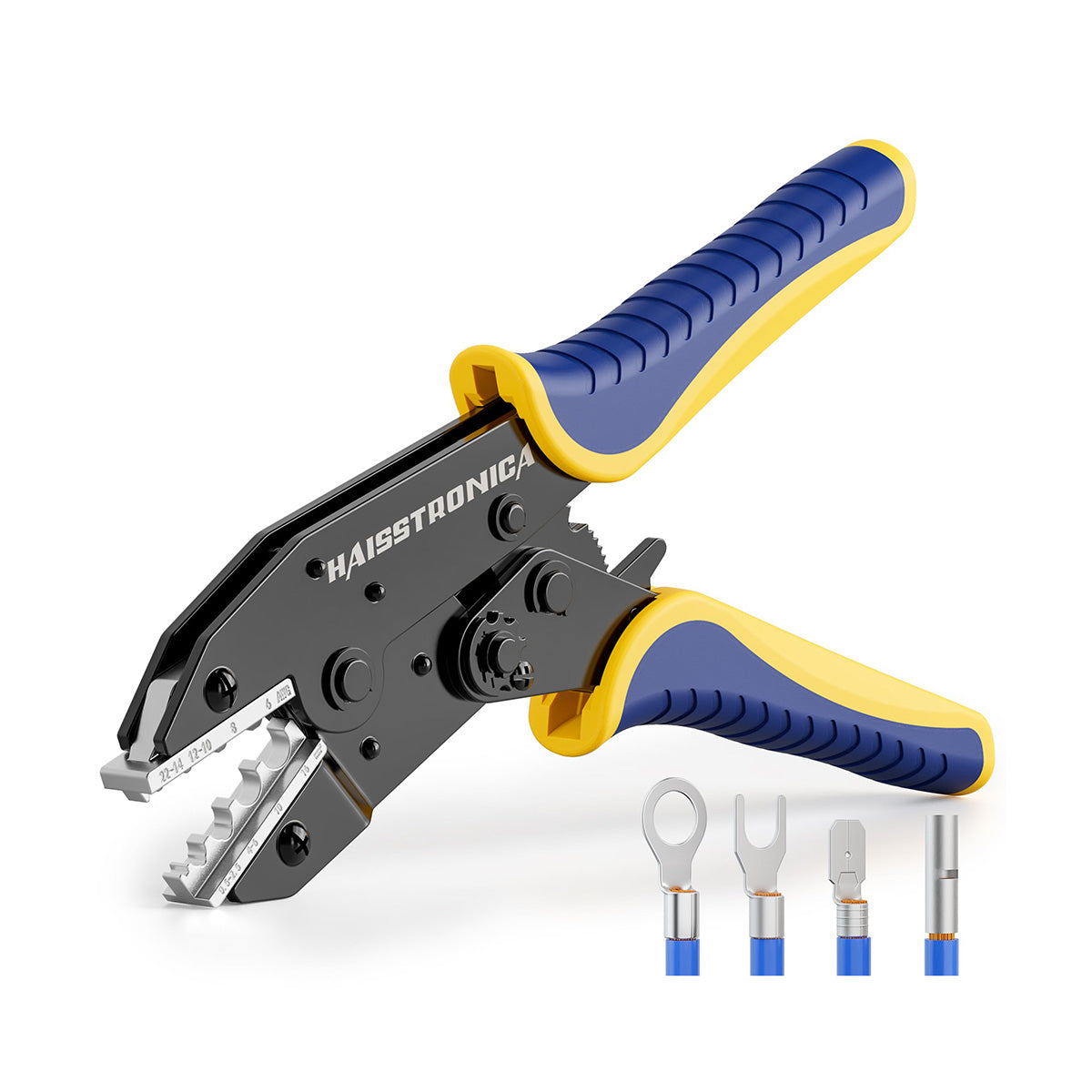
AWG 22–10 Ratchet Crimping Tool
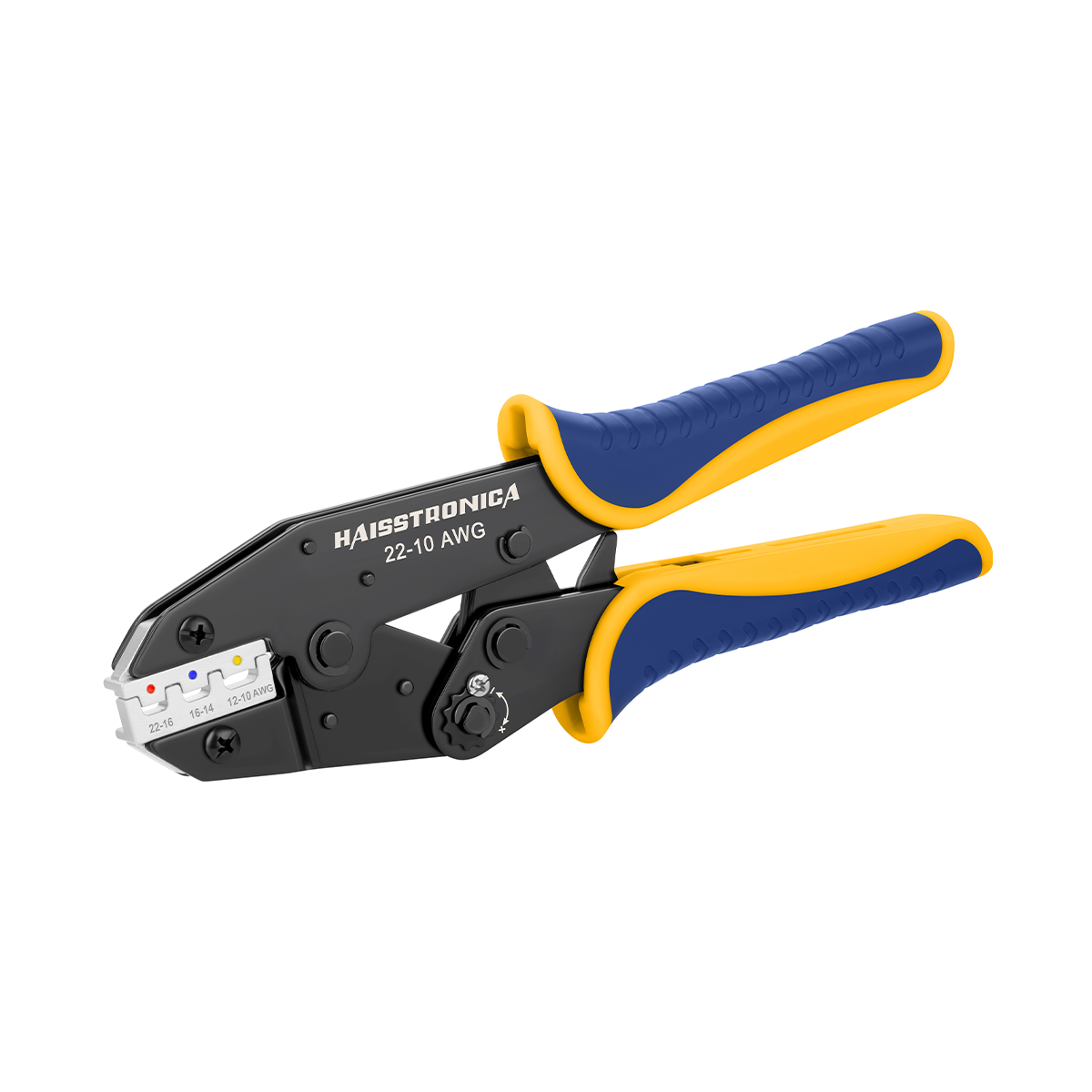
A dedicated option for compatible heat-shrink connectors. The ratcheting action completes a controlled stroke, with a release feature for repositioning.
Match the die cavity and connector instructions, then inspect the result. Full cycle is a process step—not a safety certificate.
6. Inspect and test—do not stop at a click
Visual and dimensional checks
Look for complete insertion, captured strands, intact insulation, and a correctly formed barrel. Reject cracked sleeves, stray strands, cut wire, and distorted contact areas. Conductor brush, bellmouth, insulation position, and crimp height are connector-specific—not one universal “copper flush” rule.
Mechanical checks
Use the retention check specified for the connection. A gentle hand check can reveal gross looseness but cannot establish the required pull strength. Where qualification is required, use the specified force test and sampling method; do not install destructively tested samples.
Electrical checks
With the circuit isolated and stored energy controlled, perform the specified continuity and short-circuit checks. Never use resistance or continuity mode on an energized circuit. A continuity beep alone does not prove acceptable contact resistance or load performance.
Complete insulation, sealing, and guards before any controlled energization. Live voltage-drop or load testing belongs in an appropriate test procedure, performed by someone qualified for the system.
If a check fails, stop and remake the joint. Find the cause—wire damage, wrong barrel, incorrect die, incomplete insertion, or tool condition. More heat, tape, or an extra crimp is not a substitute for a sound termination.
7. Add the environmental protection the joint requires
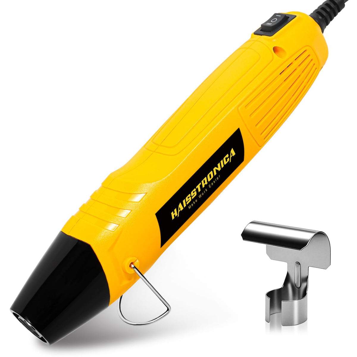
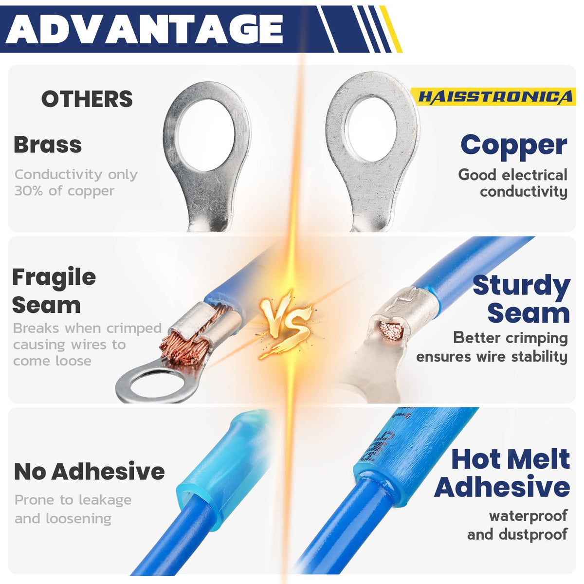
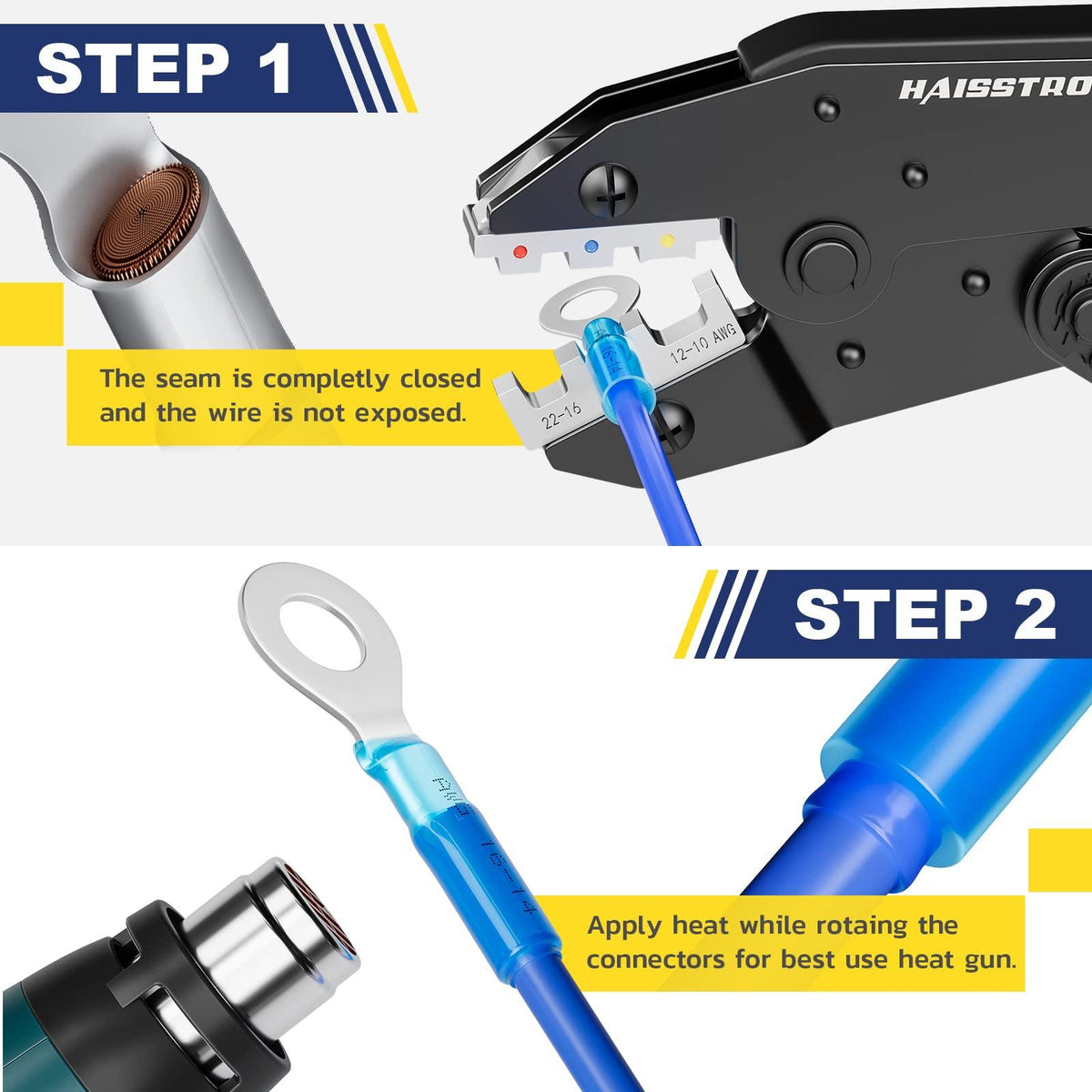
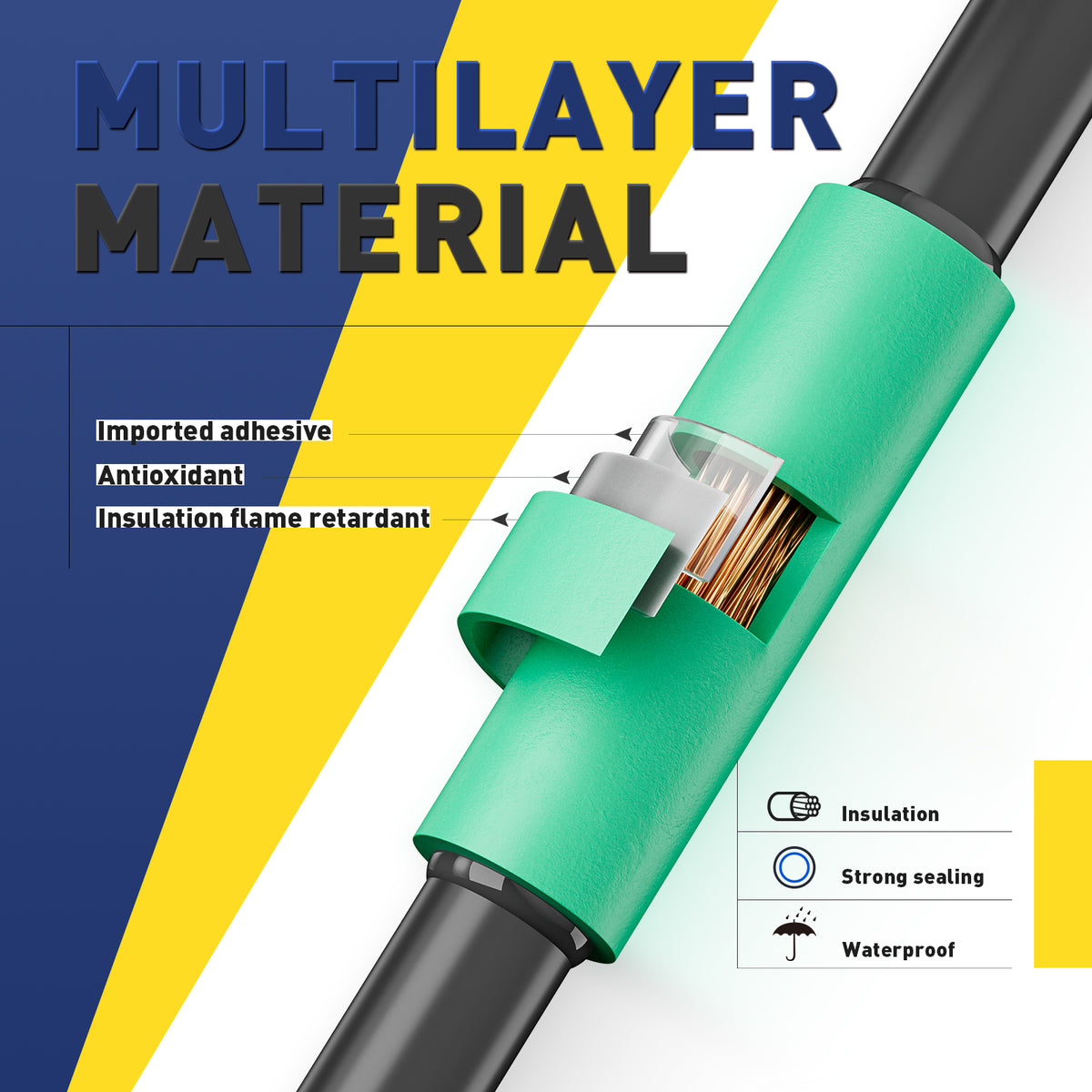
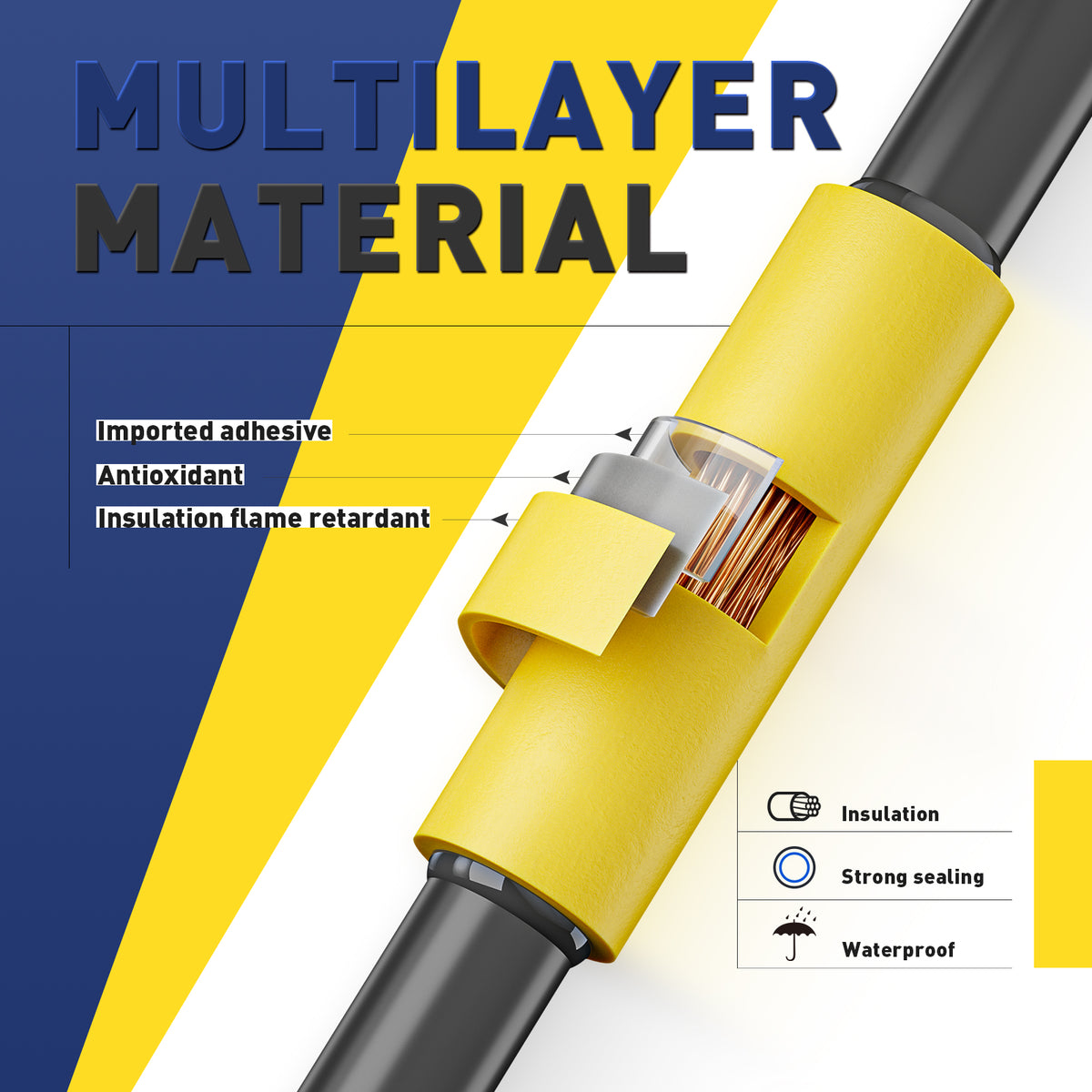
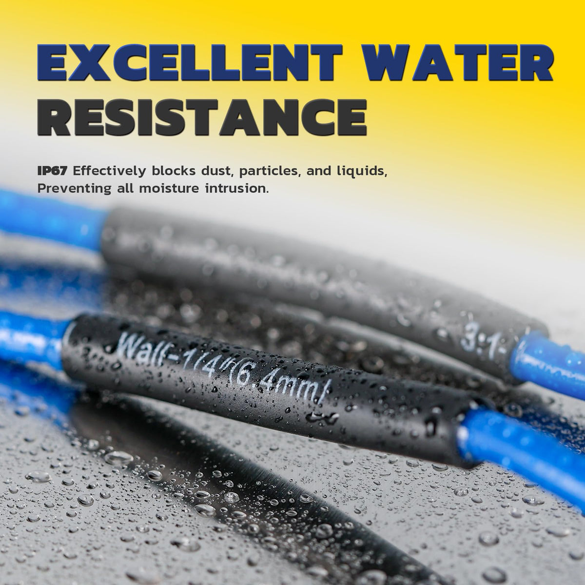
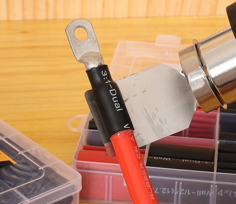
For a compatible adhesive-lined heat-shrink crimp connector, make and inspect the mechanical crimp first. Then apply controlled heat as directed, keep it moving, protect nearby insulation, and allow the joint to cool undisturbed.
Inspect the sleeve and end seals. Avoid scorching, splitting, or excessive adhesive loss. Provide strain relief and routing support so the connector is not carrying cable tension. Keep heat away from fuel, flammable vapors, and heat-sensitive parts.
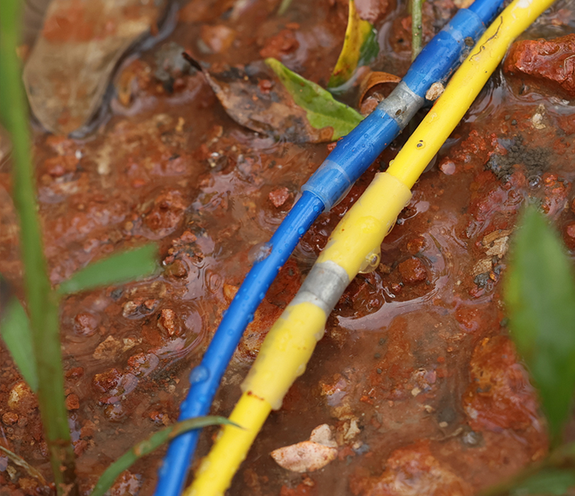
Sealed does not automatically mean approved for every wet location. Verify the complete connector system's suitability for immersion, direct burial, temperature, and the actual conductor combination. A solder-seal sleeve follows a different joining process; do not crimp it unless its instructions explicitly call for it.
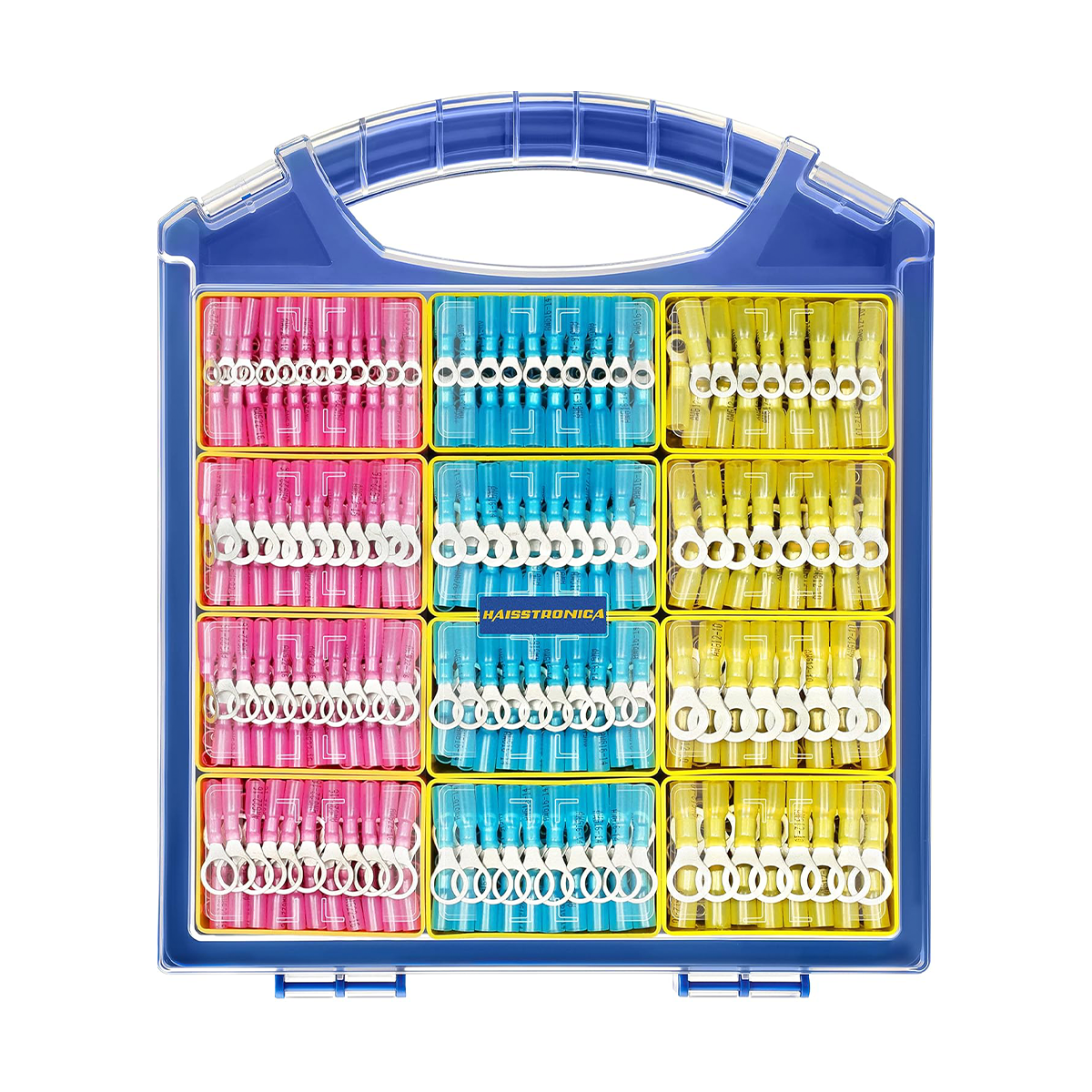
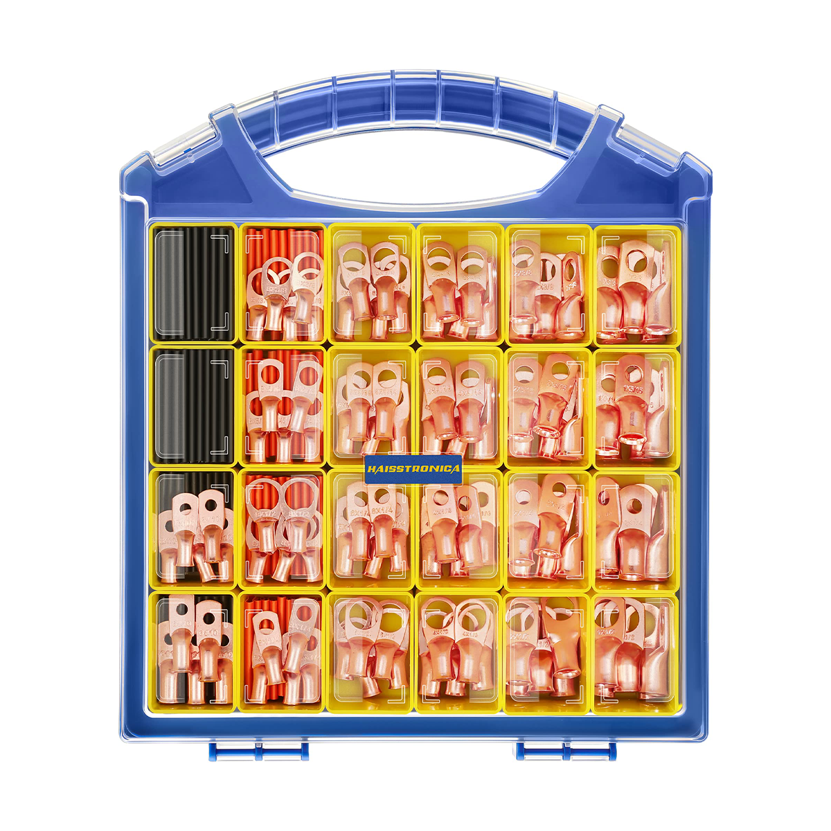
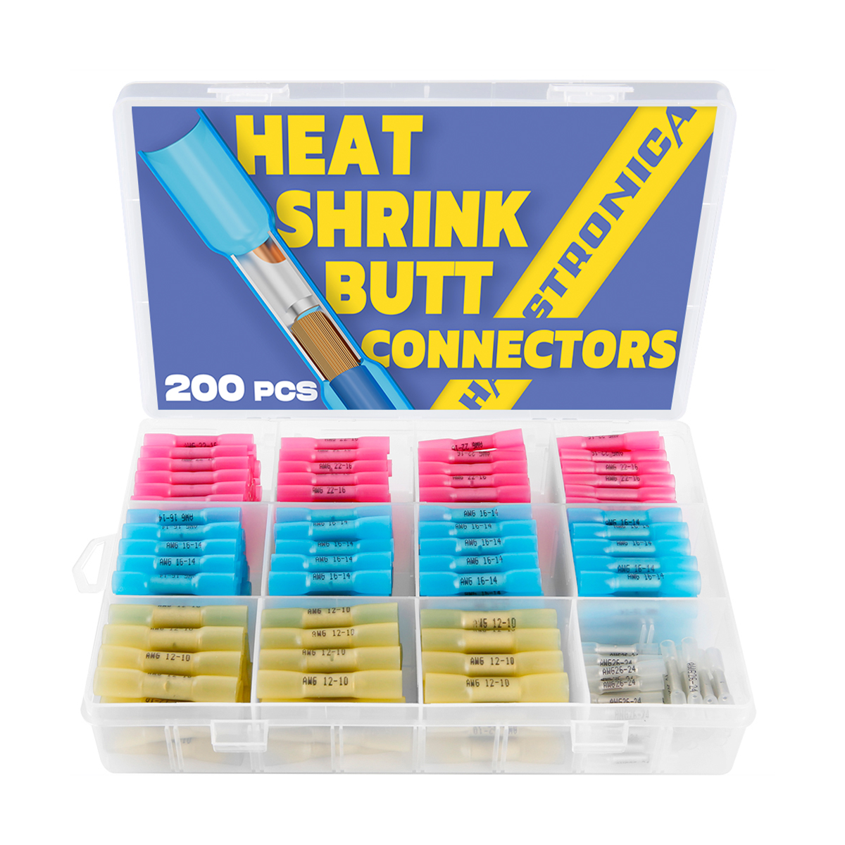
Choose a Heat-Shrink Connector Kit by usable sizes
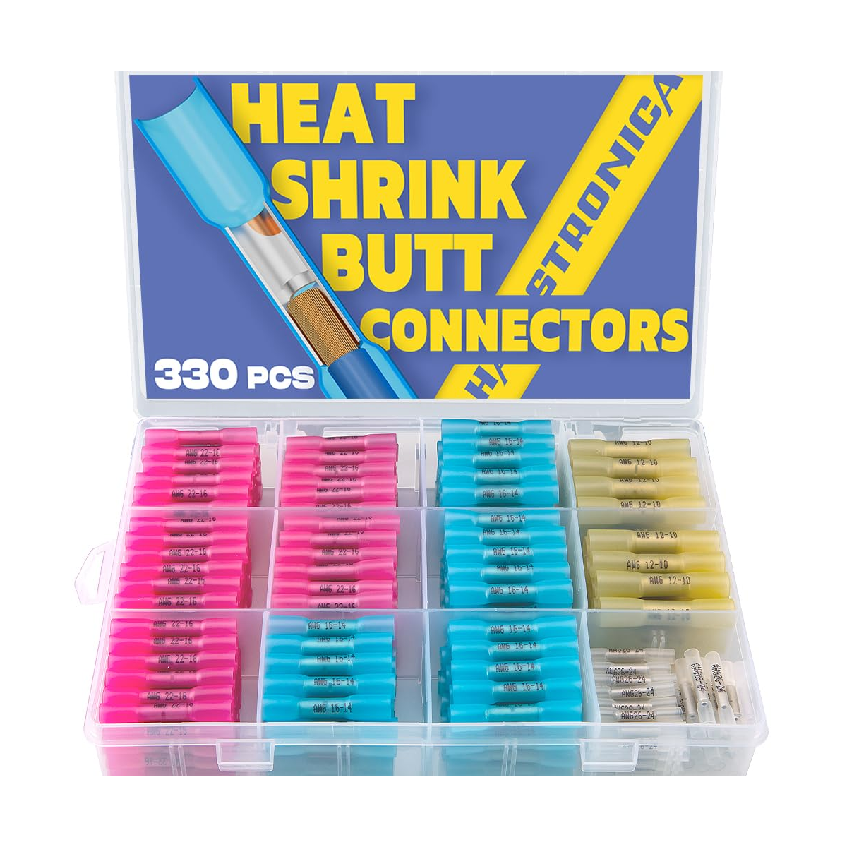
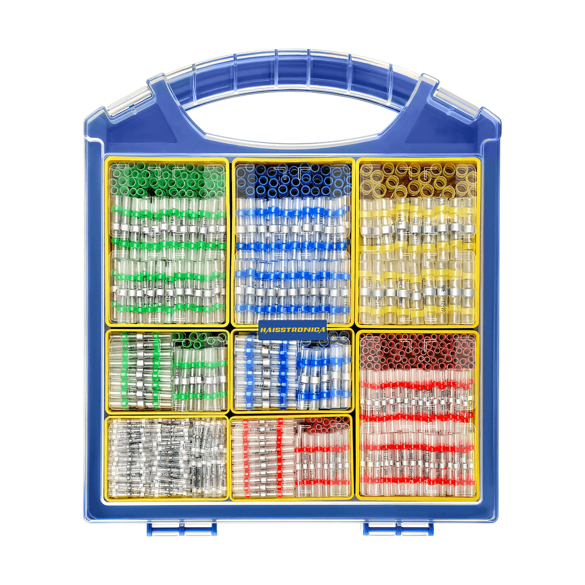
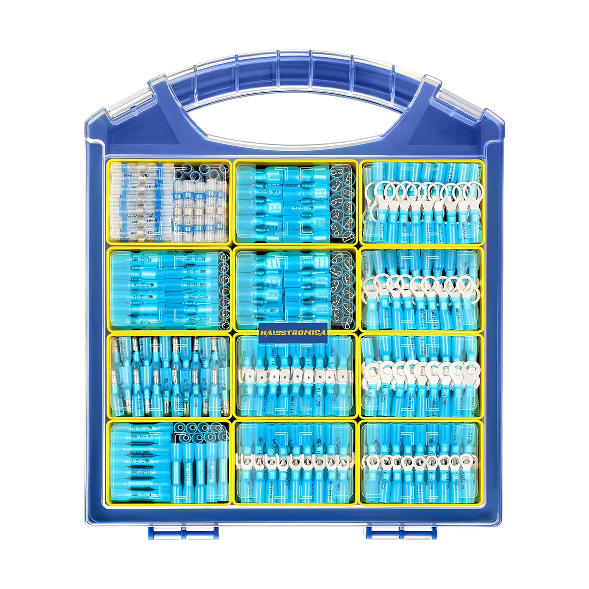
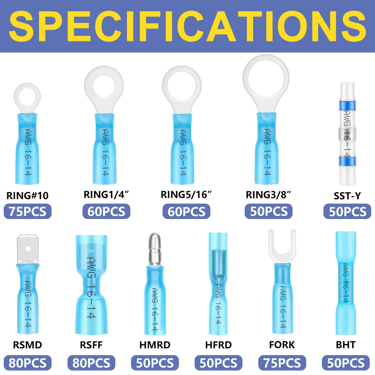
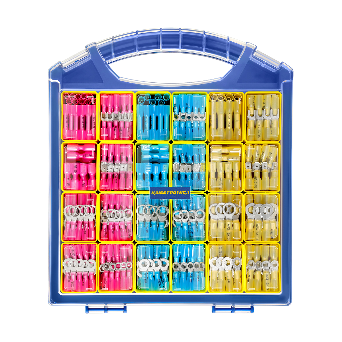
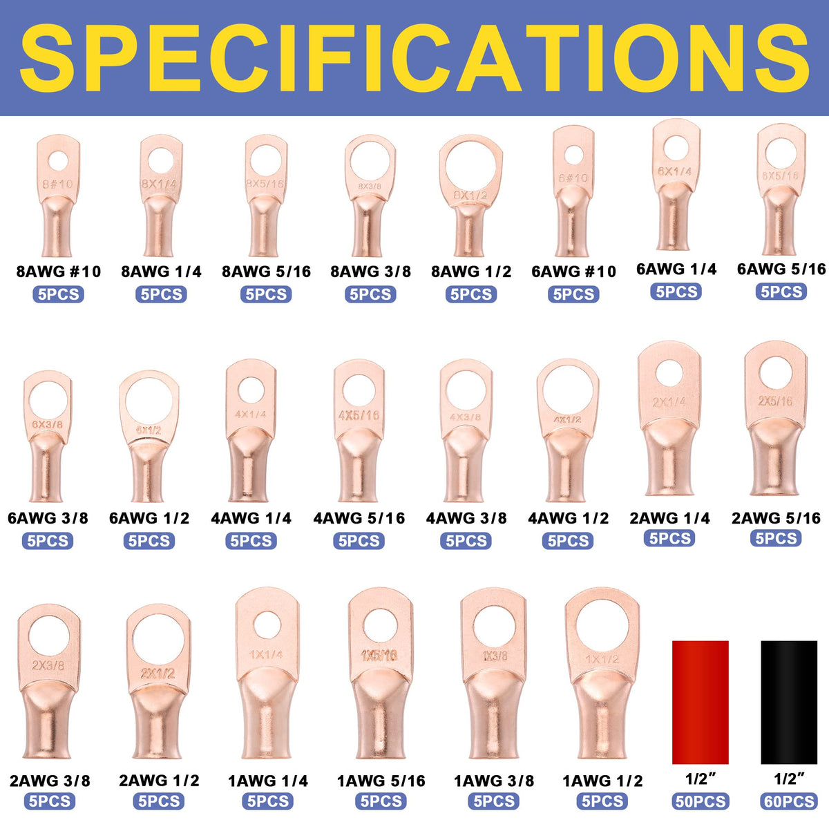
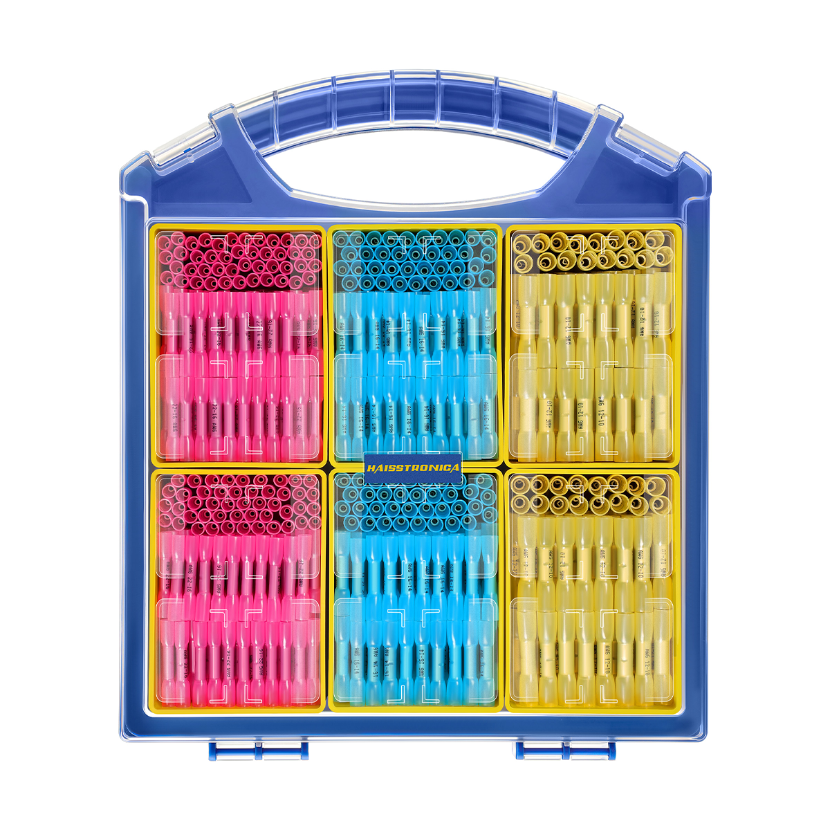
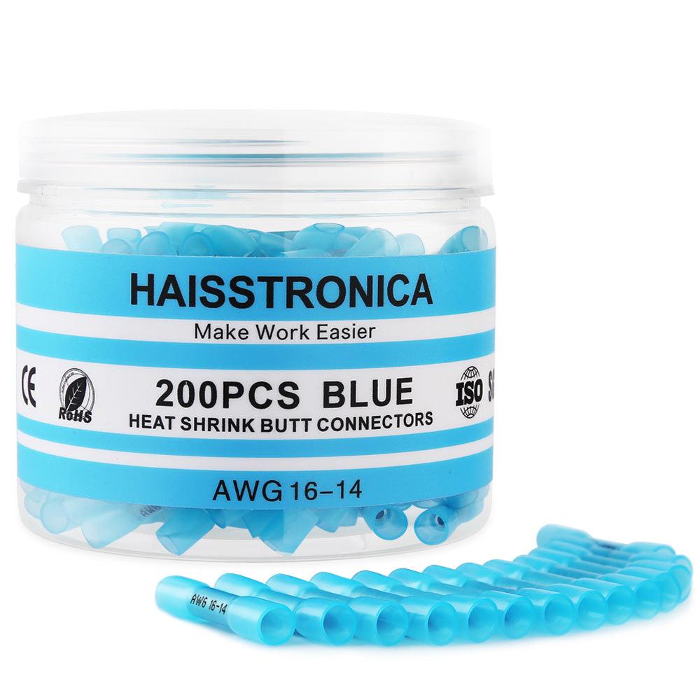
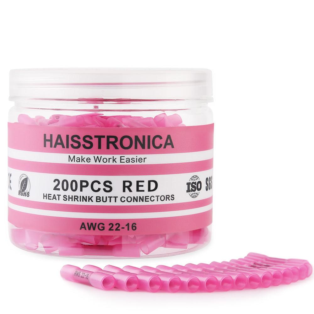
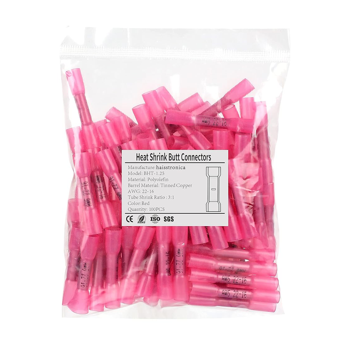
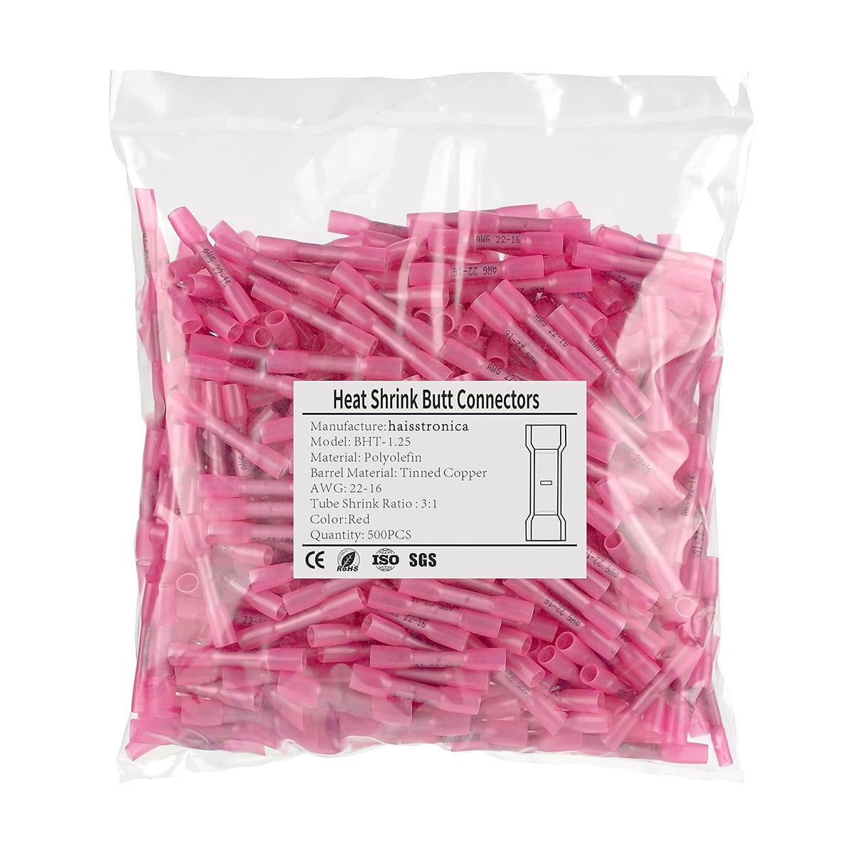
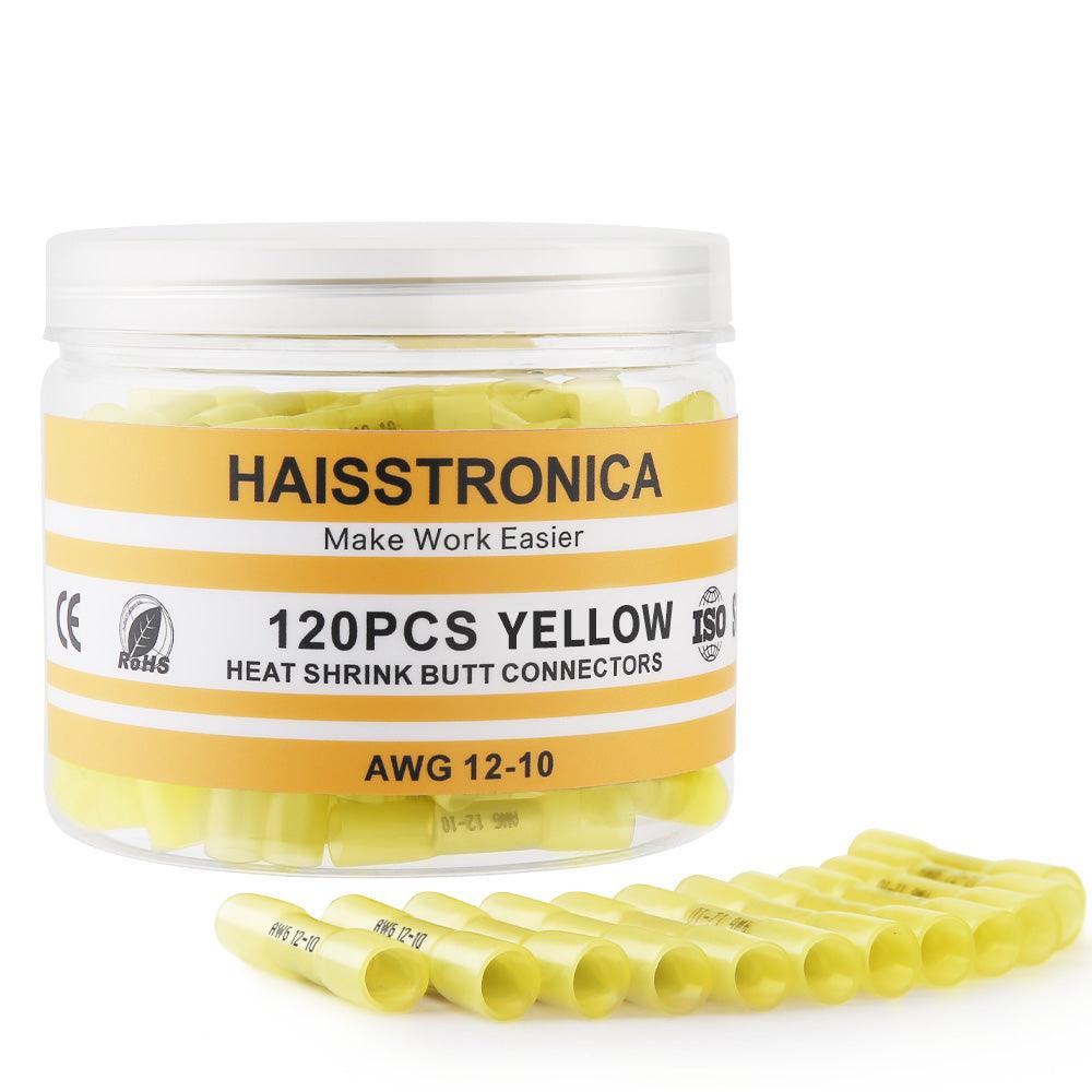
Look for the terminal shapes and wire ranges your job needs, then count the pieces in those sizes. A large assortment is not useful if the required barrel size is missing.
Browse the current heat-shrink terminal range and confirm the selected kit's stock and tool compatibility before ordering.
Image shows an example assortment. The link opens the product series so you can check current options.
Your safety tool checklist—not an automatic shopping cart
Keep tools that already meet the job's requirements. Add only the missing capability, and confirm compatibility before combining products.
Verify the work is safe to start
Suitable proving-dead equipment, an appropriate isolation method, and required protective equipment come first. The 9-in-1 indication feature is an optional supplement, not their replacement.
Review the 9-in-1 Tool →Prepare the conductor cleanly
A stripper that suits the wire and insulation, plus the connector's required strip length. Reuse your existing stripper if it consistently leaves undamaged conductors.
Check AWG 24–10 Stripper Compatibility →Form the correct terminal geometry
A matched crimper and die, serviceable jaws, and the connector's inspection criteria. Use the dedicated heat-shrink ratchet only when the combination fits.
Compare Wire Crimpers →Inspect, seal, and support
Appropriate inspection/test equipment, the required terminals, controlled heat where specified, and cable support. Check actual sizes and quantities rather than total kit piece count.
Choose Heat-Shrink Terminals →Safety is the sequence—not a single tool.
Isolation → compatibility → clean preparation → matched crimp → verification → appropriate protection. If any step is uncertain, resolve it before reconnecting power.
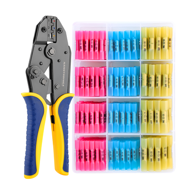
Common safety questions
Does a full-cycle ratchet guarantee a good crimp?
No. It helps complete the tool stroke. The wrong terminal, conductor, or die can still produce a bad connection after a full cycle. Match the parts and verify the finished joint.
Can the 9-in-1 tester prove that a wire is dead?
Do not use its indication feature alone for that decision. Use appropriate proving-dead equipment and the required safe-isolation procedure. Review the tester's documented mode, ratings, and limitations.
Is a tug test or continuity beep enough?
No. A hand check can expose looseness and continuity can detect an open circuit, but neither replaces the connector's specified dimensional, mechanical, and electrical acceptance checks.
Technical references
HSE GS38: electrical test equipment explains why single-pole and non-contact indicators must not be used to prove dead. HSE HSG85: safe working practices covers isolation and checking test instruments.
TE Connectivity: crimp-height quality explains why pull strength alone does not establish crimp quality. Molex: an example terminal-specific tooling specification illustrates wire, tool, dimensional, and pull-test requirements; its values apply only to the listed parts.
Always follow the instructions for your actual equipment and the rules applicable to your location. These references do not certify the products linked in this article.
Related reading: Crimp vs. full-cycle crimp · Crimping solid wire · Tape vs. a mechanical connection