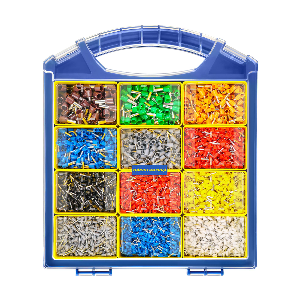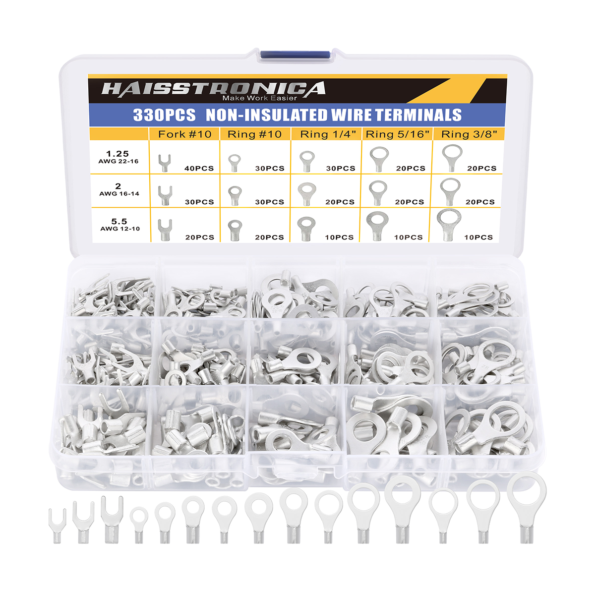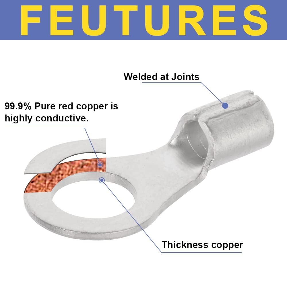

A full tool cycle is not the same as a verified crimp.
A crimp describes a formed connection. A full-cycle ratchet describes how a tool completes its stroke. The connection still needs the right terminal, conductor, die, and inspection.
1. What does “full crimp” actually mean?
Crimping permanently deforms a terminal's metal barrel around a prepared conductor. The goal is reliable electrical contact and mechanical retention—not simply a visible dent or the hardest possible squeeze. Where provided, an insulation support is formed separately from the conductor crimp.
“Full crimp” is often informal shorthand for a completed connection. It is not, by itself, a universal crimp shape, test result, or certification. Separate these three ideas:
Partial compression: a process stopped short
The intended forming operation is unfinished. A wire may feel captured while the barrel has not reached its specified shape or dimensions. Do not accept it merely because it survives a light tug.
A single indentation: a shape, not a verdict
An indent can be the intended profile for a compatible lug or terminal. One visible impression does not automatically mean “partial.” Follow the specified profile, location, and number of crimps; an improvised dent from pliers is not an equivalent process.
Profile reference: Klauke's indent-crimp explanation.
A full ratchet cycle: a completed tool stroke
The ratchet normally holds the handles through the forming stroke, then releases at the designed endpoint. This helps prevent stopping early. It does not identify the terminal, check insertion depth, or prove the finished joint meets its specification.
Complete does not mean crushed flat. More pressure is not automatically better. The correct finished geometry depends on the terminal system. A completed crimp also does not make an unsealed connector waterproof.
2. Self-test: does your tool release midway?
Disconnect power and use a compatible sample terminal and wire. Keep fingers clear of the jaws. Follow the tool's inspection procedure; do not force a jammed tool or modify its ratchet.
-
1
Identify normal release versus emergency release.
A deliberate release lever may open a ratchet mid-cycle. That safety feature is not a fault. -
2
Observe the normal closing stroke.
If a full-cycle tool releases prematurely without the release lever, stop and inspect it according to its instructions. -
3
Check the sample after the cycle.
Correct release behavior is only one check. Continue with die matching and joint inspection below.
Mechanism reference: TE Connectivity's full-cycle ratchet and emergency-release description.
No ratchet does not automatically mean a bad tool. A suitable non-ratcheting tool can remain useful when its specified procedure produces verified results. A ratchet is worth considering when stopping short or inconsistent completion is the recurring problem.
Need cycle control for heat-shrink terminals?

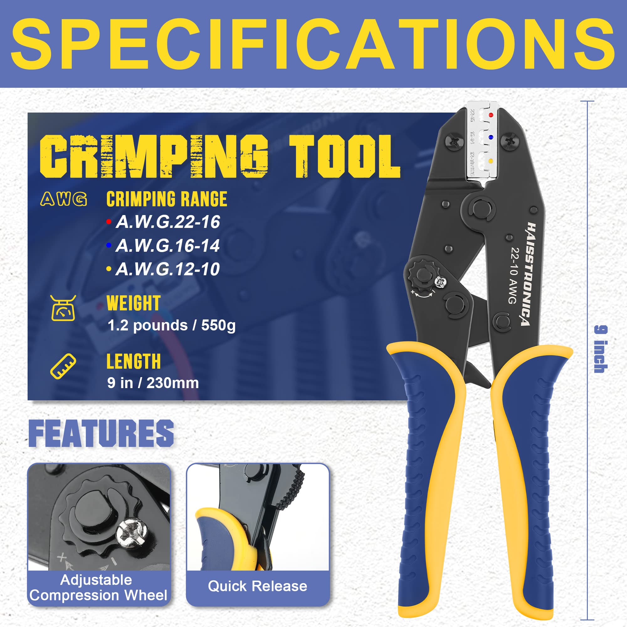
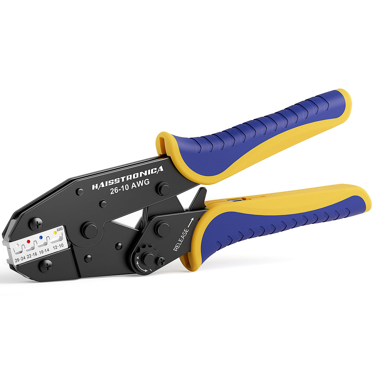
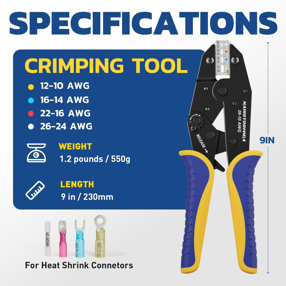
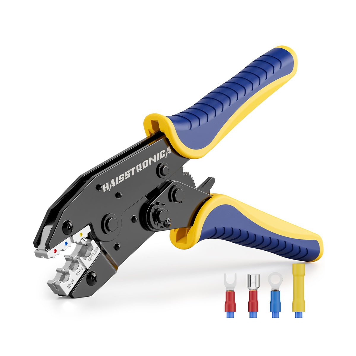
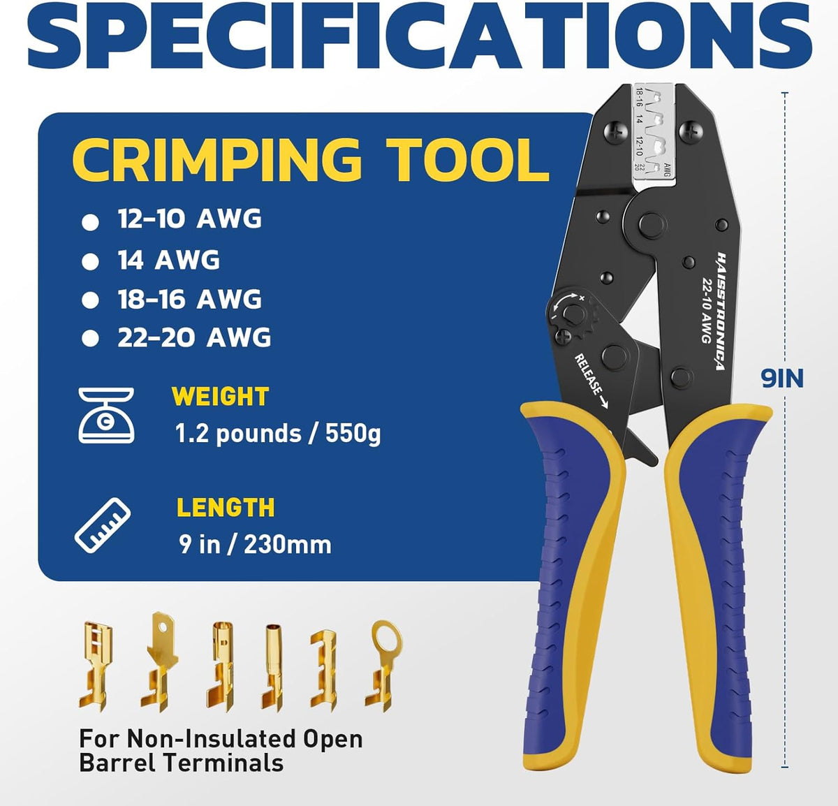
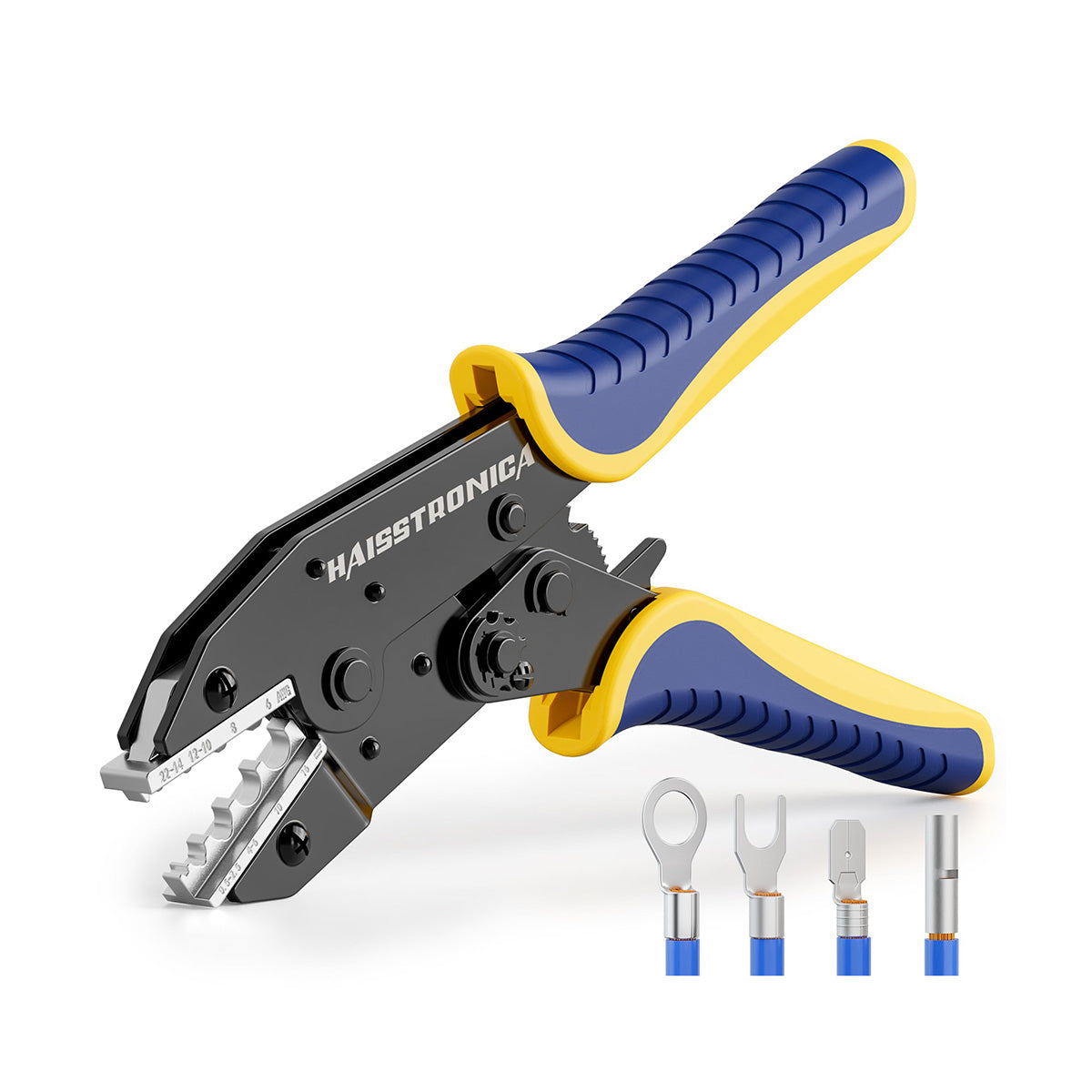
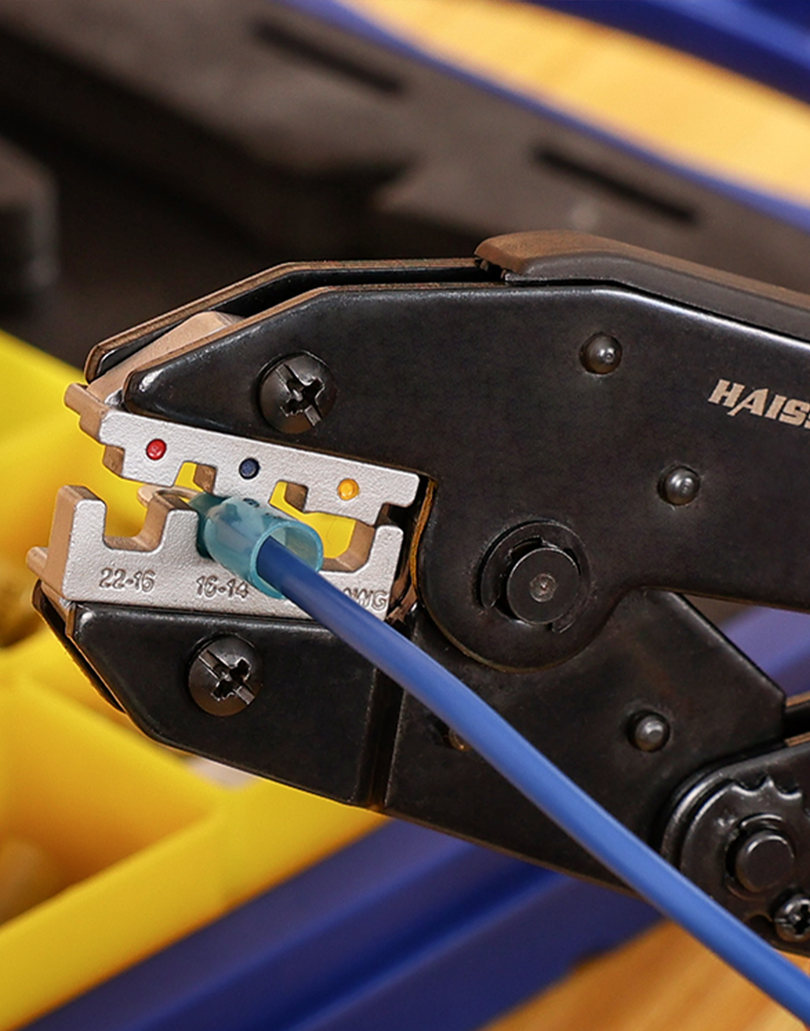
The AWG 22–10 Ratchet Crimping Tool uses a full-cycle mechanism and marked jaw positions for compatible heat-shrink terminals.
Choose it only when the terminal profile and conductor range match. It is not an open-barrel, ferrule, or heavy-lug substitute.
3. Match the connector shape before the tool
The barrel geometry selects the die; the conductor range selects the cavity. A shared AWG number does not make two crimp profiles interchangeable. Confirm the terminal part, wire construction, strip length, die markings, and required orientation before starting.
Open-barrel terminals: form the wings
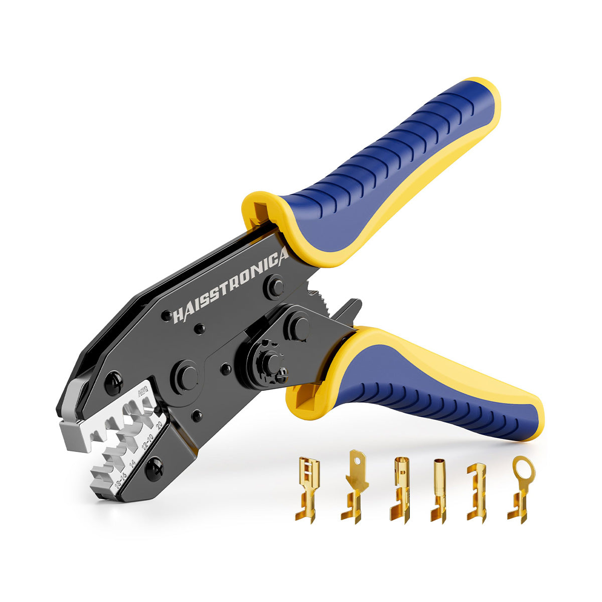
Use an open-barrel profile that forms the conductor wings and the intended insulation support.
This tool covers compatible terminals in its marked AWG 20–18, 18–14, and 12–10 positions. Do not assume it fits every small OEM pin.
Ferrules: compress the cable-end sleeve

A ferrule prepares a stranded conductor for a compatible terminal block; it is not a butt splice.
Use a dedicated ferrule die. Check the sleeve, conductor, and terminal-block requirements against this tool’s AWG 24–8 range.
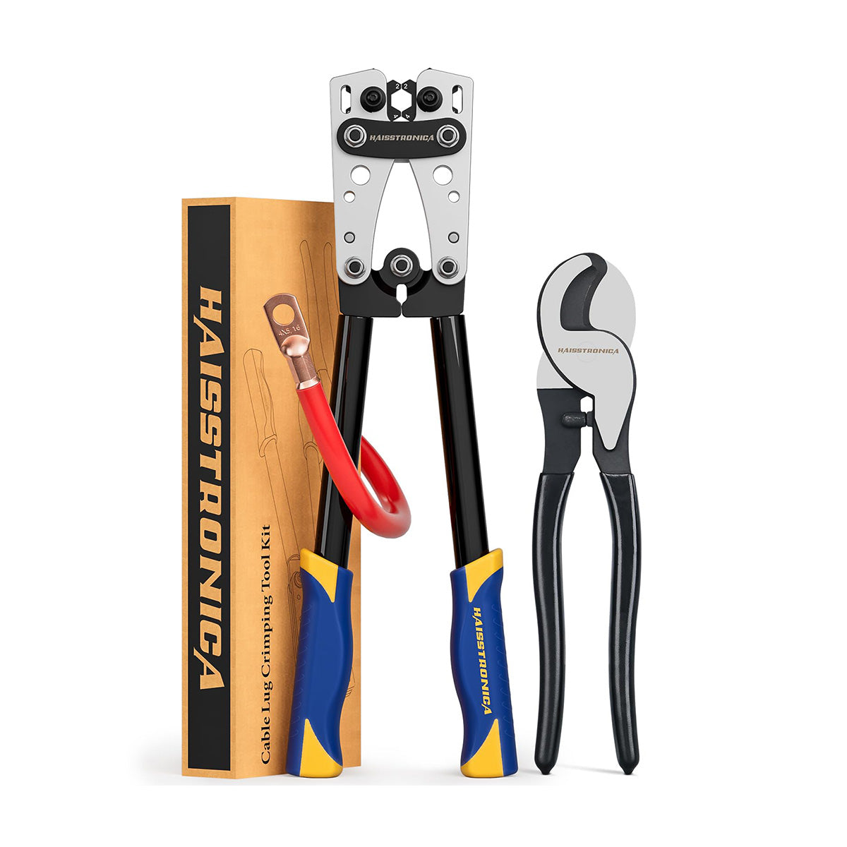
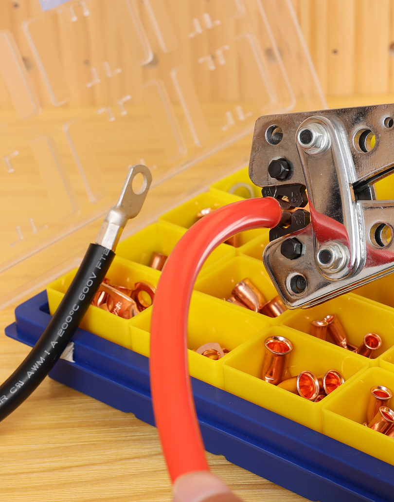
Closed-barrel non-insulated terminals or heavy cable lugs? Use the terminal manufacturer's specified profile and capacity. A small heat-shrink-terminal die is not a shortcut for a large battery lug. If your connector does not fit one of the routes above, compare the connector-specific crimpers before choosing.
Several terminal families on the same bench?
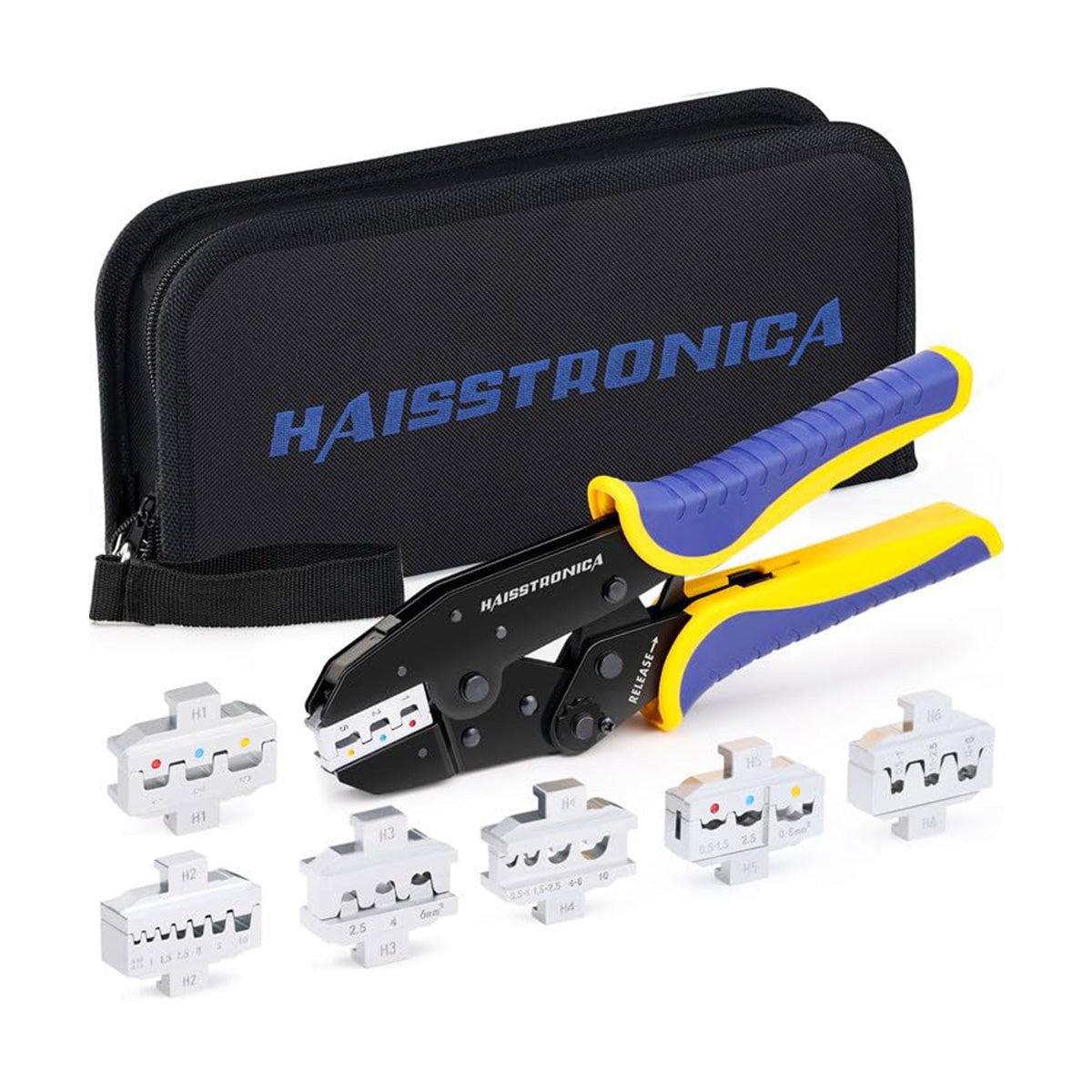
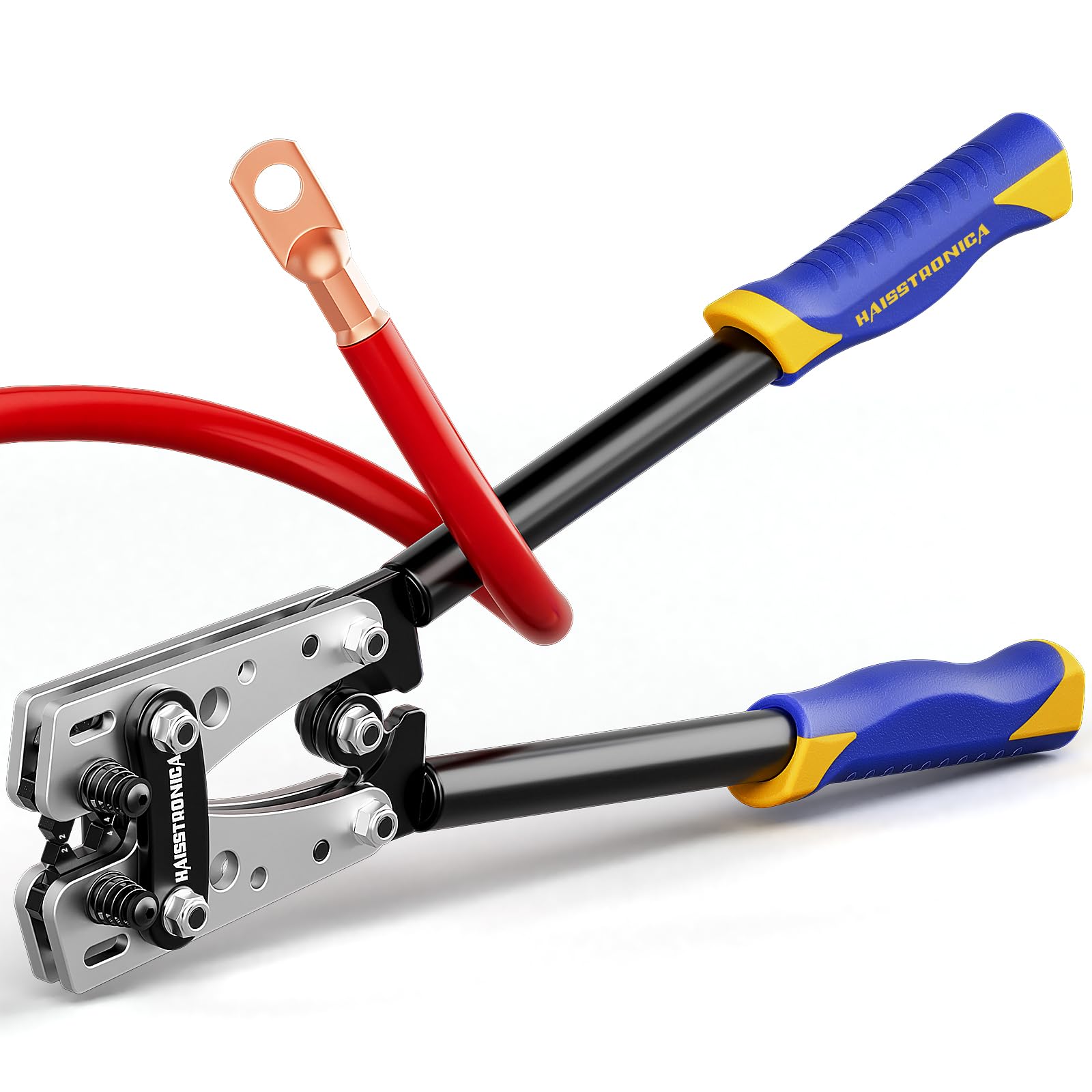
The 6-in-1 Ratcheting Crimper with 6 Interchangeable Dies lets one frame serve several supported connector families.
Match each die to its own terminal type and printed range. Changing the die changes the application—not the need to verify the crimp. This version does not include a separate wire stripper.
4. Inspect the connection—not just the handle release
Use the acceptance requirements for the exact terminal, wire, and tooling combination. There is no single crimp height or pull-force value that applies to every connector.
Look: conductor, barrel, and support
Check insertion and strip length, escaped or damaged strands, barrel cracks, and the required insulation support. Compare the result with the terminal's approved example—not an unrelated connector photo.
Measure: use the specified dimensions
Where the terminal specification calls for crimp height or other dimensions, measure at the specified location with the appropriate gauge. Do not adjust pressure by appearance alone.
Test: distinguish screening from validation
A gentle hand check can reveal an obviously loose wire; it is not a calibrated pull-force test. Formal pull testing uses the specified method, force, and representative samples. Destructively tested samples are not installed.
Example manufacturer requirements: Molex terminal-specific crimp dimensions and sample pull testing (PDF). Its values apply only to the listed combination.
If a sample fails, stop and find the cause. Recheck size, die, preparation, positioning, and tool condition. Do not keep squeezing the same damaged terminal or tighten the adjustment wheel to compensate for a mismatched die. Replace rejected terminals and validate fresh samples.
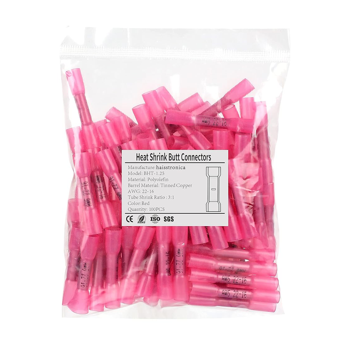
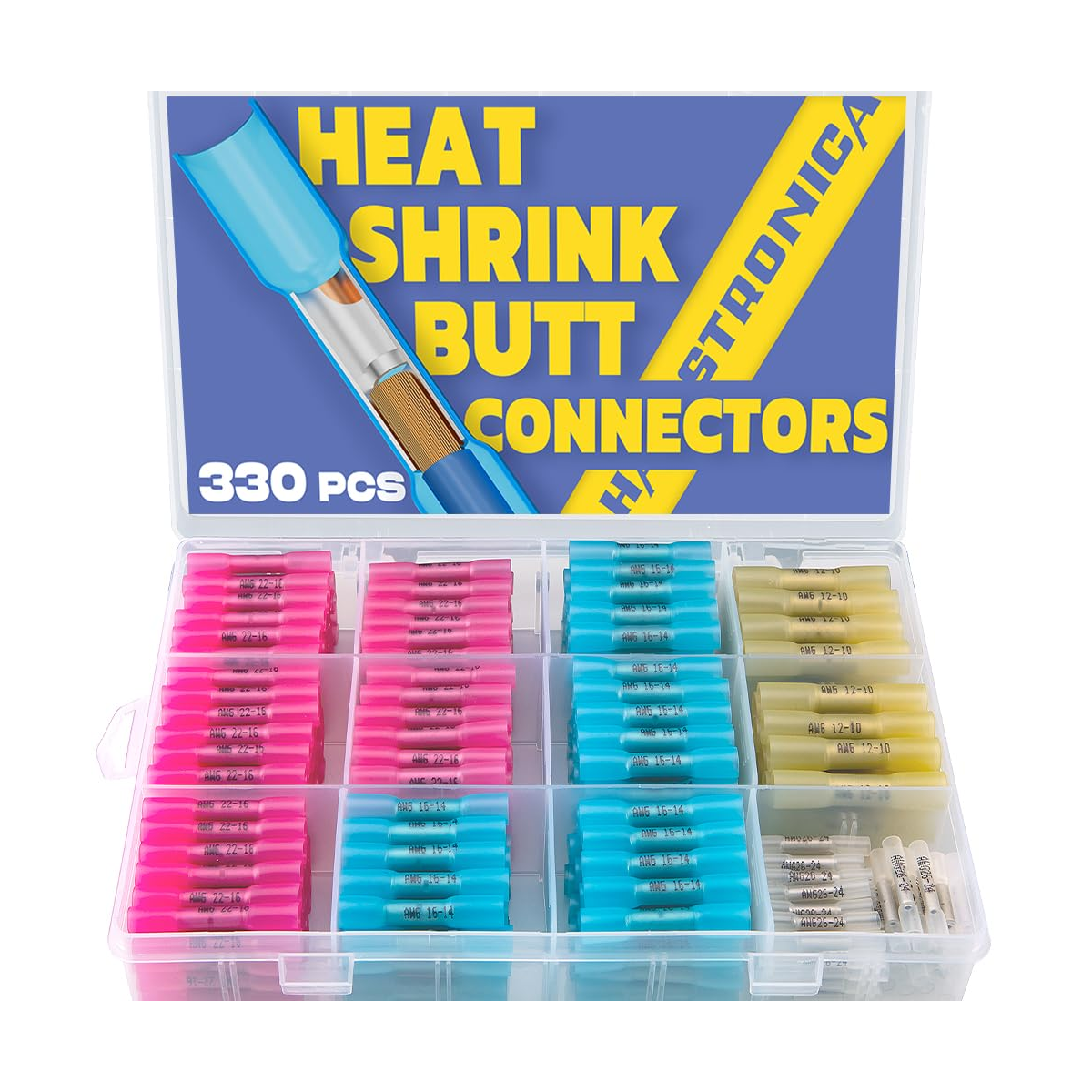
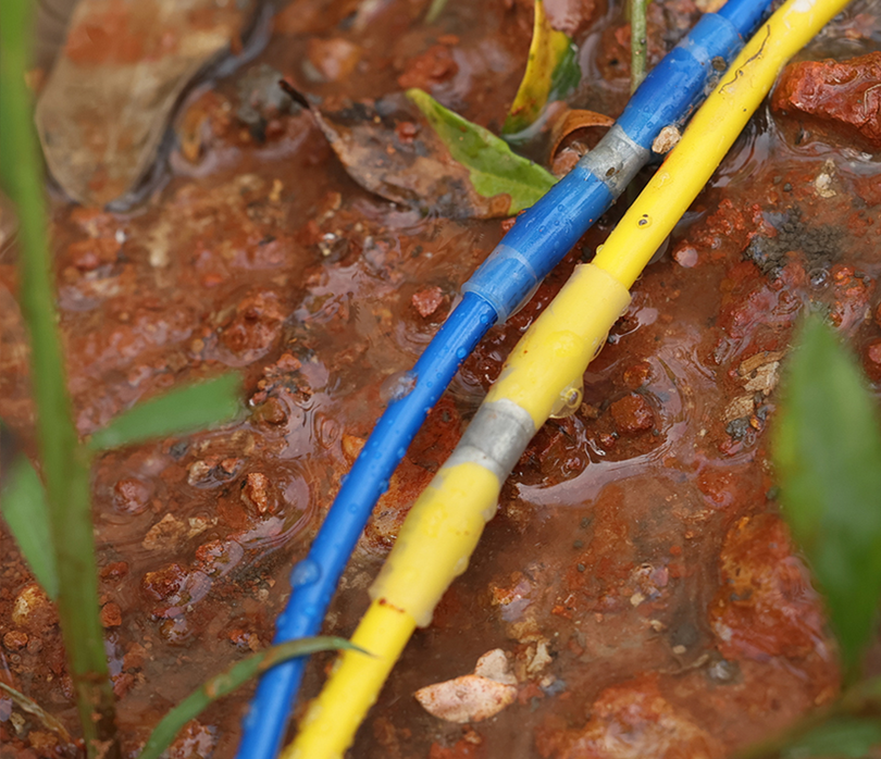
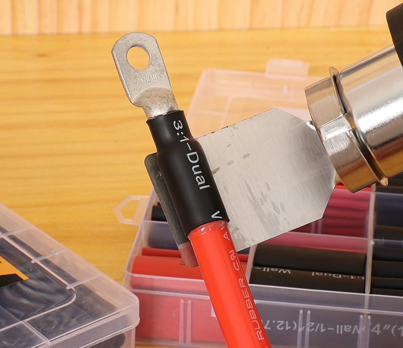
For heat-shrink terminals: make and inspect the mechanical crimp before applying the connector's specified sealing procedure. Provide the required support and environmental protection.
5. Keep your current tool—or upgrade for a clear reason
Your existing tool is suitable
Keep it when the die and range match, the mechanism works as specified, the jaws are sound, and sample connections pass the required checks.
Build a repeatable setup: record the terminal, wire, die, and inspection method. Buying a new handle will not fix incorrect preparation.
Use the Inspection Checklist ↑You have a reason to upgrade
Consider a full-cycle ratchet for repeated incomplete strokes; a dedicated crimper for a different connector geometry; or the 6-in-1 kit for several supported terminal families.
Service or replace worn tooling according to its instructions. Do not use a damaged tool while waiting for an upgrade.
Match the Tool to the Connector ↑Upgrade the missing capability—not just the tool.
Need cycle control, a different die, or several compatible profiles? Choose that capability first. If your current setup already meets the terminal requirements, keep using it and maintain your checks.
Compare Wire Crimpers by Connector Type →Quick answers
Does “full crimp” mean squeezing twice?
No. Follow the terminal's specified crimp locations and sequence. Some terminals require multiple operations; extra squeezes are not a universal quality improvement.
Can a ratchet crimper still make a bad connection?
Yes. The wrong die, incorrect wire range, poor stripping, or incomplete insertion can produce a rejected joint even after a completed cycle.
Is a visible indent a sign of failure?
Not by itself. An indent may be the correct profile for a compatible terminal. Judge it against that terminal's tooling and inspection requirements.