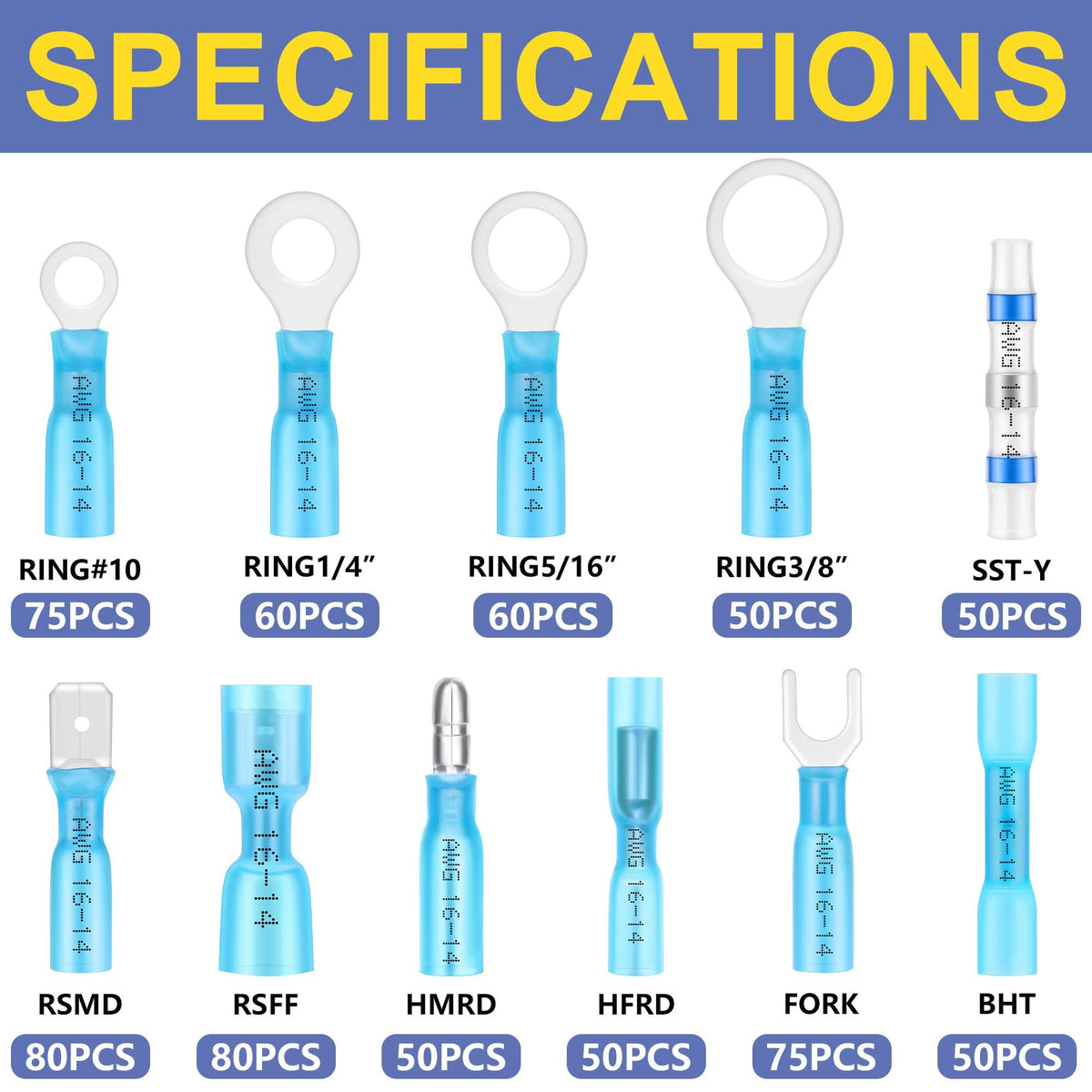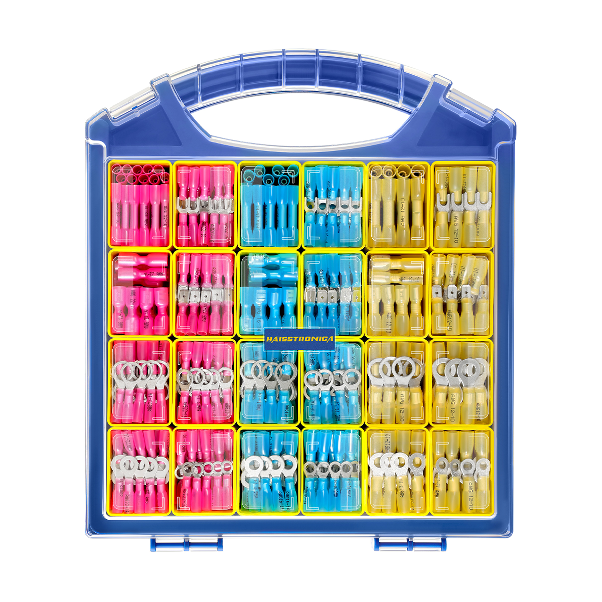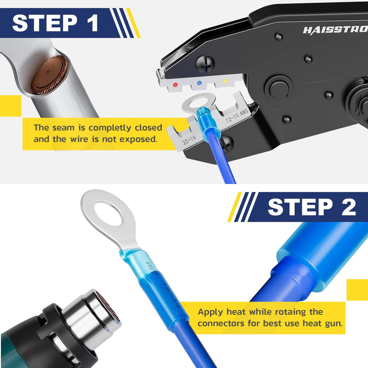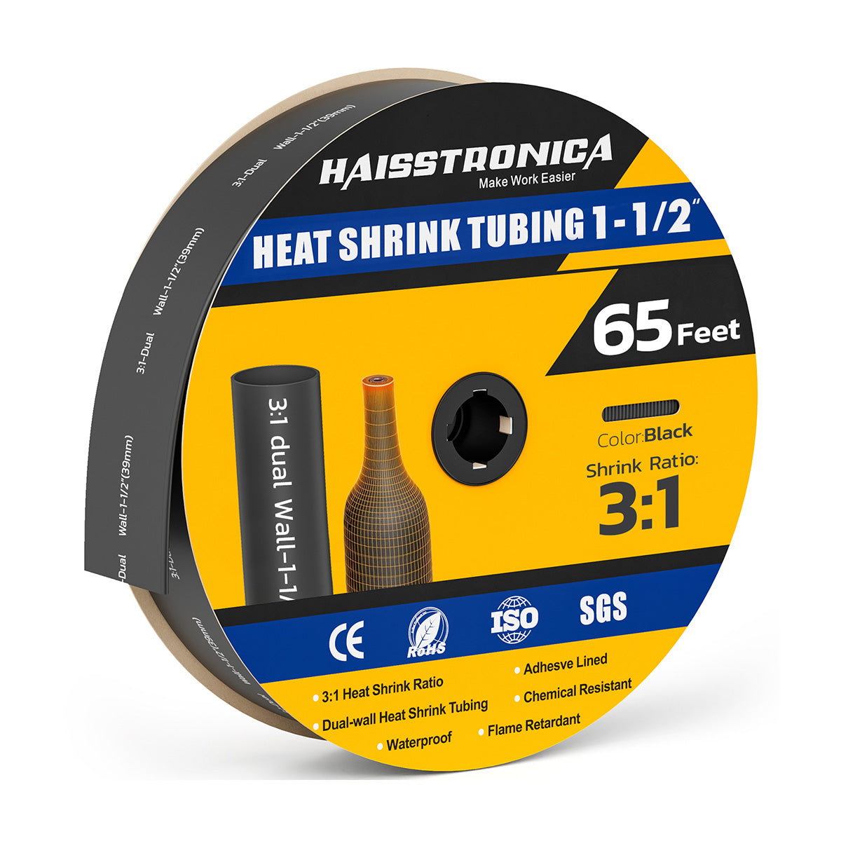

First question: do you need to connect two wires?
Heat-shrink tubing and solder-seal connectors can both insulate and seal, but they do different jobs. Choose by the electrical task first—then by environment, tooling, and size.
Does this job require a new electrical splice?
Protect an existing connection
Use heat-shrink tubing to insulate, reinforce, bundle, or seal a connection that already has its own electrical joint.
Browse Heat Shrink Tubing →Connect and seal two wires
Where the project permits a soldered inline splice, a correctly sized solder-seal sleeve can form and seal the joint with controlled heat.
Browse Solder Seal Connectors →What each product actually does
Covers; it does not create conductivity
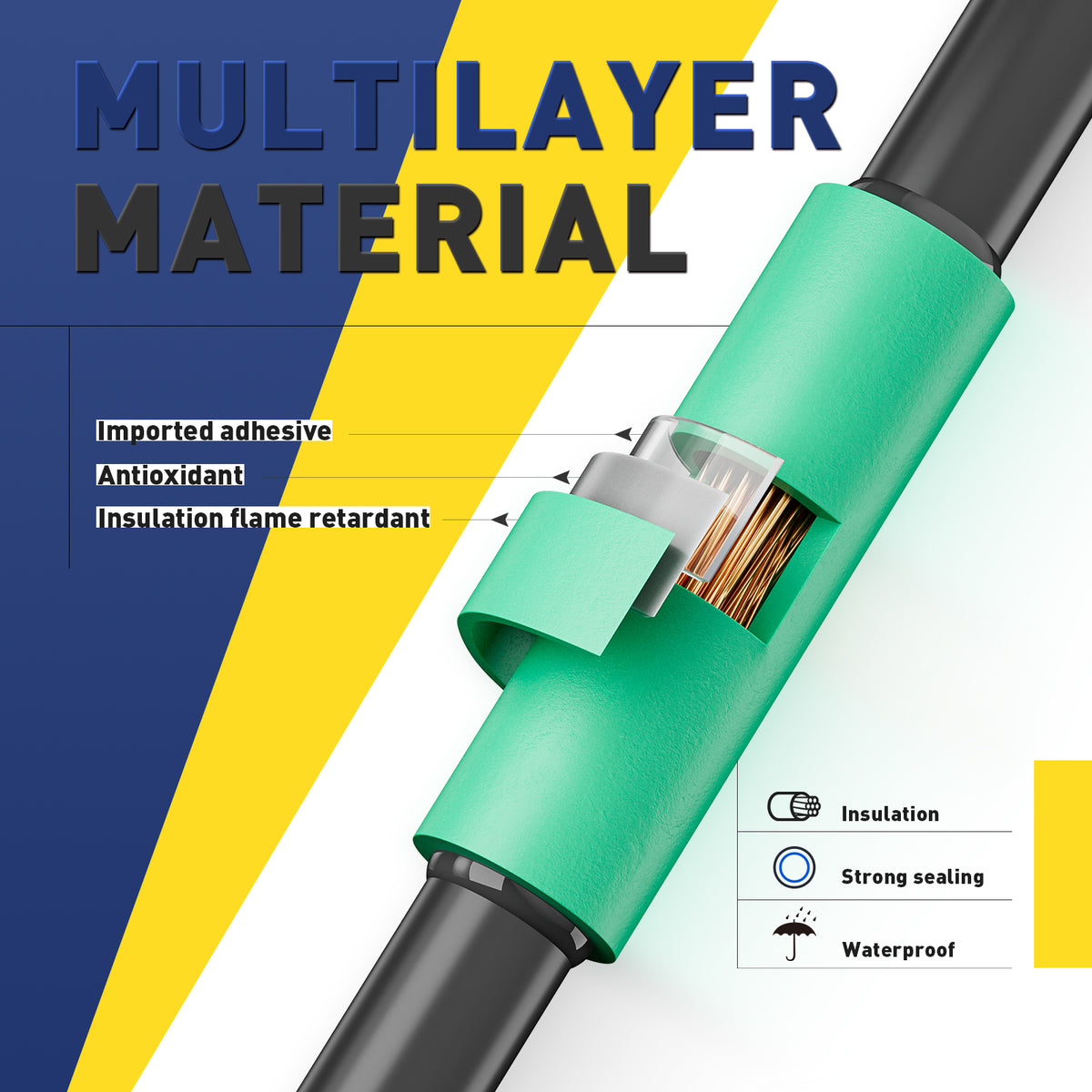
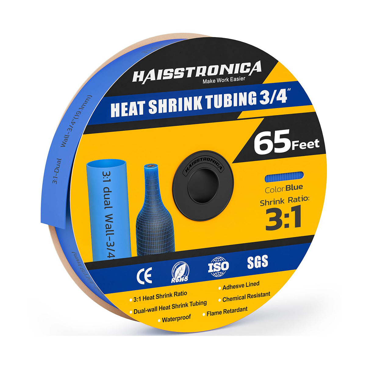
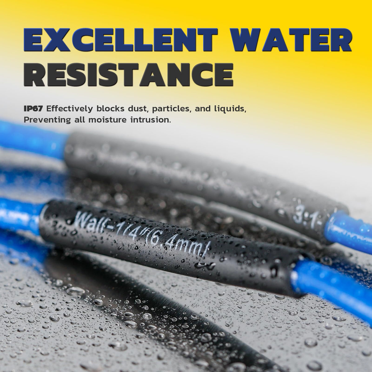
Tubing shrinks around an existing splice, terminal, soldered joint, crimp barrel, or cable section. It adds insulation, abrasion protection, strain transition, identification, or adhesive sealing.
Shop Tubing Collection →Creates and seals an inline splice
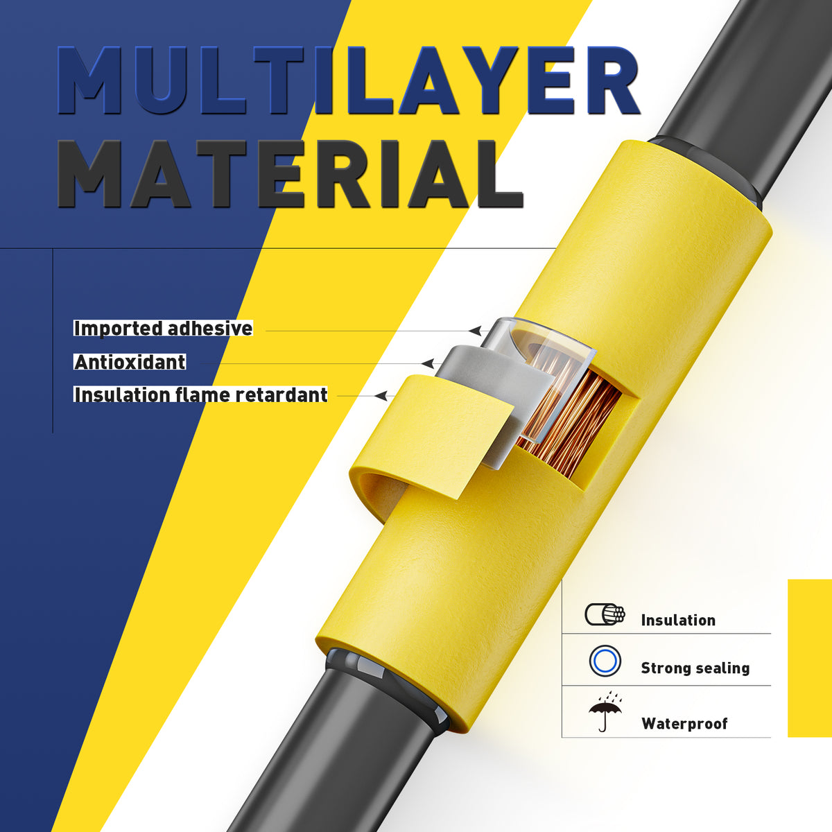
The sleeve contains a solder ring and sealing rings. With correct conductor overlap and controlled heat, the solder flows through the strands while the sleeve shrinks and seals.
Shop Solder Seal Collection →The practical comparison
| Decision factor | Heat-shrink tubing | Solder-seal connector |
|---|---|---|
| Electrical connection | None. The joint must already be mechanically and electrically complete. | The solder ring forms the inline electrical splice when fully melted and wetted through the conductor strands. |
| Main purpose | Insulation, protection, bundling, abrasion resistance, labeling, and optional adhesive sealing. | Join two compatible wires and provide insulation plus sealing in one sleeve. |
| Preparation | Slide tubing into position before the terminal or splice blocks access; center it over the finished joint. | Strip both wires, overlap or insert them as specified, and center the solder ring over the conductors. |
| Heat requirement | Enough controlled heat to fully recover the tubing without damaging nearby insulation. | Enough controlled heat to shrink the sleeve, activate seals, and visibly melt the solder through the strands. |
| Rework | Usually cut off and replaced; the underlying joint may remain intact. | Normally cut out with the splice and remade because the solder ring becomes part of the joint. |
| Best route | Browse Tubing → | Browse Solder Seal → |
Choose by project scenario
| Project | Recommended direction | Product route |
|---|---|---|
| Protect a finished crimp or solder joint | Use correctly sized tubing. Choose adhesive-lined tubing if compatible moisture sealing is required. | Heat Shrink Tubing → |
| Repair worn insulation or add abrasion protection | Use tubing only when the conductor itself is undamaged and the repair method is permitted. | Tubing Collection → |
| Create a compact inline low-current splice | Where solder-seal use is permitted, choose the connector by conductor range and apply slow, even heat. | Solder Seal Collection → |
| High vibration, high current, high heat, or critical circuit | Do not choose solely between these two. Follow the specified mechanical terminal, connector, tooling, support, and inspection method. | Use the equipment-approved method |
Heat-shrink tubing sizing
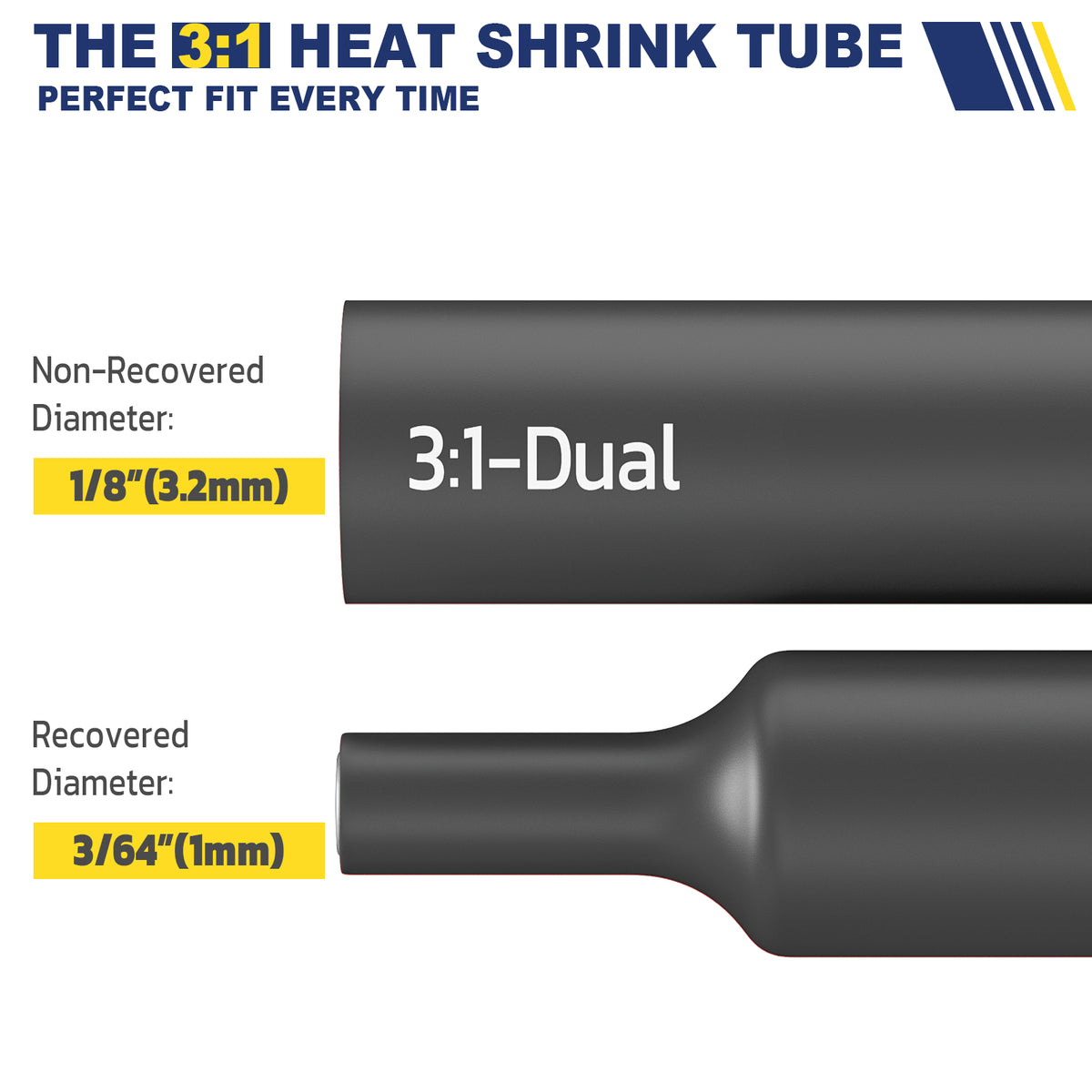
Measure the largest point the tubing must pass over and the smallest section it must seal around. The expanded tubing must slide into position; the fully recovered tubing must grip the final diameter.
Choose the expanded diameter
- Larger than the terminal, splice, or connector it must pass over.
- Allow enough clearance for easy positioning without forcing.
- Place the tubing on the wire before completing a joint that blocks access.
Check the recovered diameter
- Small enough to grip the cable or insulation after shrinking.
- Use adhesive-lined tubing when the application calls for environmental sealing.
- Do not assume a high shrink ratio corrects a poor size choice.
| Tubing type | Typical selection logic | Next step |
|---|---|---|
| 2:1 tubing | Useful when the largest and smallest diameters are relatively close and a straightforward insulation cover is needed. | Compare 2:1 Options → |
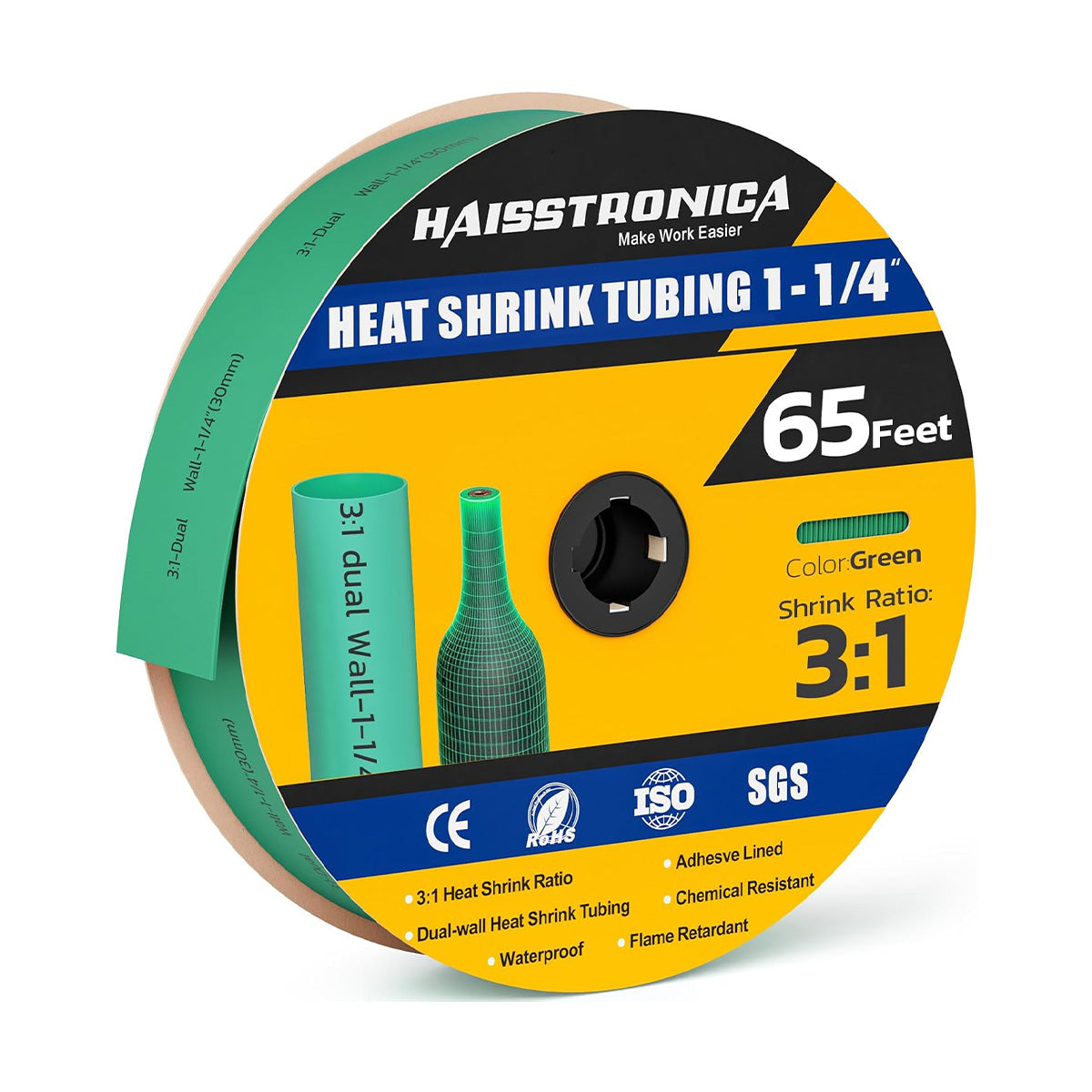
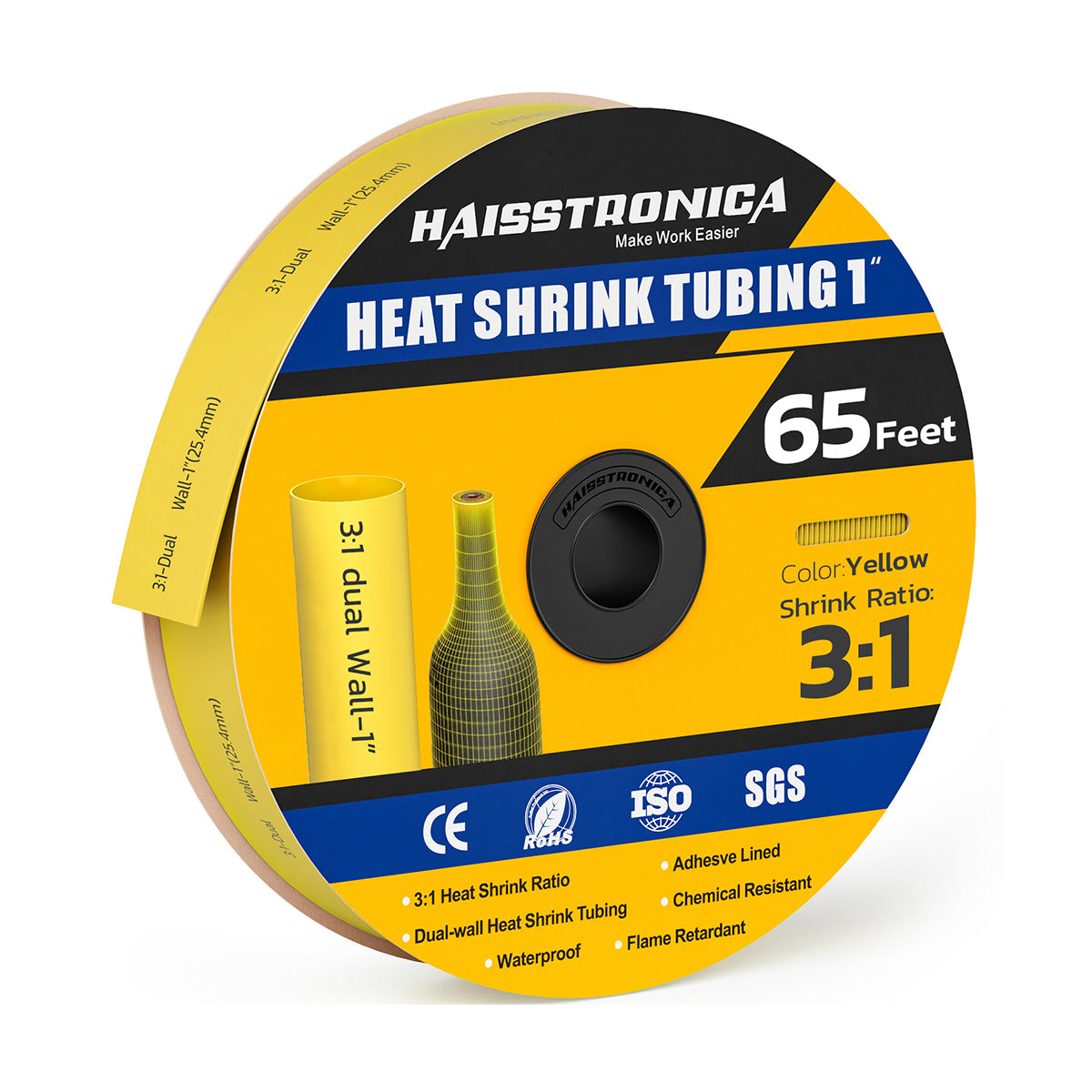
| 3:1 tubing | Provides more recovery range for connectors or diameter changes; adhesive-lined versions can add sealing. | Compare 3:1 Options → |
| 4:1 / heavy recovery | Consider for larger transitions only when wall thickness, recovered diameter, temperature, and application remain compatible. | Browse Tubing Collection → |
Solder-seal connector sizing
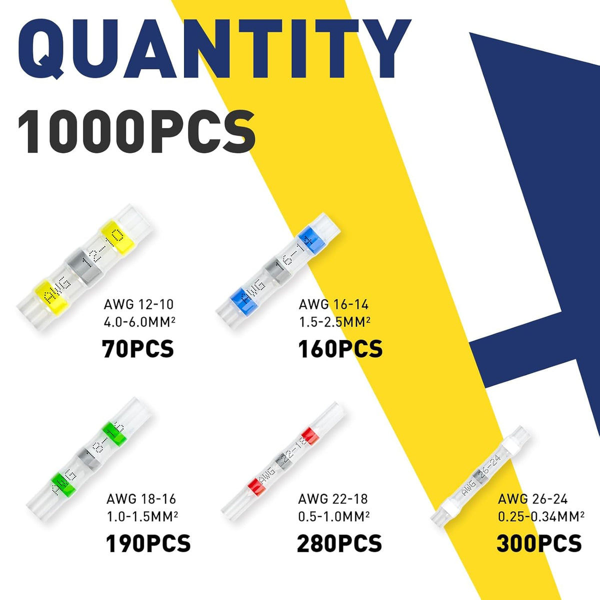
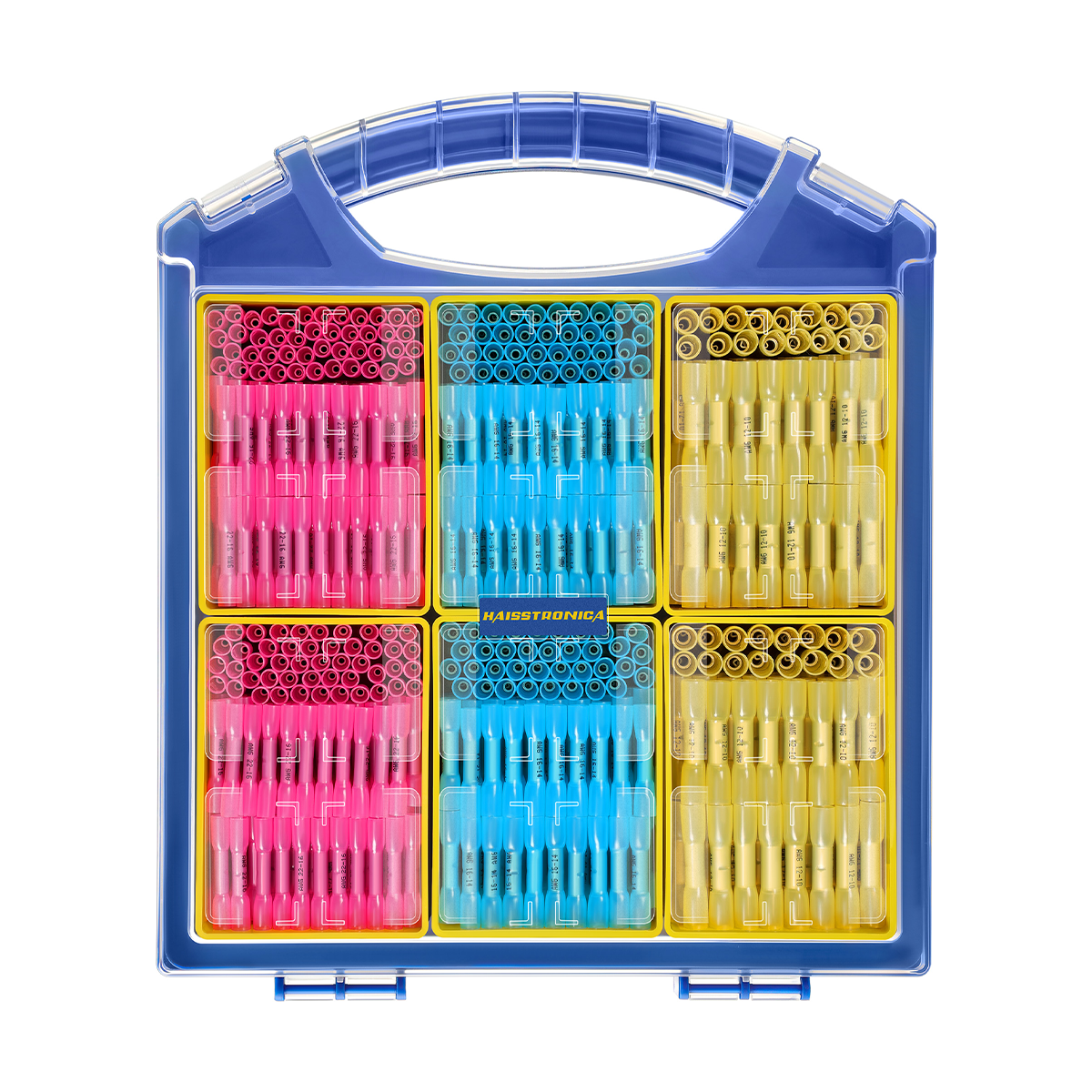
Use the printed connector range and the manufacturer's specification. Color is a fast reference, but wire construction and actual conductor size still matter.
| Common color | Typical wire range | Selection check | Route |
|---|---|---|---|
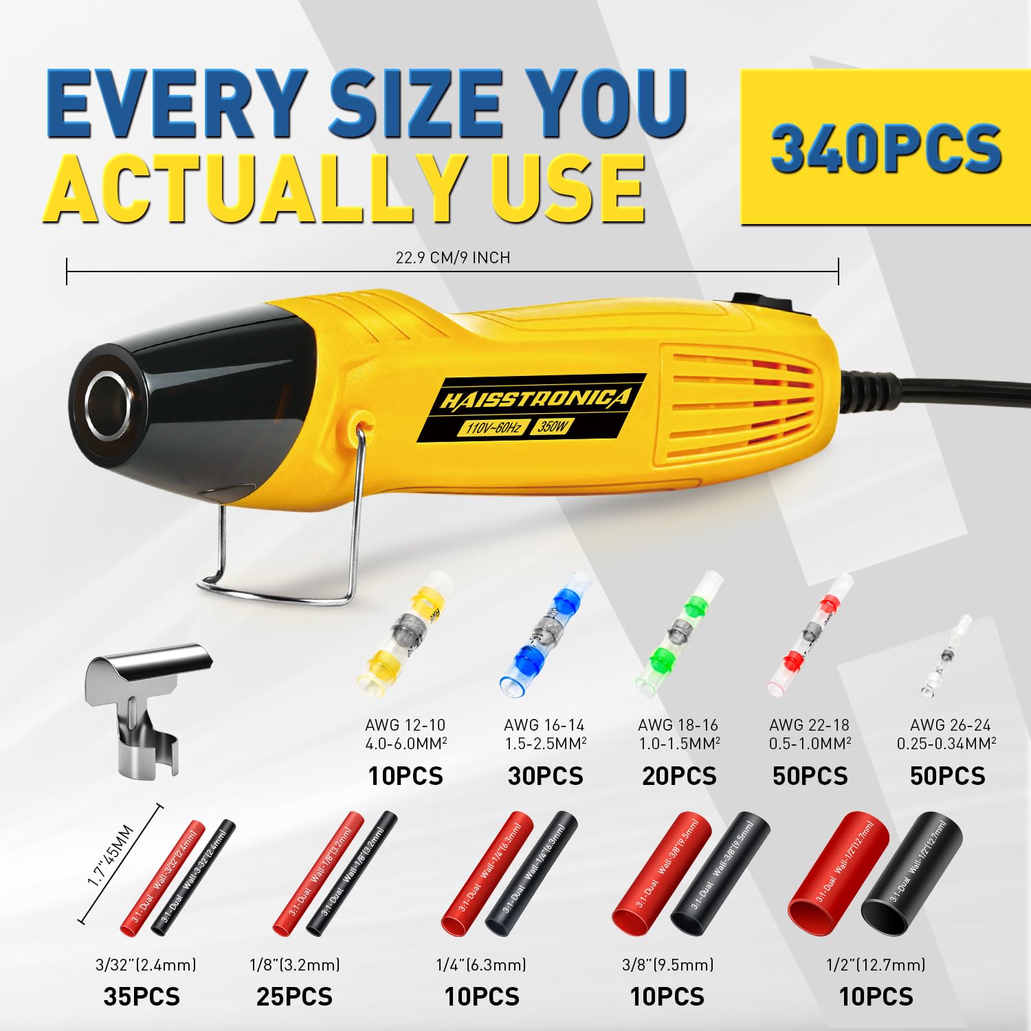
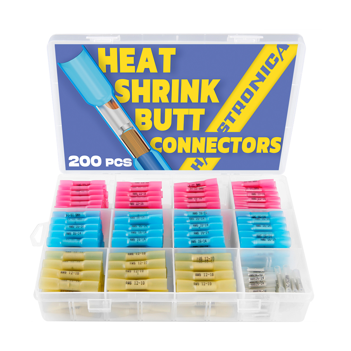
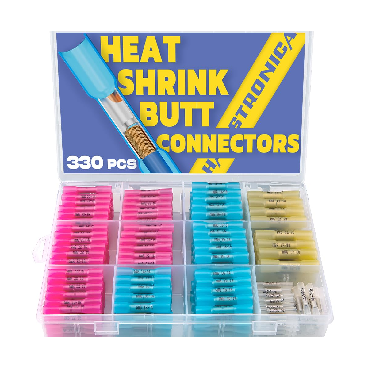
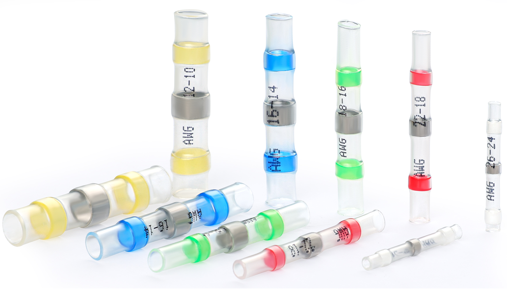
| White | AWG 26–24 | Confirm fine-wire compatibility and full strand overlap under the solder ring. | Shop → |
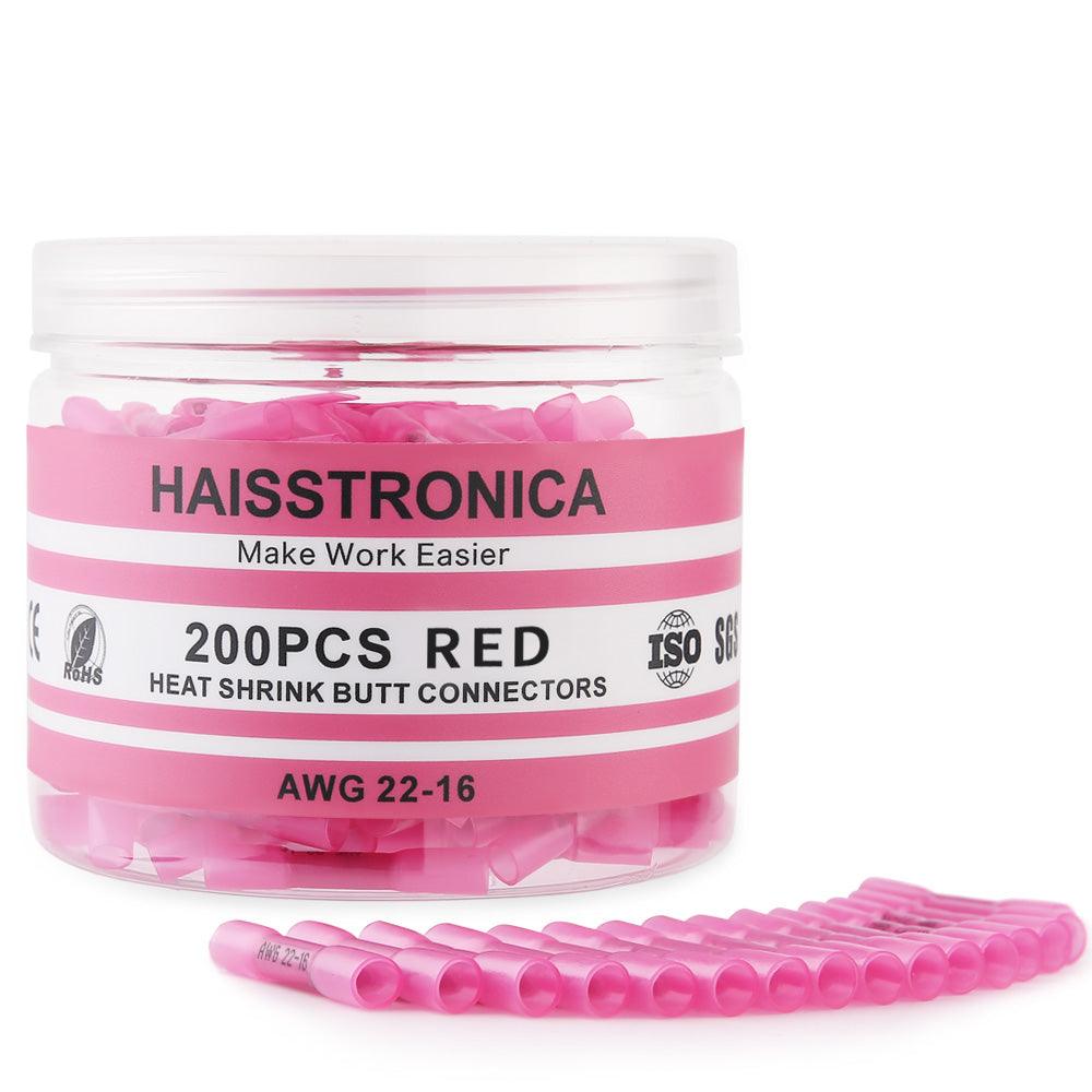
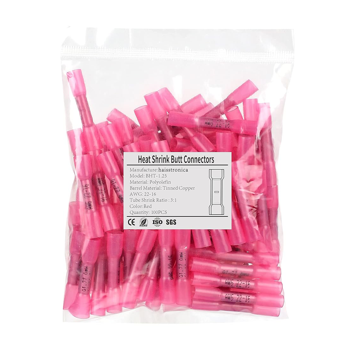
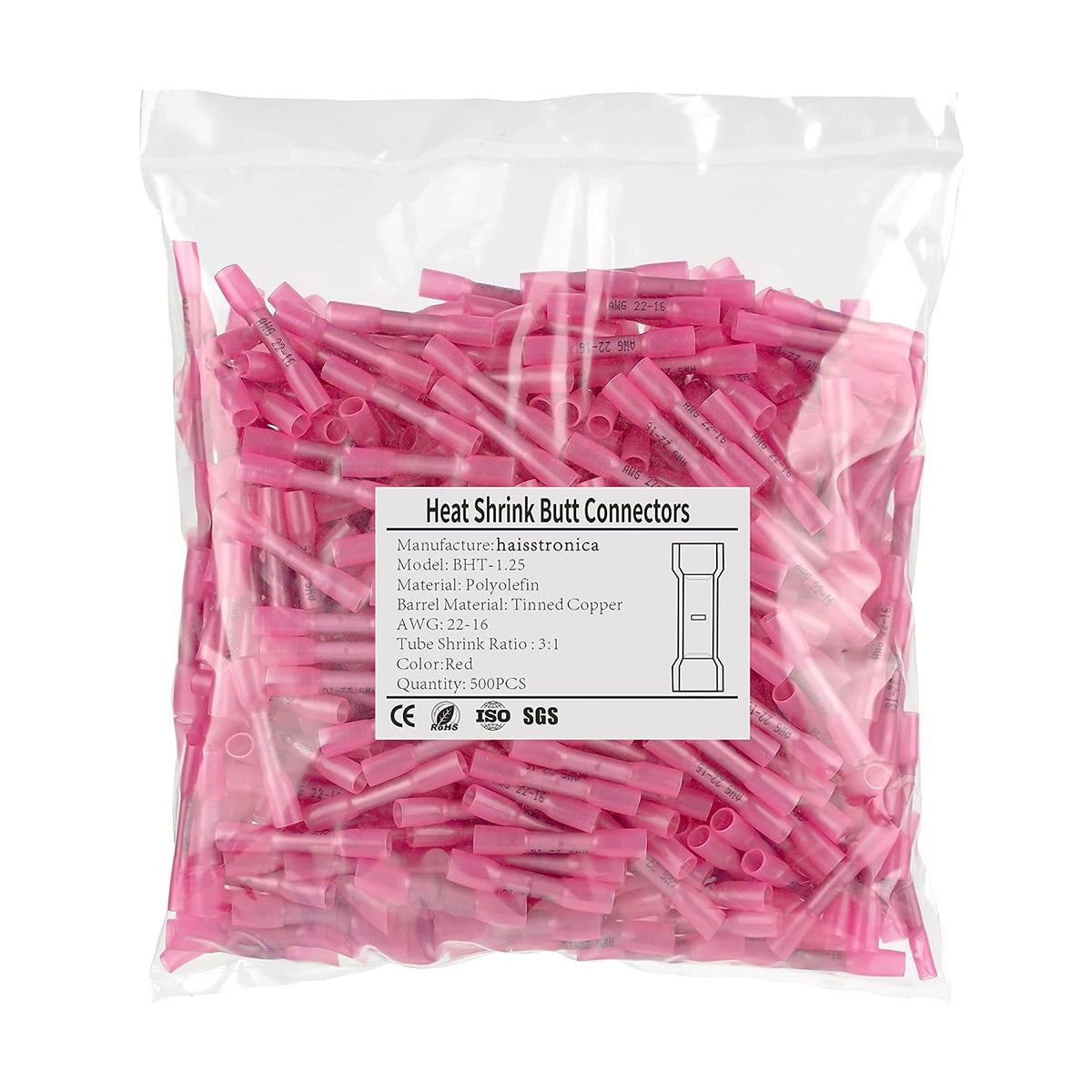
| Red | AWG 22–16 | The conductors should fit without bunching and remain centered during heating. | Shop → |
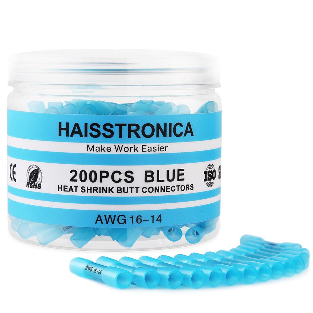
| Blue | AWG 16–14 | Verify conductor size, overlap, sleeve recovery, and intended circuit load. | Shop → |
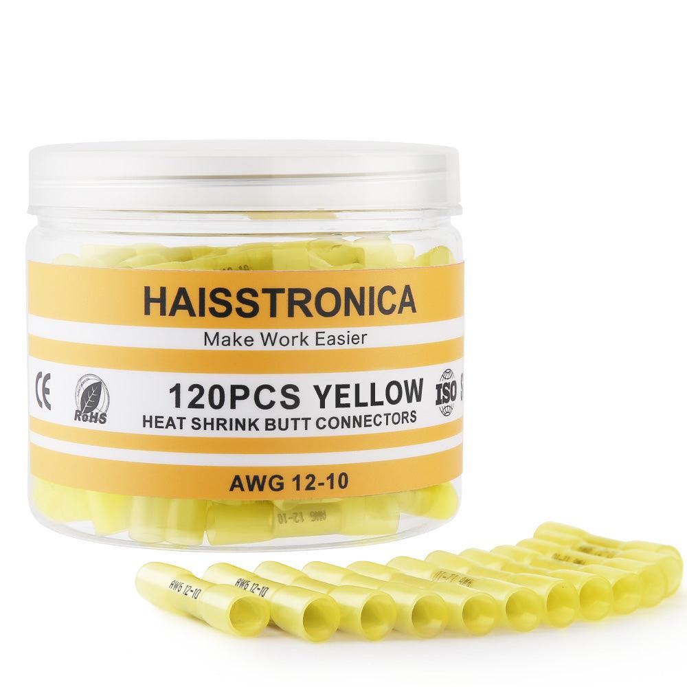
| Yellow | AWG 12–10 | Confirm the specific connector rating and whether solder seal is appropriate for the application. | Shop → |
Controlled heat is the common tool
Keep the heat moving
Rotate the work or move the heat source continuously. Start farther away and close the distance gradually. Stop if insulation discolors, bubbles, or scorches.
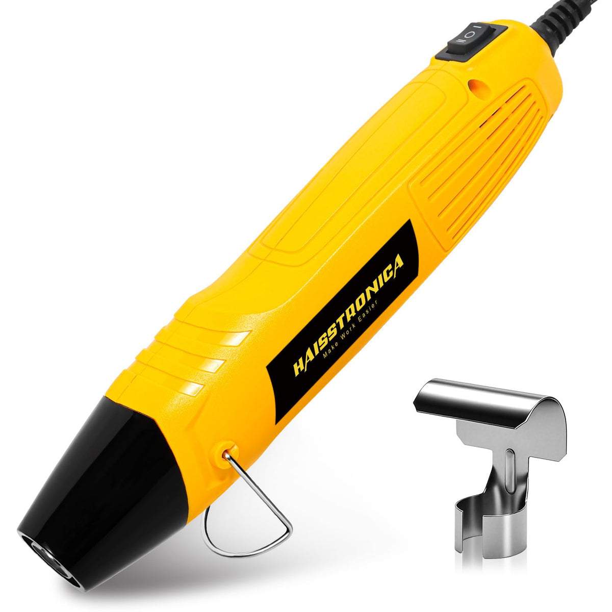
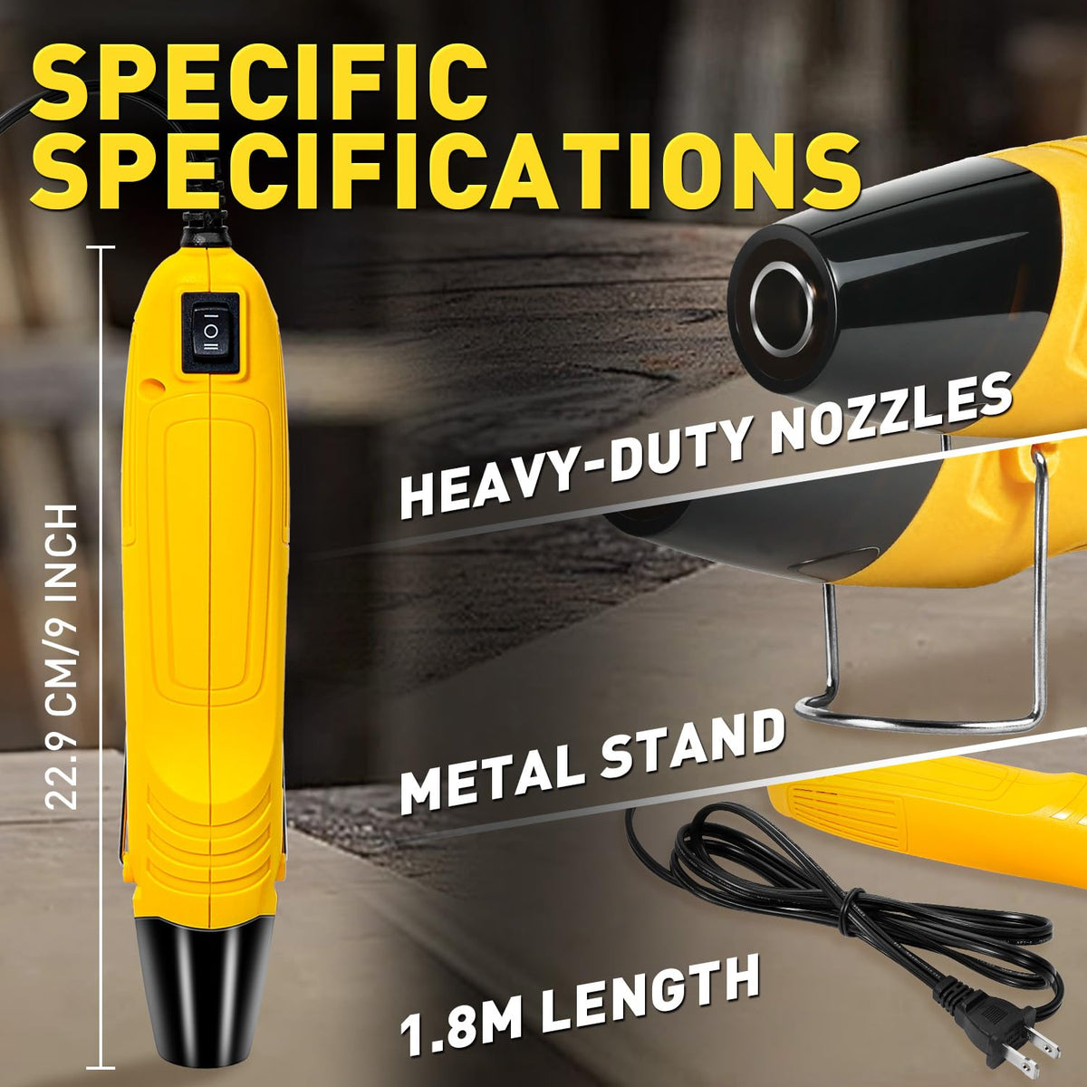
Shop Mini Heat Gun →Know what “complete” looks like
Tubing should recover evenly around the part. A solder-seal sleeve also requires visible solder flow through the strands—not simply a shrunken outer tube.
Choose Your Product Path ↓Application steps
Confirm the task
Protection only means tubing. A new inline splice may use solder seal only when the application permits it.
Measure before buying
For tubing, measure pass-over and final diameters. For solder seal, confirm conductor AWG and construction.
Prepare the wire
Clean the work area, preserve conductor strands, and position tubing before access is blocked.
Center the product
Center tubing over the finished joint or the solder ring over the conductor overlap.
Heat slowly and evenly
Use controlled heat, rotate the joint, and inspect all sides for complete recovery or solder flow.
Cool and inspect
Do not flex the joint while hot. Check sealing, insulation condition, conductor support, and application requirements.
Choose one matched buying path
Path A: protect an existing connection
Choose tubing by expanded diameter, recovered diameter, shrink ratio, wall type, and environment. Pair it with controlled heat—do not add solder-seal connectors unless the project also requires a new splice.

Heat Shrink Tubing Collection
Compare shrink ratios, sizes, colors, and adhesive-lined options.
Browse Tubing →
Heat Gun + Tubing Kit
A matched starter route for tubing selection and controlled shrinking.
Shop Tubing Kit →Path B: create and seal a new inline splice
Choose solder-seal connectors by conductor range and application. Pair them with controlled heat and correct wire preparation—do not add standalone tubing unless the finished repair specifically requires an additional permitted protective layer.
Solder Seal Connector Collection
Compare AWG ranges, pack sizes, and sealed inline splice options.
Browse Solder Seal →
Heat Gun + Solder Seal Kit
A matched route for building a new permitted inline splice with controlled heat.
Shop Solder Seal Kit →