
Apache Ranch Reviews · non-insulated splice kit
See the crimp before you seal it.
A bare butt connector and a separate 3:1 heat-shrink tube give you an inspection point between joining the wires and covering the joint. This review guide explains that workflow—and when a pre-insulated heat-shrink connector may be the simpler choice.
Two ways to build an insulated splice
Two connector types. Different installation steps.
Both need crimping and heat. The difference is whether you add a separate heat-shrink tube.
Reviewed approach · separate components
Bare connector: add a separate heat-shrink tube
The connector joins the wires. A separate tube covers the joint.
-
Slide the tube onto one wire
Before joining the wires, move the unheated tube away from the crimping area.
-
Crimp the connector, then inspect
Join both wires with the matched die. Leave the metal barrel uncovered for the required checks.
-
Cover the joint and heat the tube
Slide the tube over the checked crimp. Heat it as specified, then let it cool.
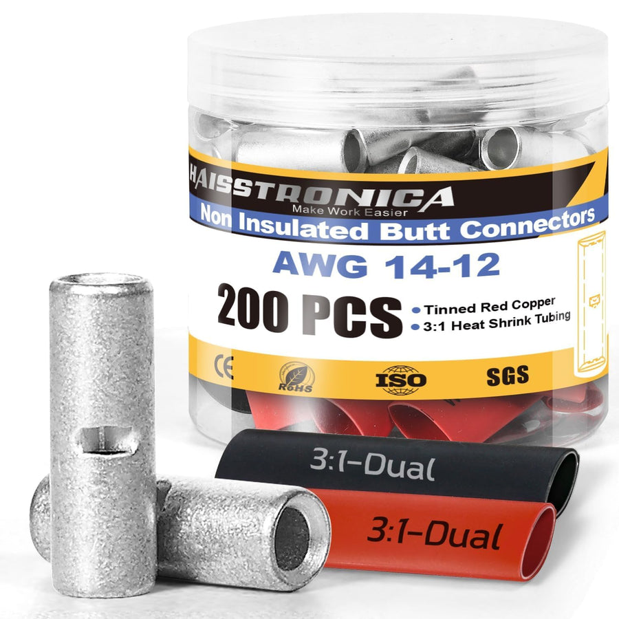
Tools sold separately.
Why choose it: inspect the exposed barrel and conductor entry points before positioning the tubing. You also control the sleeve's position and coverage within its specifications.
The trade-off: the tube is a separate part to size and position. Where it cannot be added afterward, slide it onto the wire before completing the splice.
Alternative · integrated sleeve
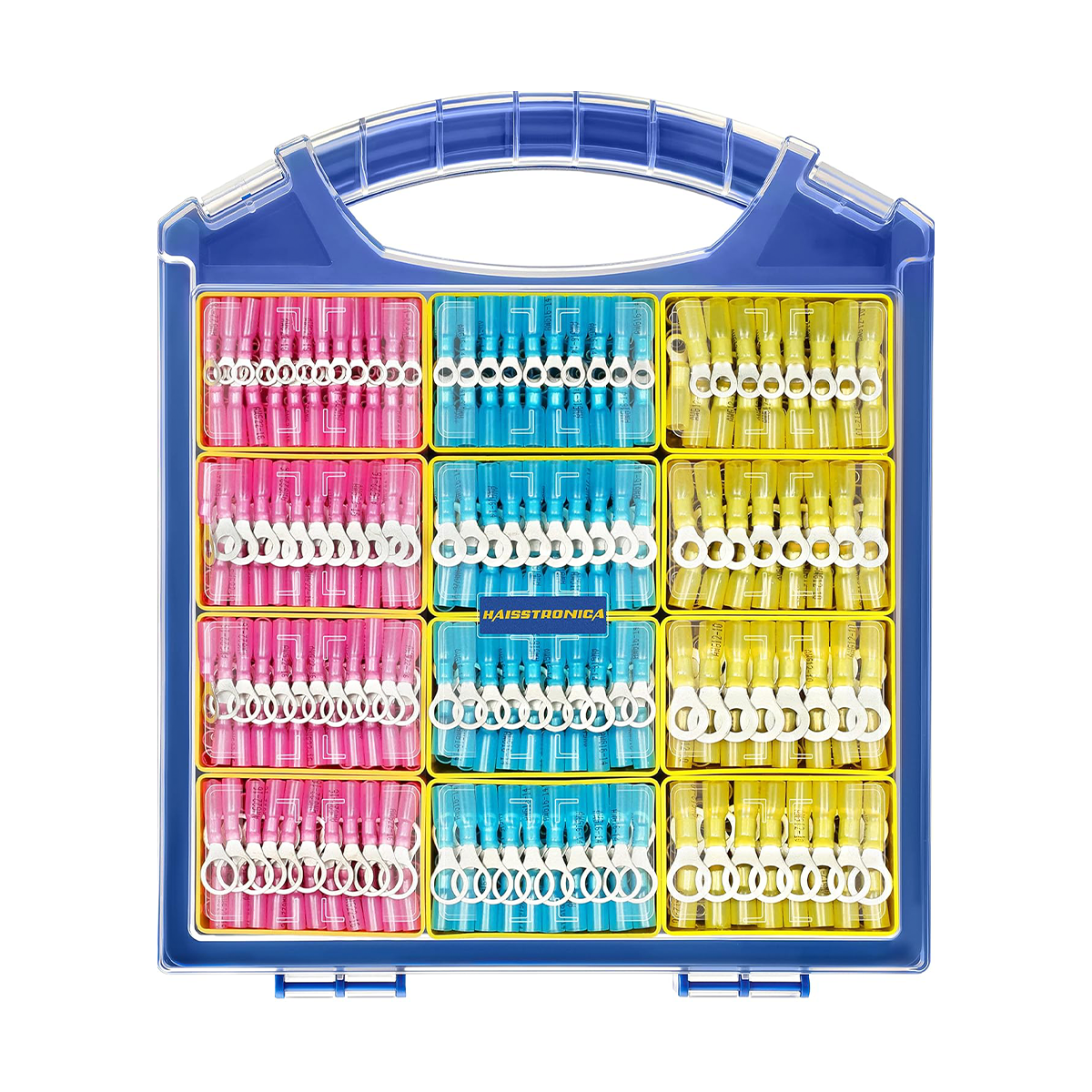
Heat-shrink connector: sleeve already fitted
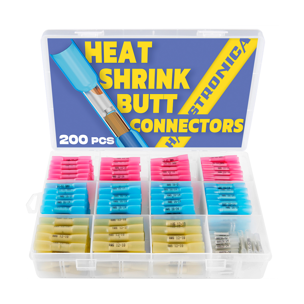
The connector comes with its heat-shrink sleeve already fitted.
-
Insert the stripped wires
Use the correct connector size and insert each wire to the specified depth.
-
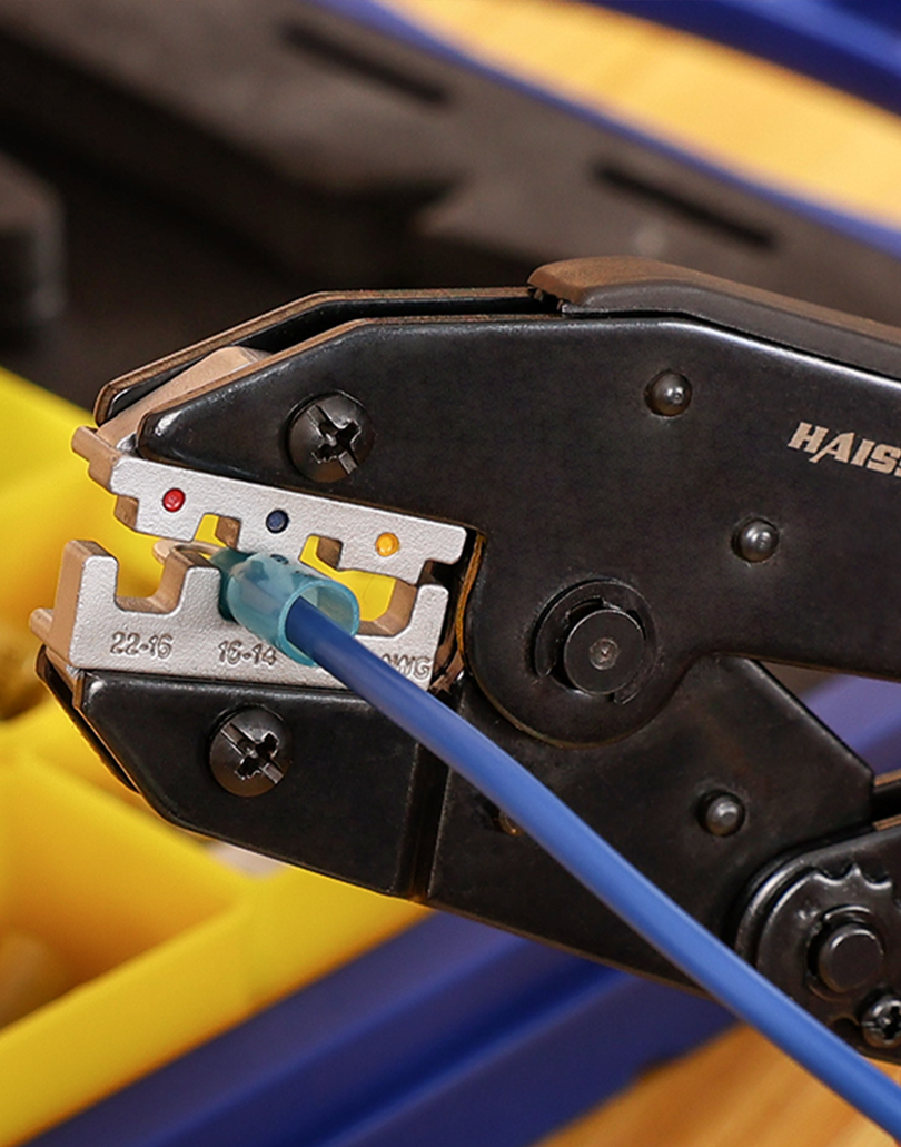
Crimp both ends with the matched tool
Use the specified heat-shrink-terminal die. Complete the required checks before heating.
-
Heat the outer sleeve, then let it cool
Use controlled hot air as instructed. Check the sleeve's recovery and seal without scorching the insulation.
The crimp joins the wires. Heat shrinks the insulating sleeve.
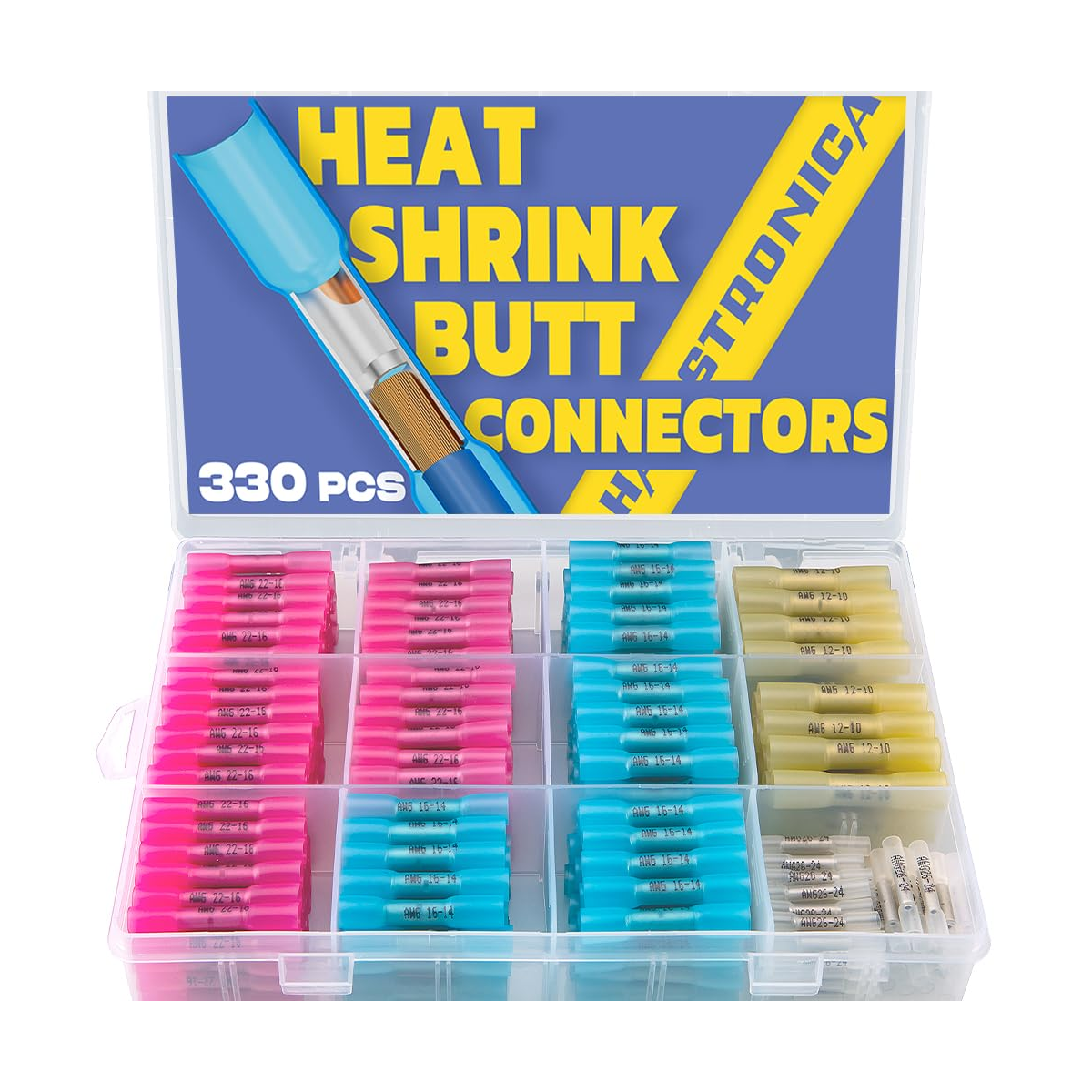
with built-in sleeves.
Why choose it: fewer loose components and no separate tube-positioning step. It can simplify repeated repairs when the connector fits the wire and environment.
The trade-off: the sleeve is already over the barrel during crimping. Use the specified insulated-terminal die; the bare-terminal tool is not automatically interchangeable.
Neither construction is automatically stronger or more waterproof; the matched components and installation determine the result.
Watch the original creator review
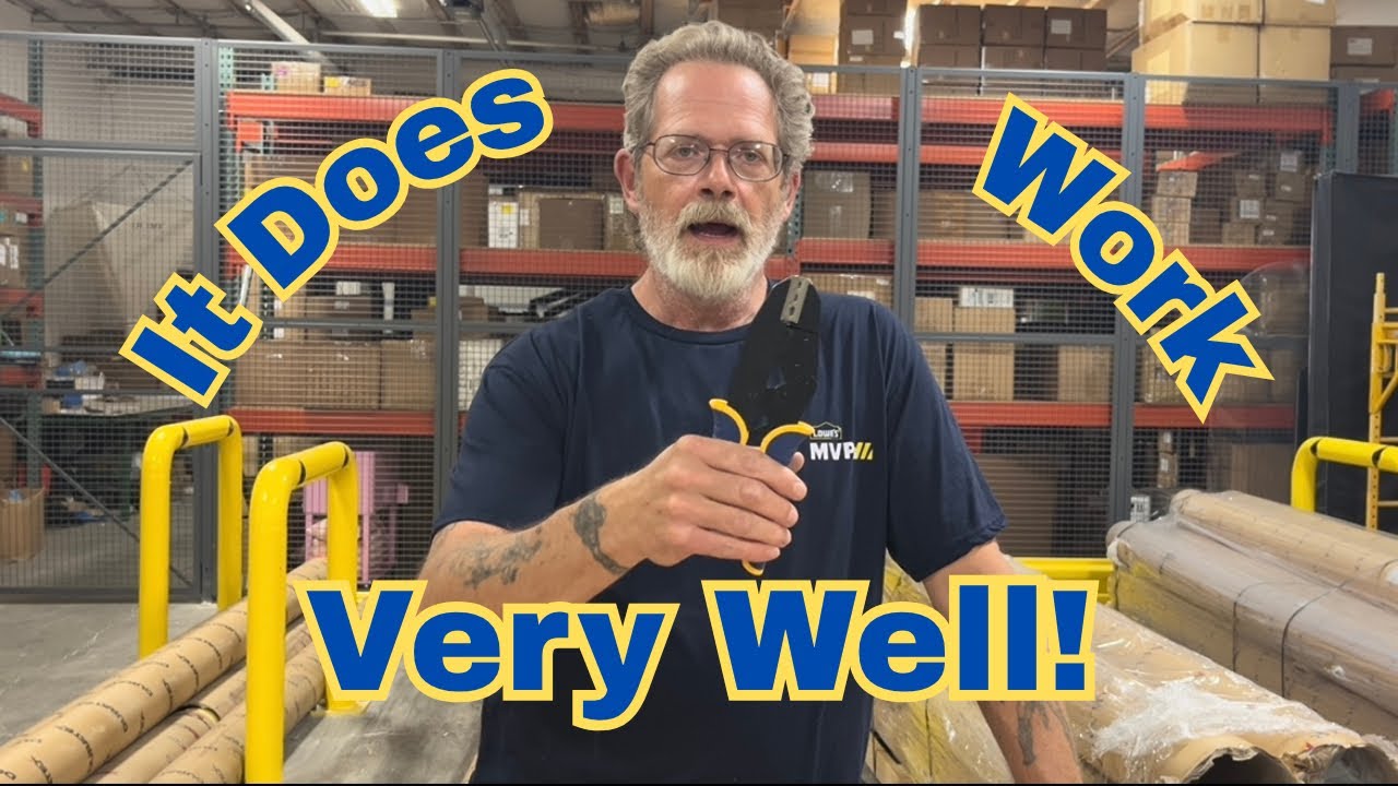
Apache Ranch Reviews: the kit and crimping workflow
Use the video to orient yourself to the components and handling. The checks below are an installation guide—not a claim that the video certifies electrical performance, pull strength or water resistance.
Watch on YouTube → Creator: Apache Ranch Reviews. The video's description includes advertising and affiliate-commission disclosures.
What is in the reviewed system?
Two consumables. Separate tools.
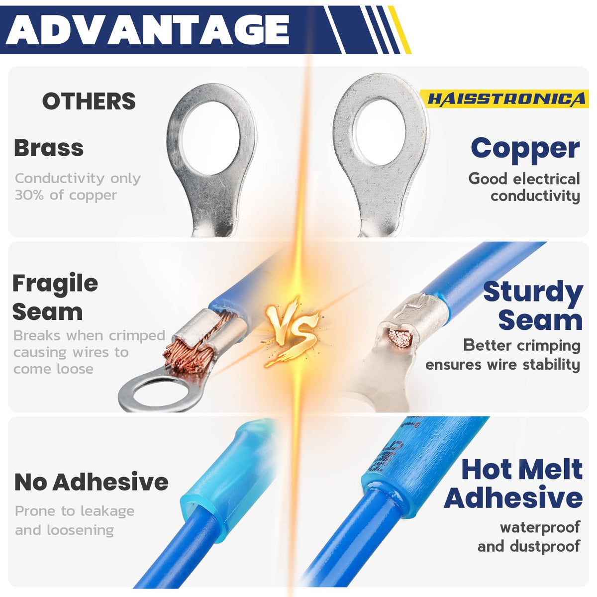
The tinned-copper barrels form the mechanical and electrical connection. Match the exact conductor size and construction to the connector.
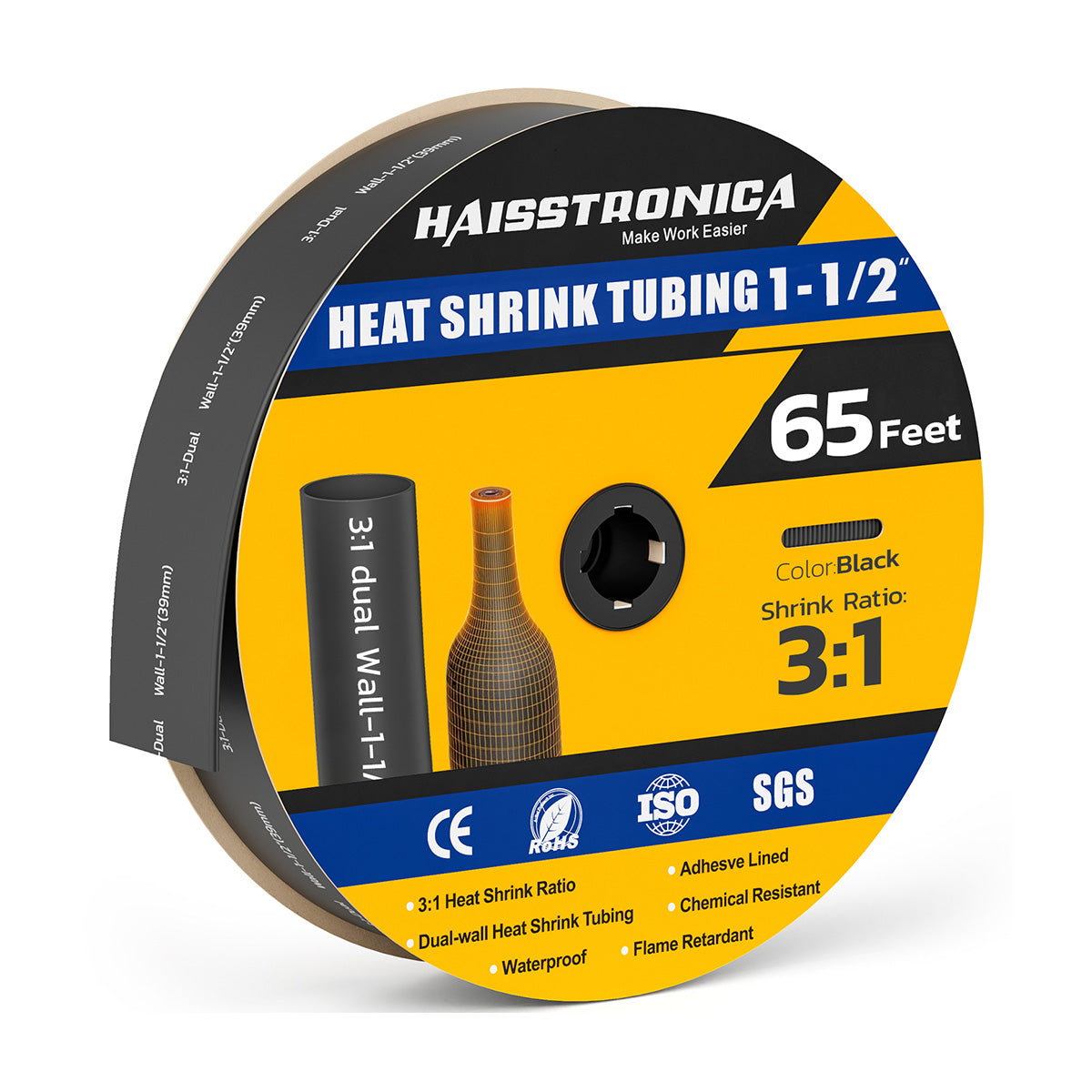
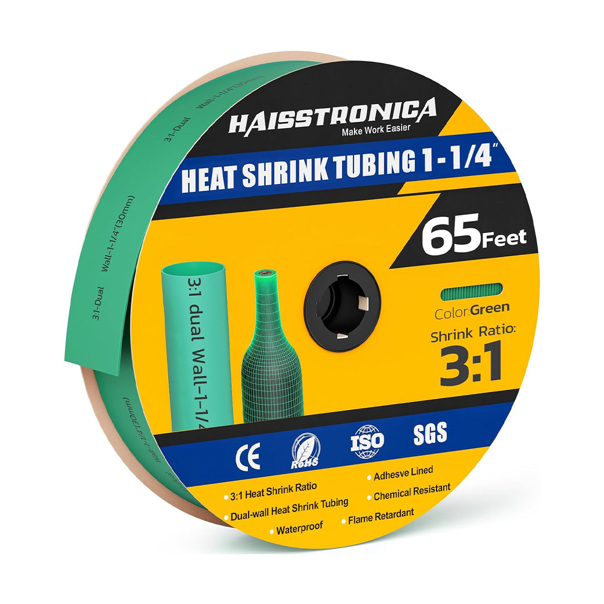
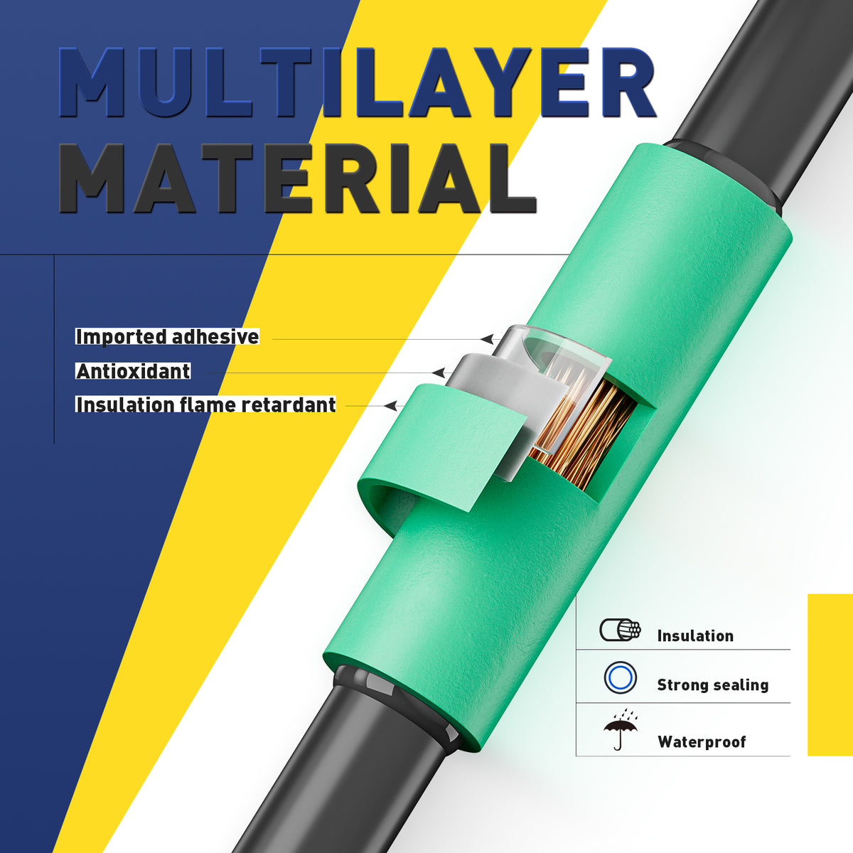
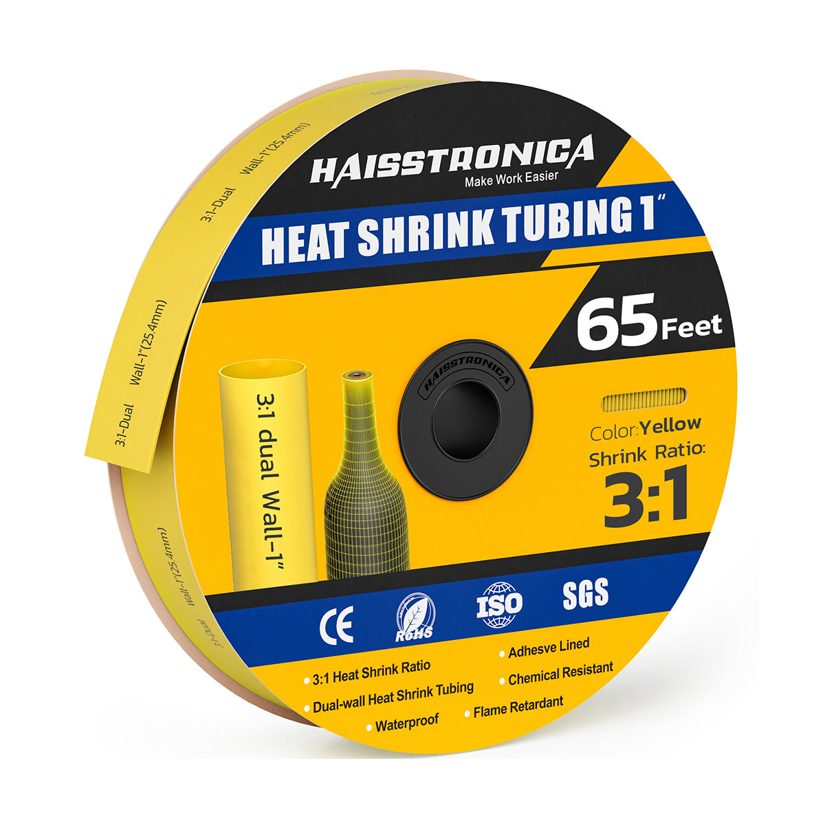
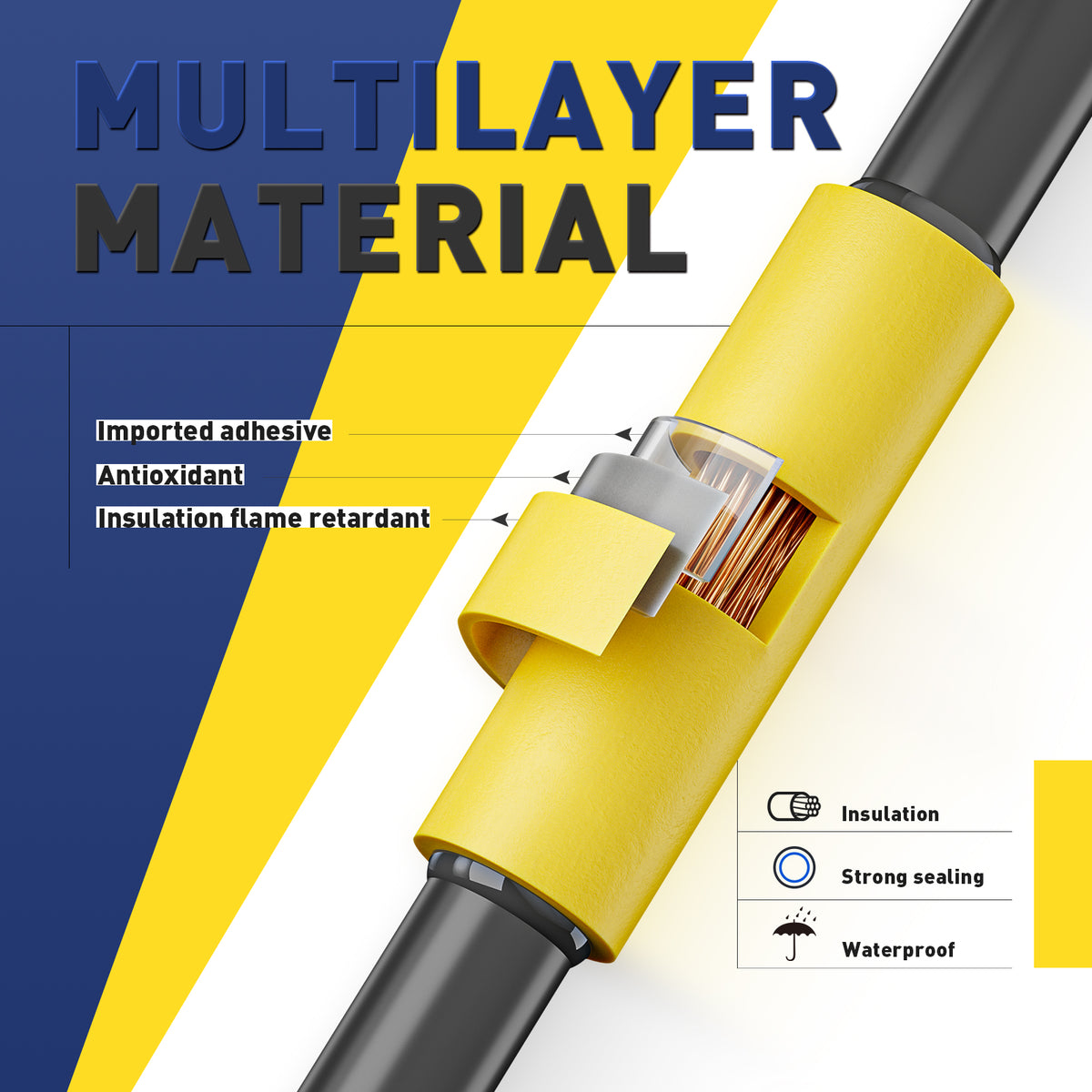
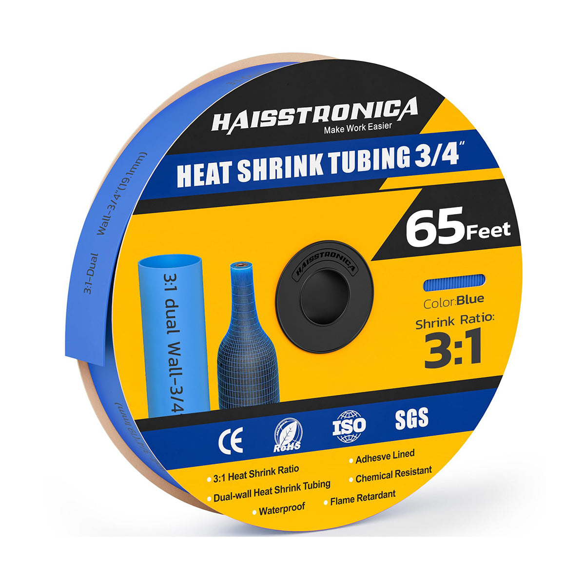
The tubing covers the completed crimp. Confirm the supplied sleeve's size, length, adhesive lining and application limits before use.
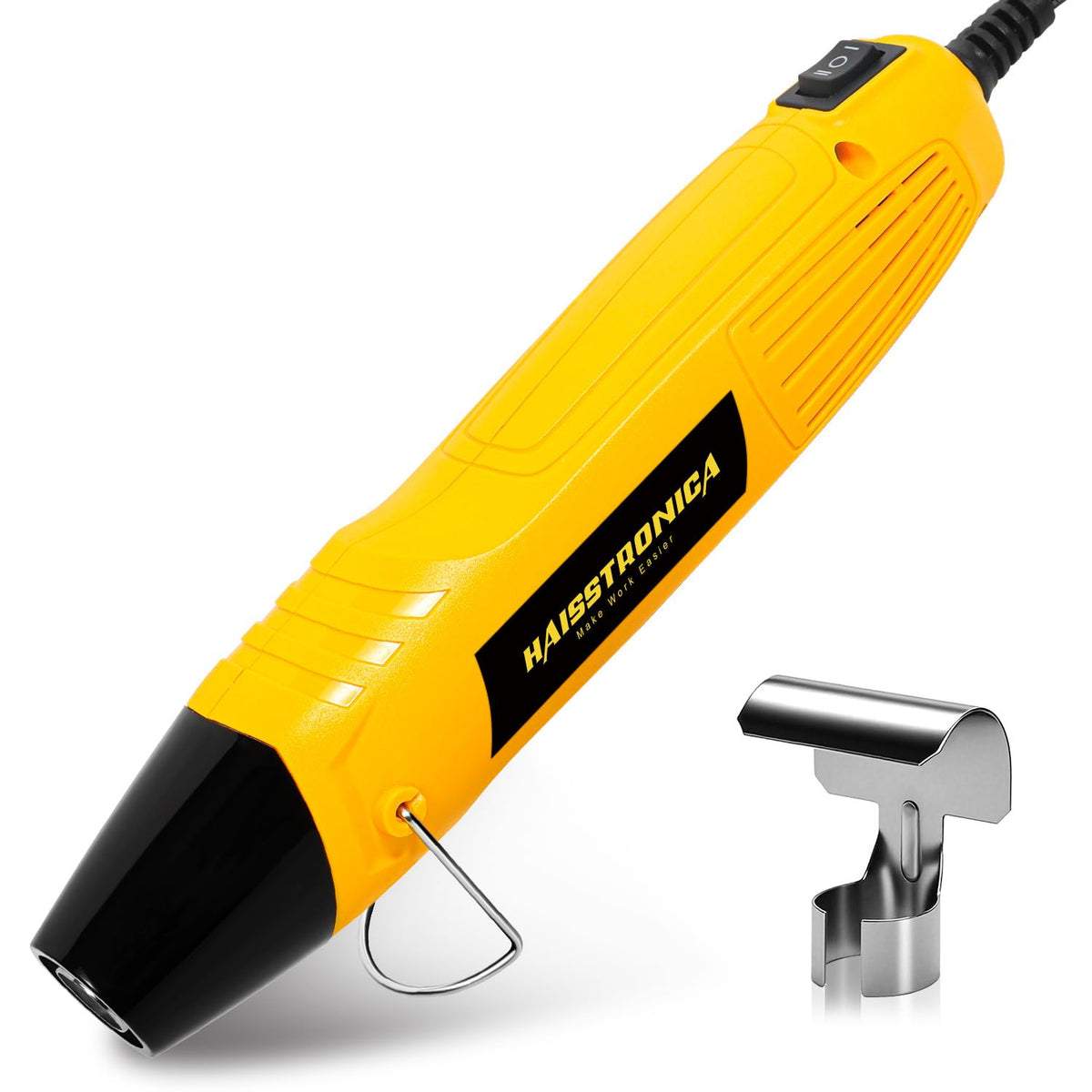
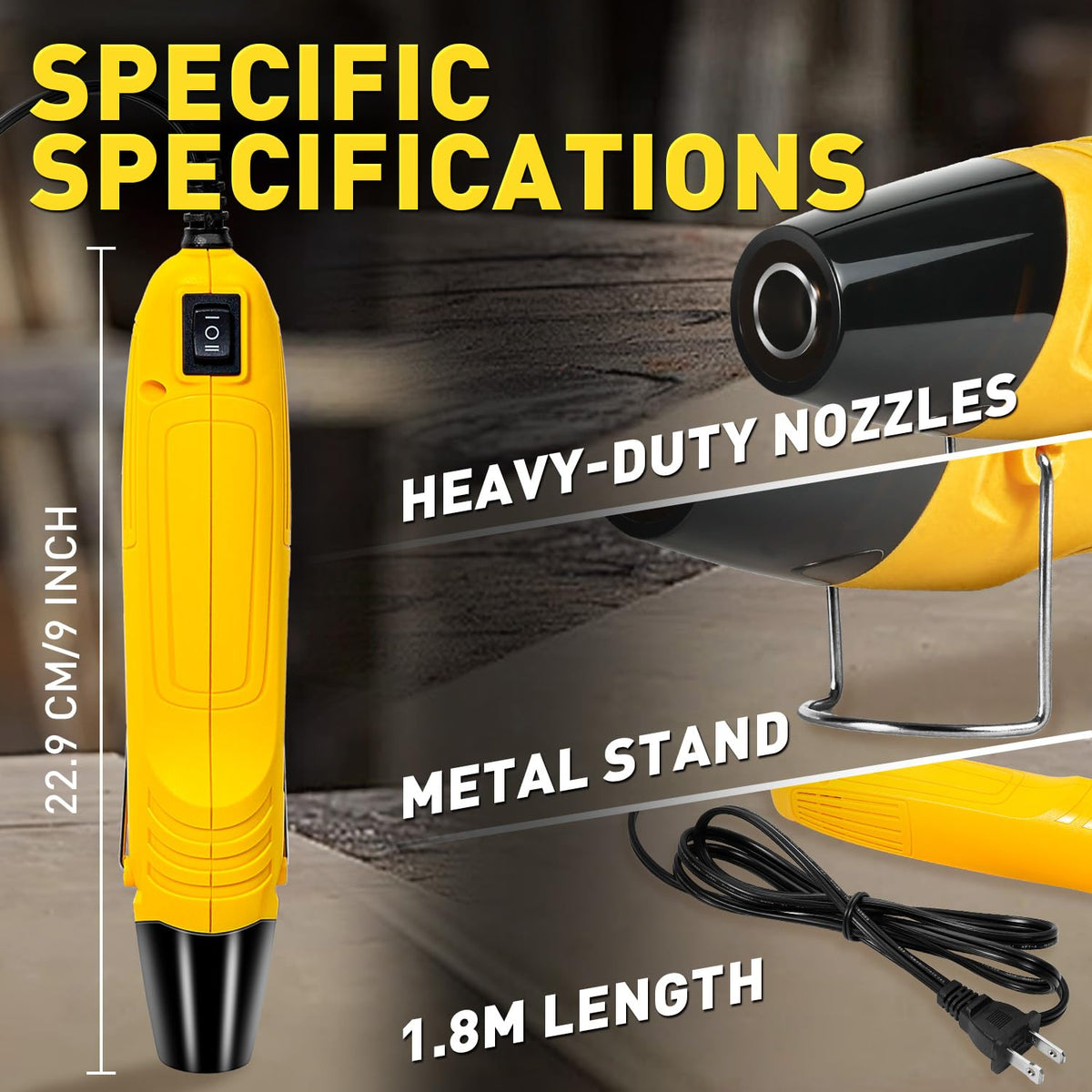
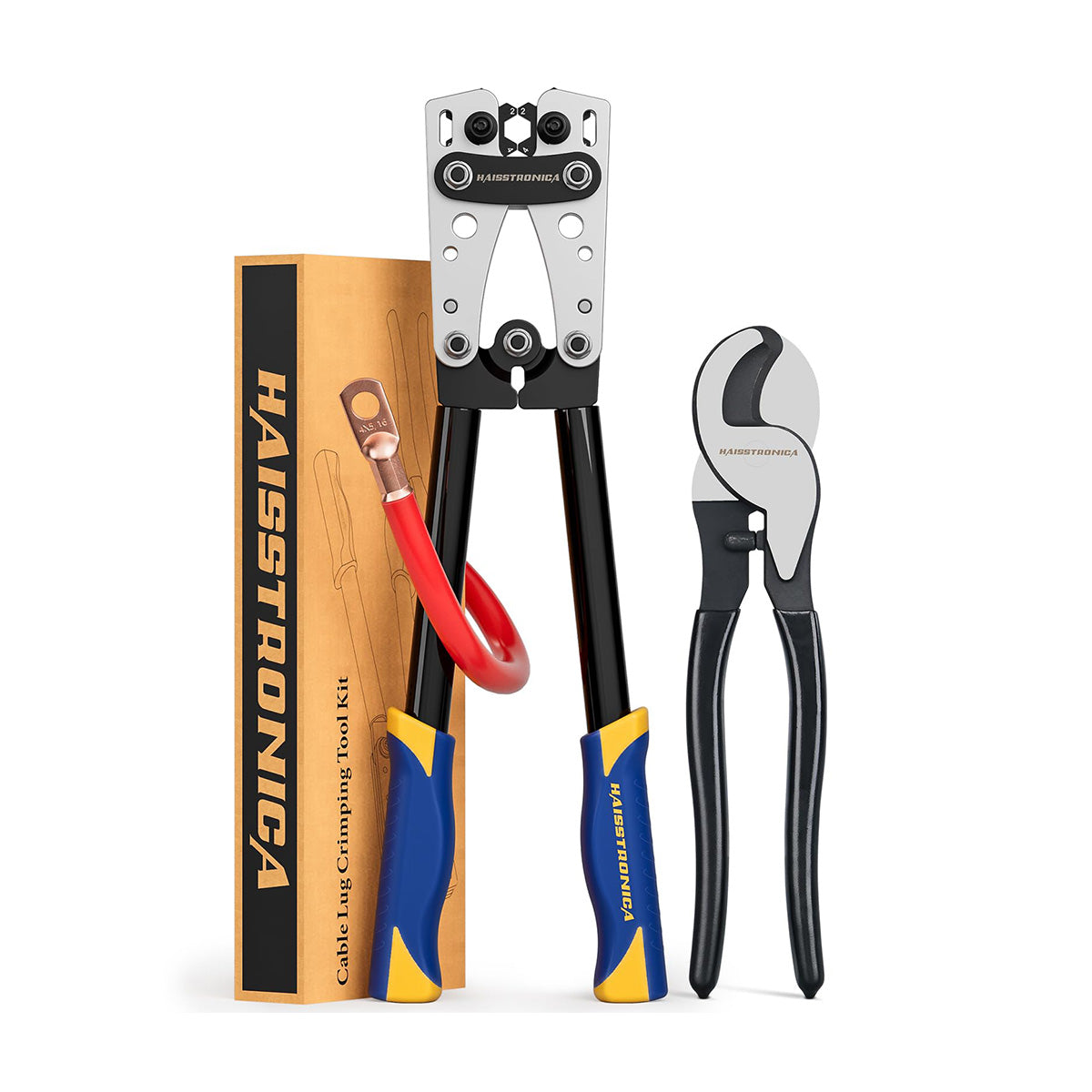
A suitable wire stripper/cutter, a matched non-insulated-terminal crimper and a controlled heat source. The reviewed connector-and-tubing pack is not a complete tool kit.
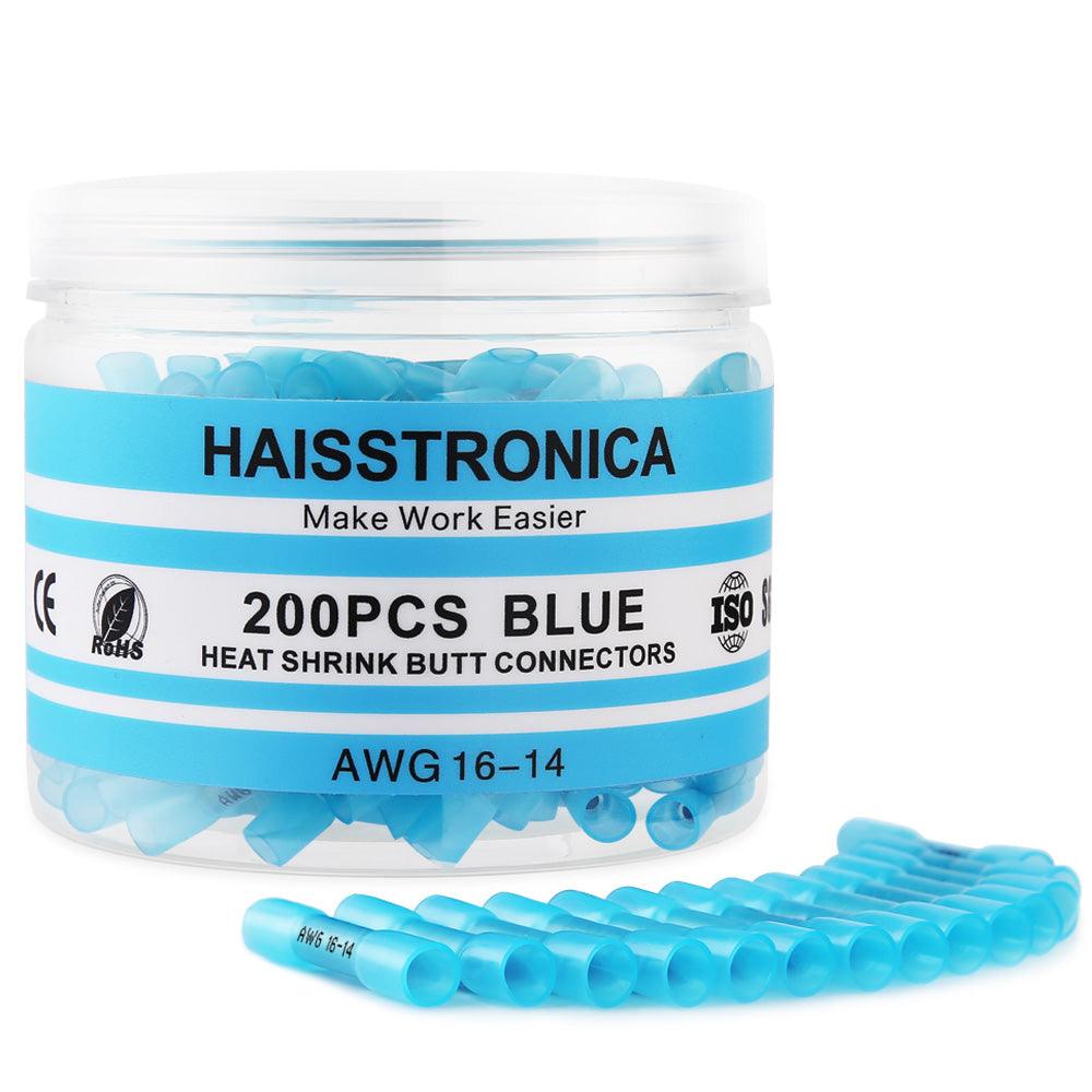
Check the gauge before ordering. The video description identifies a 16–14 AWG set with 100 connectors and 100 tubing pieces. The linked product page currently shows a 14–12 AWG selection. Do not treat these as the same wire-size variant; confirm the selector, package markings and contents for your order.
Tools sold separately.
Browse Non-Insulated Connectors → For other sizes, select a product explicitly rated for your wire rather than relying on a broad family-size chart.
Preparation · do this before joining the wires
Park the tubing on the wire first.
Disconnect and verify power is off. Select the barrel, tube and die before stripping. If there will be no free wire end afterward, slide the unheated tubing onto one wire and move it away from the work area before crimping.
- Match the conductorUse the connector's stated wire range, conductor material and strand construction. Do not cut strands off to force a larger wire into the barrel.
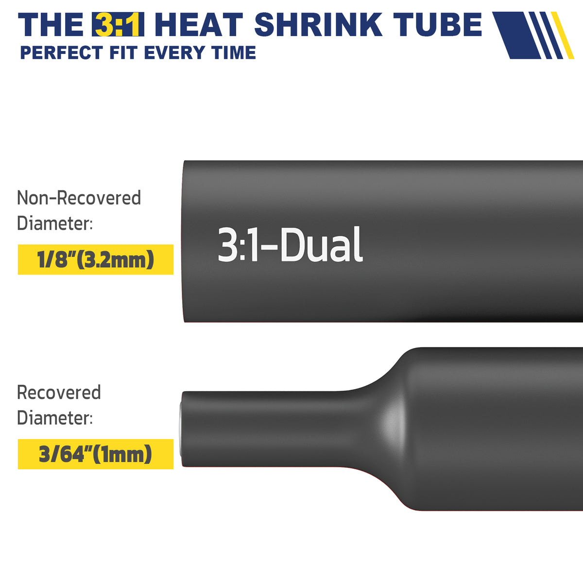
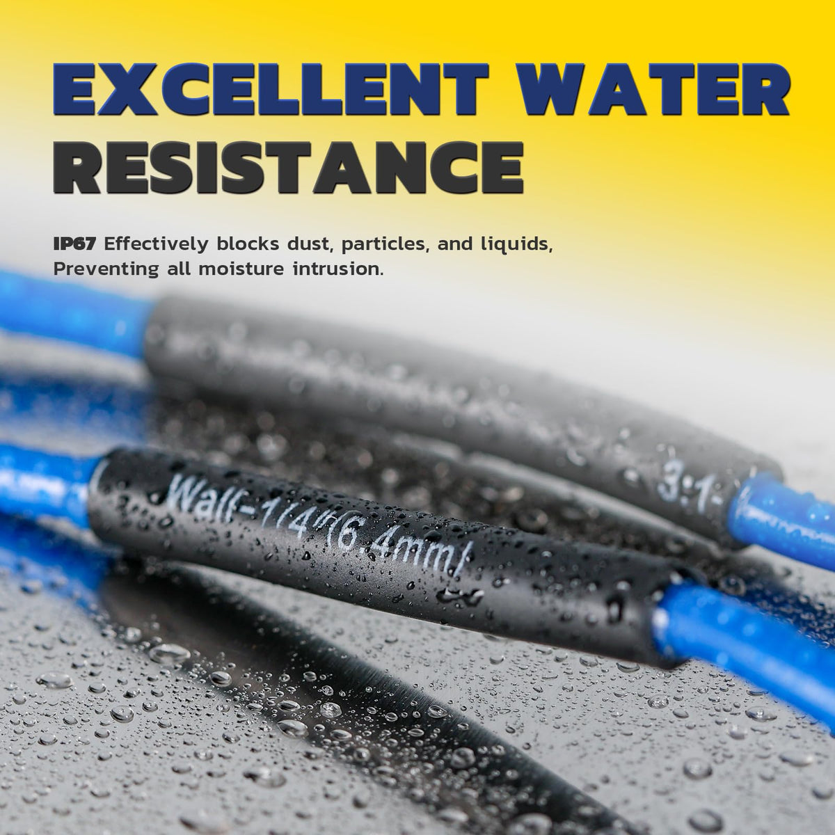
- Match the tubeIts expanded diameter must pass over the joint, while its recovered size must fit the wire insulation. A 3:1 ratio alone does not establish the correct size.
- Set the strip lengthFollow the connector's required length and insertion depth. Keep all strands intact and keep insulation out of the conductor-crimp zone.
Crimping stage · select the bare-terminal tool
Make the metal joint before covering it.
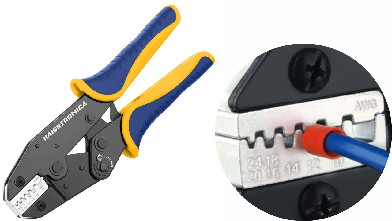
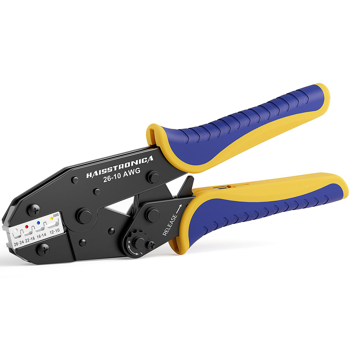
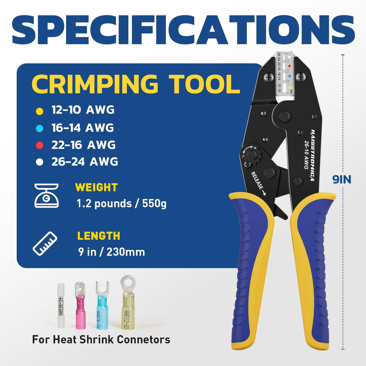
Use a die intended for this non-insulated barrel
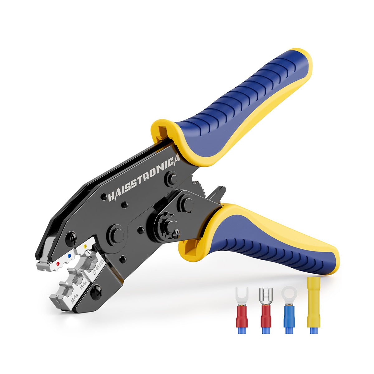
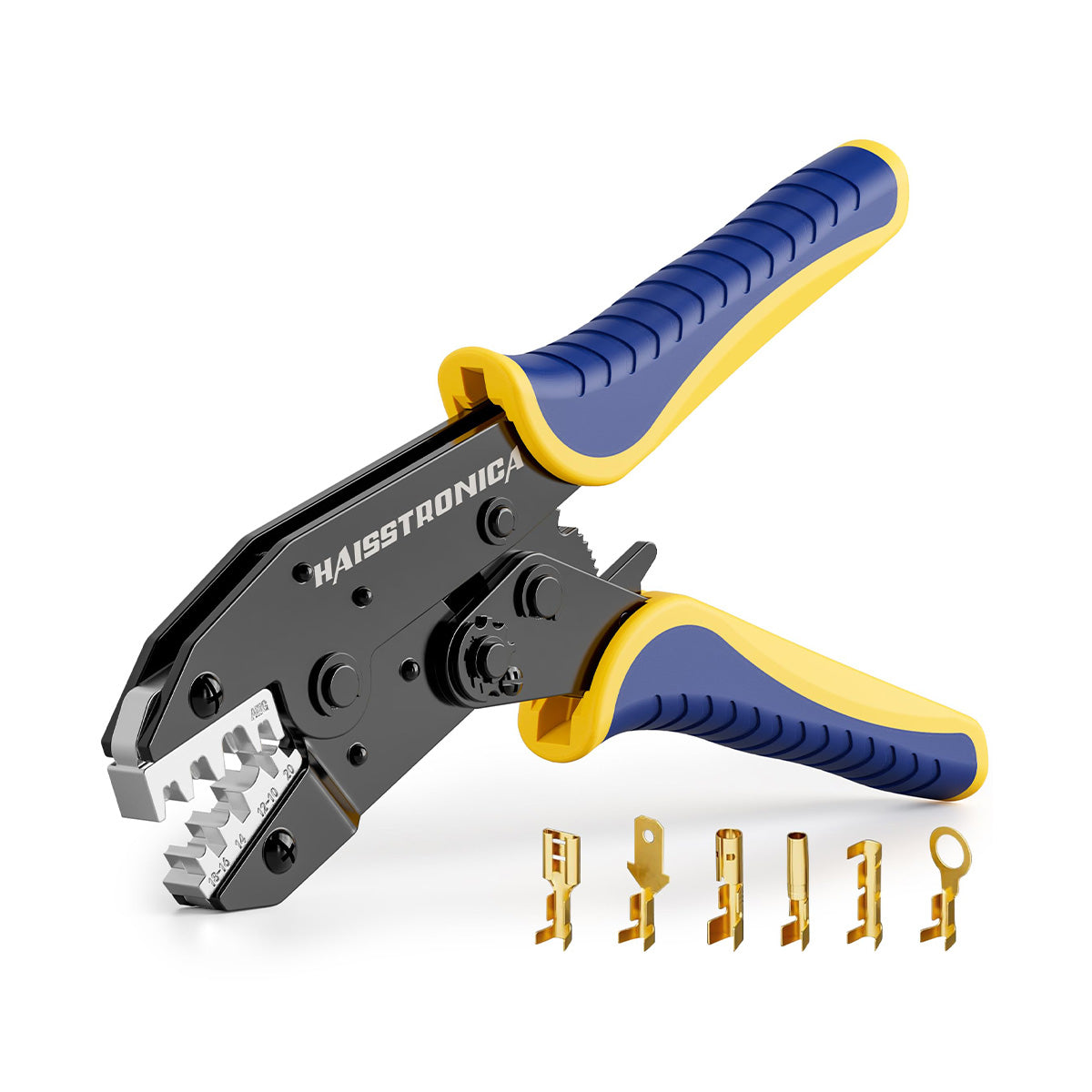
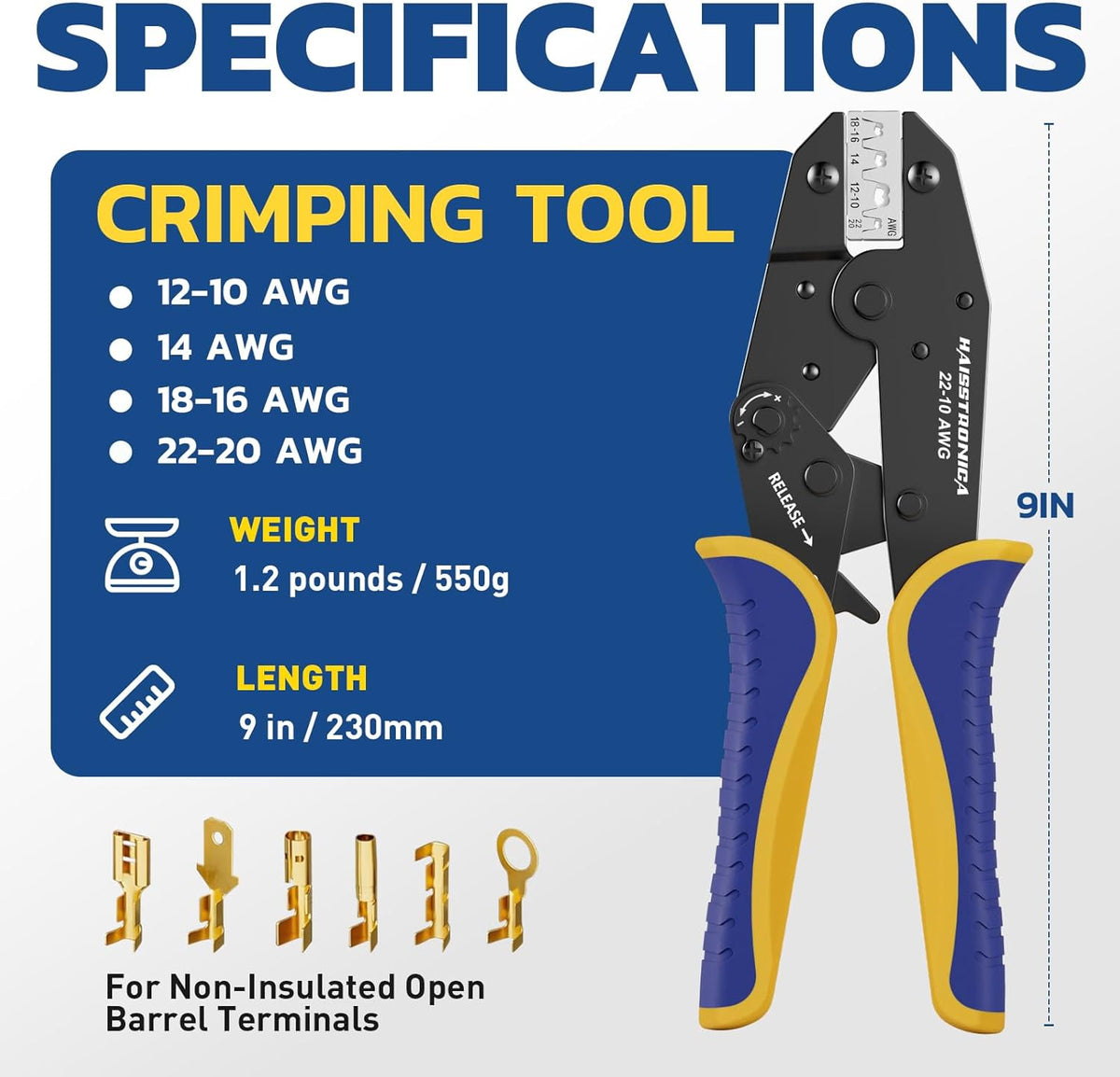
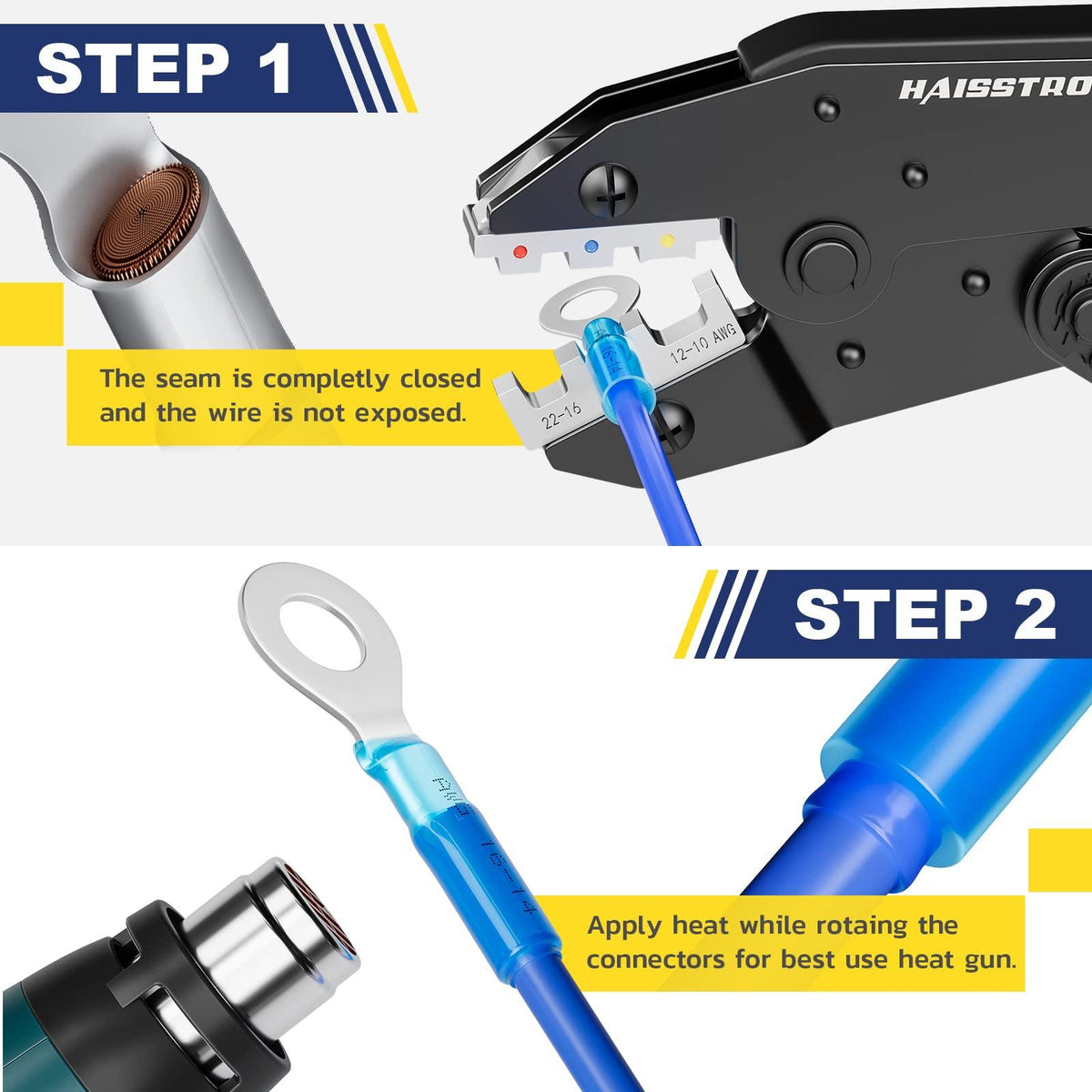
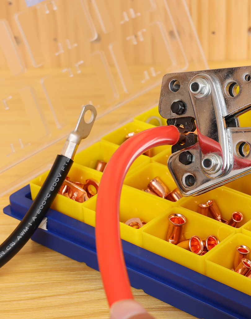
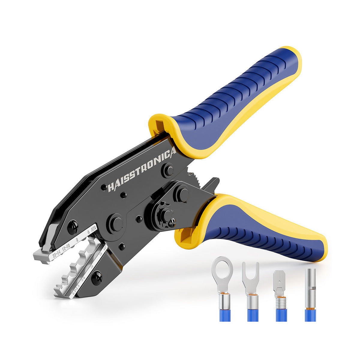
The linked AWG 22–6 ratchet crimper is designed for non-insulated terminals. Match its die cavity and profile to the actual barrel and wire; its overall range does not make every non-insulated connector compatible.
- Insert each conductor to the connector's specified depth.
- Place the barrel in the specified die location and complete the prescribed crimp cycle on each side.
- Inspect the exposed barrel and wire entry points before moving the tubing over them.
Do not substitute by name alone. An open-barrel crimper or a heat-shrink-terminal crimper can have a different die profile. Confirm compatibility with this closed-barrel splice.
The inspection point
What a visible crimp can—and cannot—tell you
- Conductor entryCheck for missed strands, damaged copper, incorrect insertion or insulation trapped in the conductor barrel.
- Barrel conditionLook for misplaced compression, cracks, sharp projections and deformation outside the intended crimp zone.
- Required verificationCarry out the connector or equipment maker's specified retention and electrical checks. A visual inspection does not establish internal compression, resistance or calibrated pull strength.
A failed crimp needs a new connection. Correct the setup and replace the failed connector. Heat shrink must not be used to hide a loose or damaged joint.
Heat-shrink stage · position, recover and cool
Bring the sleeve over the verified joint.
Center the tube over the barrel with the insulation overlap required by the tubing and connector instructions. Confirm there is enough clearance to heat the full circumference safely.
Use controlled hot air for the sealing step
- Use the temperature, distance and heating sequence specified for the tubing. Keep heat moving rather than scorching one spot.
- Check recovery around the wire insulation at both ends. For adhesive-lined tubing, look for the specified indication of adhesive flow.
- Stop if the tube splits, chars or damages the wire jacket. Let the splice cool without movement.
- Support the wiring so repeated bending and cable tension do not load the splice.
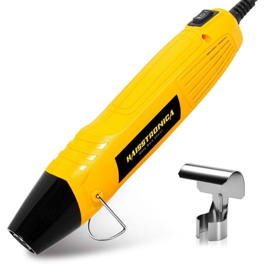
3:1 describes shrink capability, not universal sealing. It does not prove a waterproof rating or compensate for an incorrectly sized sleeve. Avoid open flame and keep heat away from fuel vapors and flammable materials.
View the connector + tubing kit →
Browse Heat Shrink Tubing → Match both diameter and coverage when replacing or buying tubing separately.
Choose by the installation
Does this workflow fit your project?
Automotive / low-voltage repair
Useful when you can inspect and support the splice
Check the vehicle's repair method, wire size, heat exposure and routing. Allow room for the separate sleeve and strain relief. Safety-critical circuits may require a specific connector or harness replacement.
Marine / exposed routing
Verify the complete sealing system
Confirm conductor material, adhesive-lined tubing, environmental ratings and cable support. Neither tinned copper nor a 3:1 ratio alone establishes suitability for saltwater exposure or continuous submersion.
Industrial / equipment maintenance
Let the equipment specification decide
Confirm voltage, temperature, conductor construction, fluids, enclosure requirements and the permitted repair method. A hands-on review is not a code approval or qualification test.
Our conclusion
Choose it for the inspection point—not an automatic performance upgrade.
The separate-component approach makes sense when you want access to the bare barrel before insulation and can manage tube selection, positioning and controlled heating. If reducing loose parts matters more, a compatible pre-insulated heat-shrink connector offers another route.
Before you order
Quick answers
Is the reviewed size the same as the current product selection?
Not necessarily. The video description identifies 16–14 AWG, while the linked listing currently shows 14–12 AWG. Use the current selector and package specification, and confirm the required size before ordering.
Can I add the tubing after crimping both wires?
Only if a free wire end and sufficient access allow it. Otherwise, place the tube on a wire before completing the splice and keep it clear until the crimp passes inspection.
Does 3:1 heat shrink make the splice waterproof?
Not by ratio alone. Correct sizing, suitable adhesive lining, intact wire insulation, installation quality and the product's environmental rating all matter.
Are tools included with the connector-and-tubing pack?
Do not assume so. Prepare a suitable stripper/cutter, the specified crimper and a heat source, and check the exact product contents before purchase.
Work only on a de-energized circuit. Follow the connector, tubing, tool and equipment instructions; have regulated or safety-critical work handled by appropriately qualified personnel.