
Crimping tool styles guide
Match the tool to the terminal—not just the wire gauge
Crimp quality is controlled by three exact matches: conductor size, connector geometry and die profile. Manual, ratchet, automatic, hydraulic, heavy-duty and connector-specific tools are built for different workloads and terminal shapes. Choose by the job first; product selection comes second.
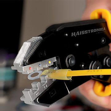
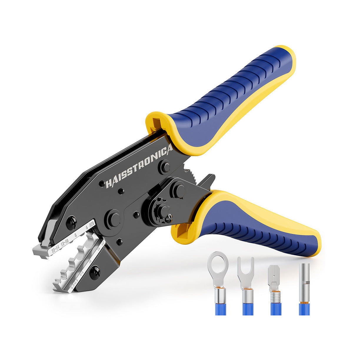
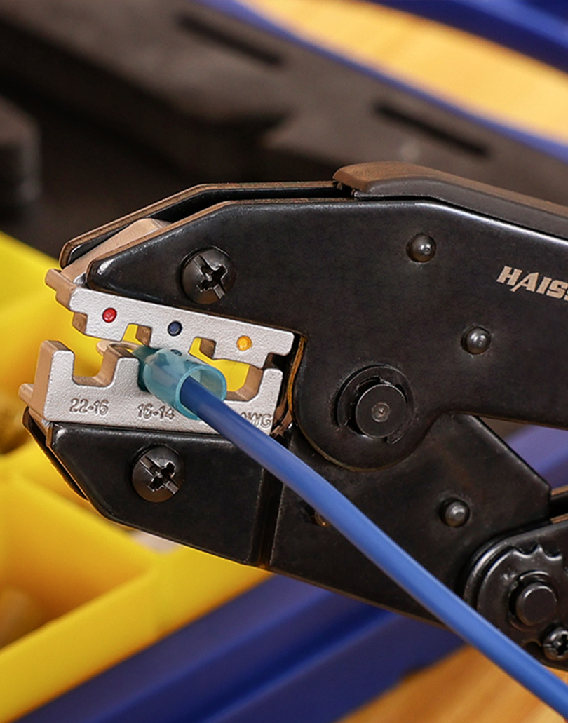
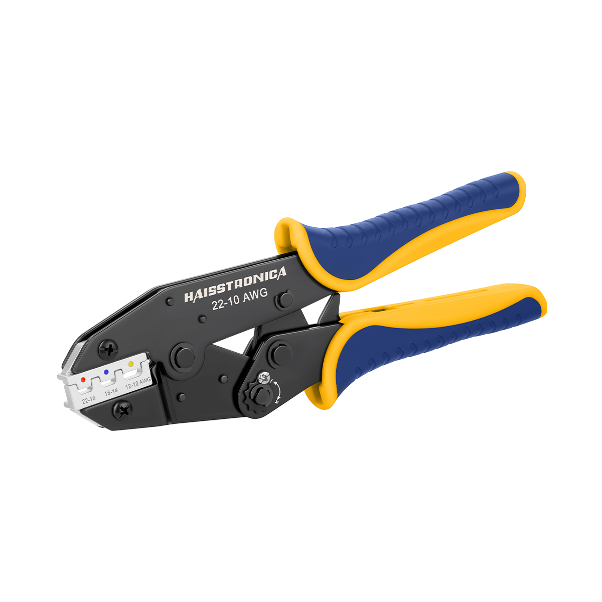
Ratchet crimper
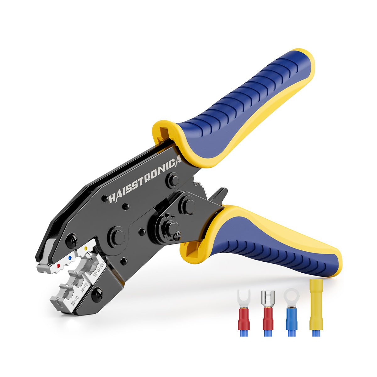
A full-cycle mechanism improves consistency when the die profile matches the terminal family and AWG.
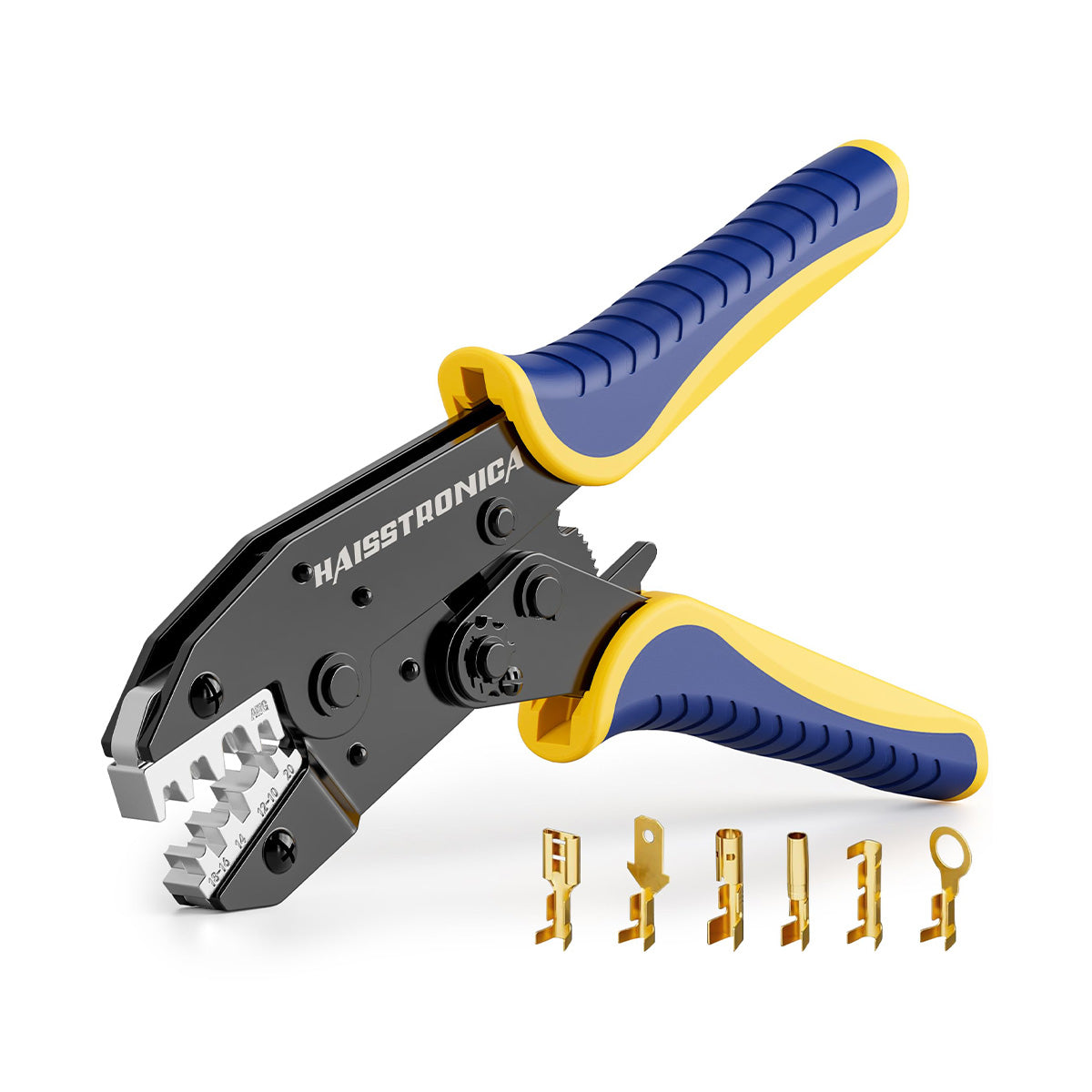
Open-barrel crimper
Separate conductor and insulation wings need the correct B-crimp geometry and accurate contact positioning.
Ferrule crimper
Square or hex profiles form the ferrule for the equipment terminal block specified by the application.
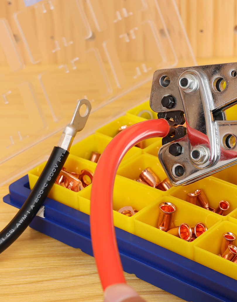
Battery-lug crimper
Large-gauge cable and thick copper lugs require a tool and die range rated for the exact conductor size.
Seven common tool styles
Tool type changes force, geometry and repeatability
The handle shape is not the main difference. The mechanism controls how force reaches the terminal and whether the finished profile matches the connector design.
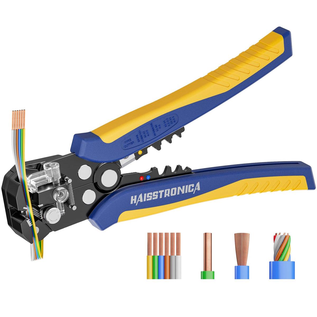
Manual crimper
Simple plier-style tools suit low-volume work only when the cavities are correctly shaped and the operator can apply consistent force.
Ratchet crimper
The ratchet completes a controlled cycle before release, making terminal work easier to standardize across repeated jobs.
Automatic crimper
Powered systems can feed, position and crimp components rapidly. They require setup, applicator control and scheduled validation.
Hydraulic crimper
Hydraulic force reduces operator effort on large lugs, but die size, lug specification and verified compression remain essential.
Heavy-duty crimper
Long handles or compact compound mechanisms create leverage for thick lug barrels within a published cable range.
Connector-specific crimper
Open-barrel, ferrule, coaxial and modular contacts need dies shaped for their conductor and insulation support features.
Interchangeable-die kit
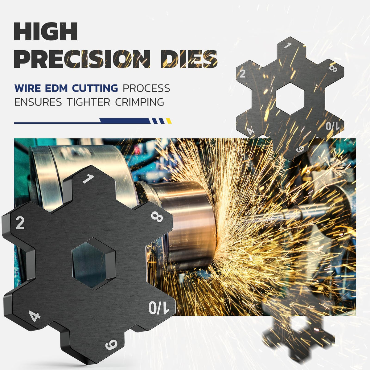
A multi-die set reduces tool count when each installed die is clearly marked, securely seated and matched to the terminal family.
Selection table
Filter by AWG, connector and workload
Use the connector family to choose the die geometry, then confirm the conductor range and expected job volume.
| Job | Connector geometry | Workload | Recommended tool path |
|---|---|---|---|
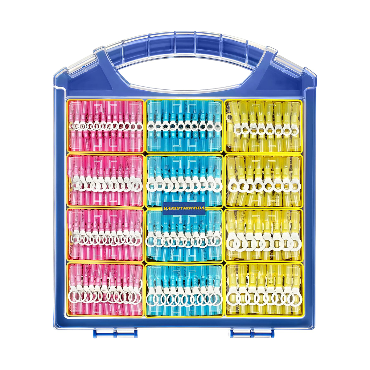
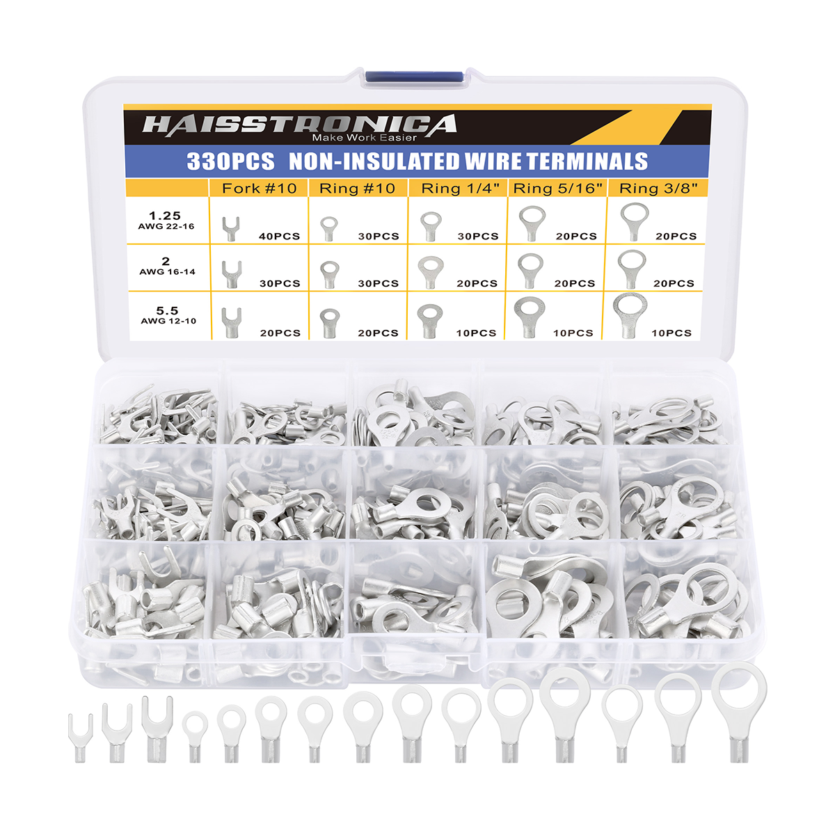
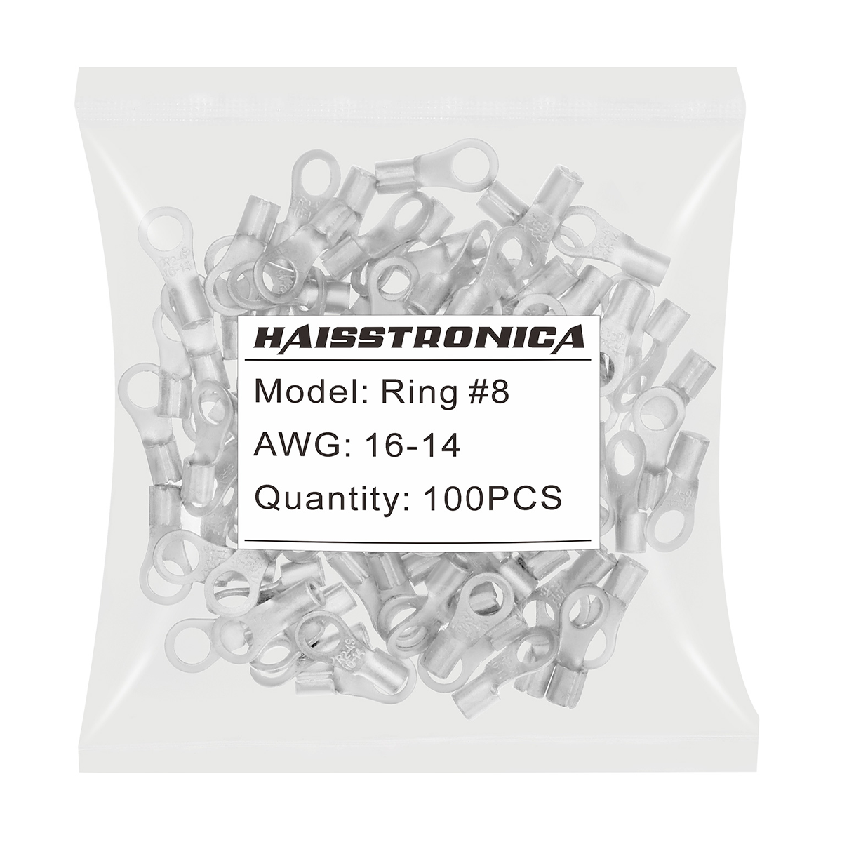
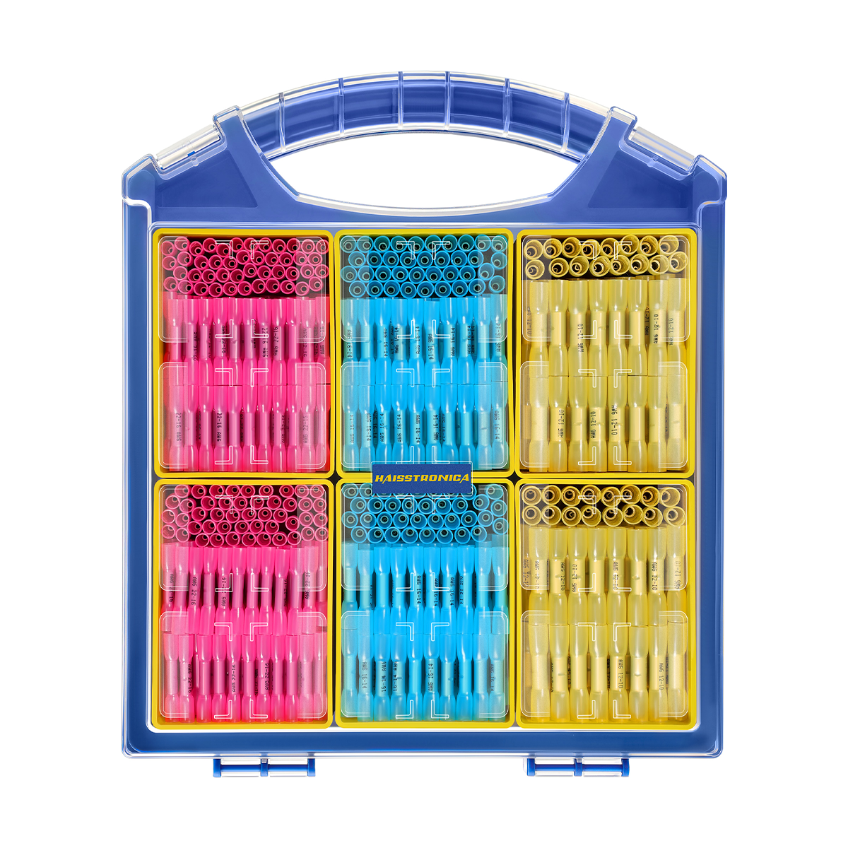
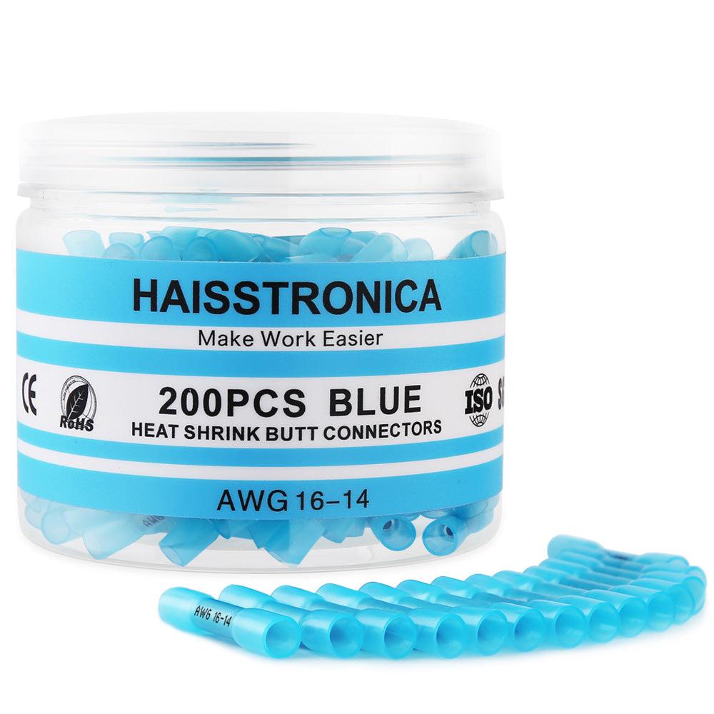
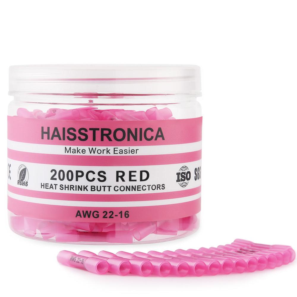
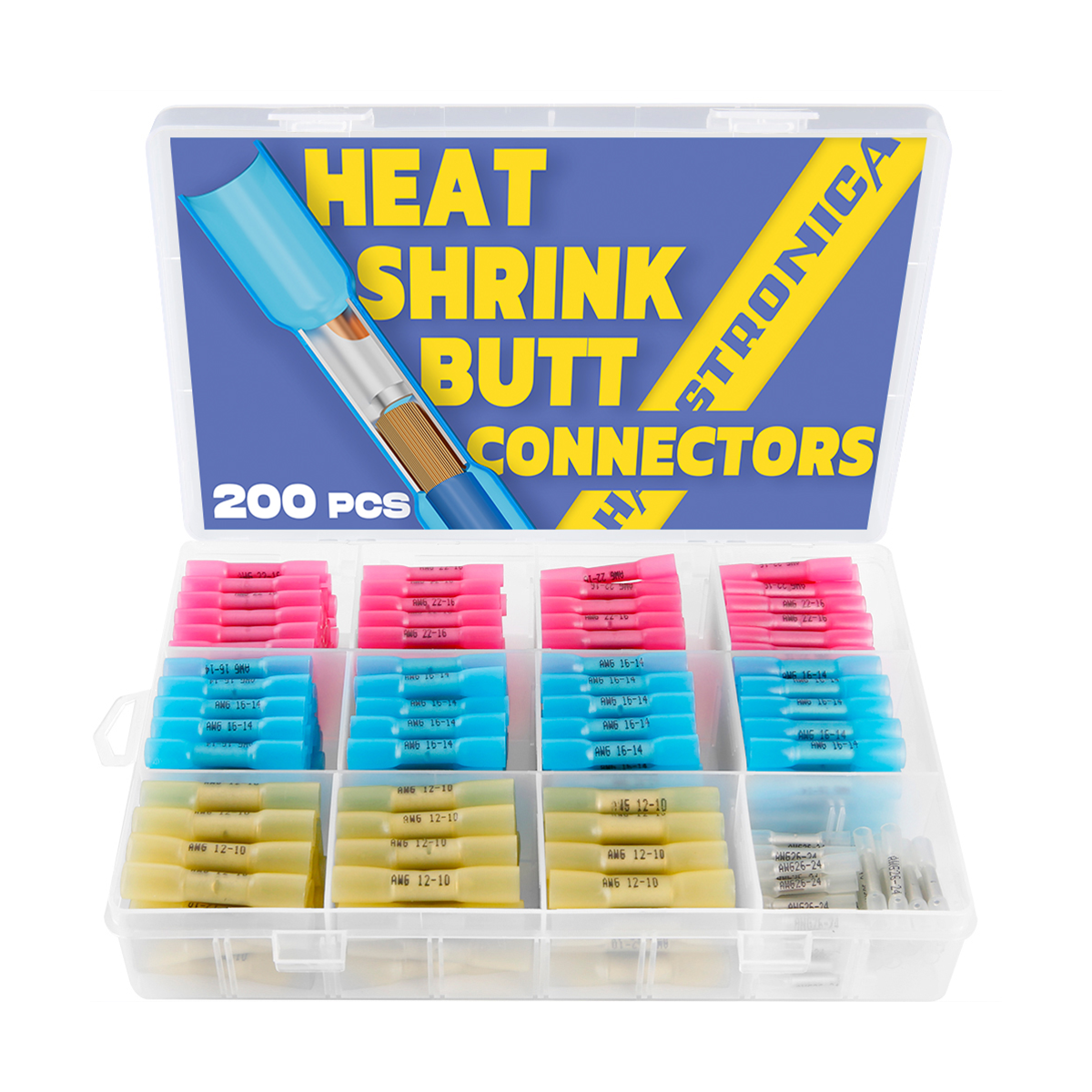
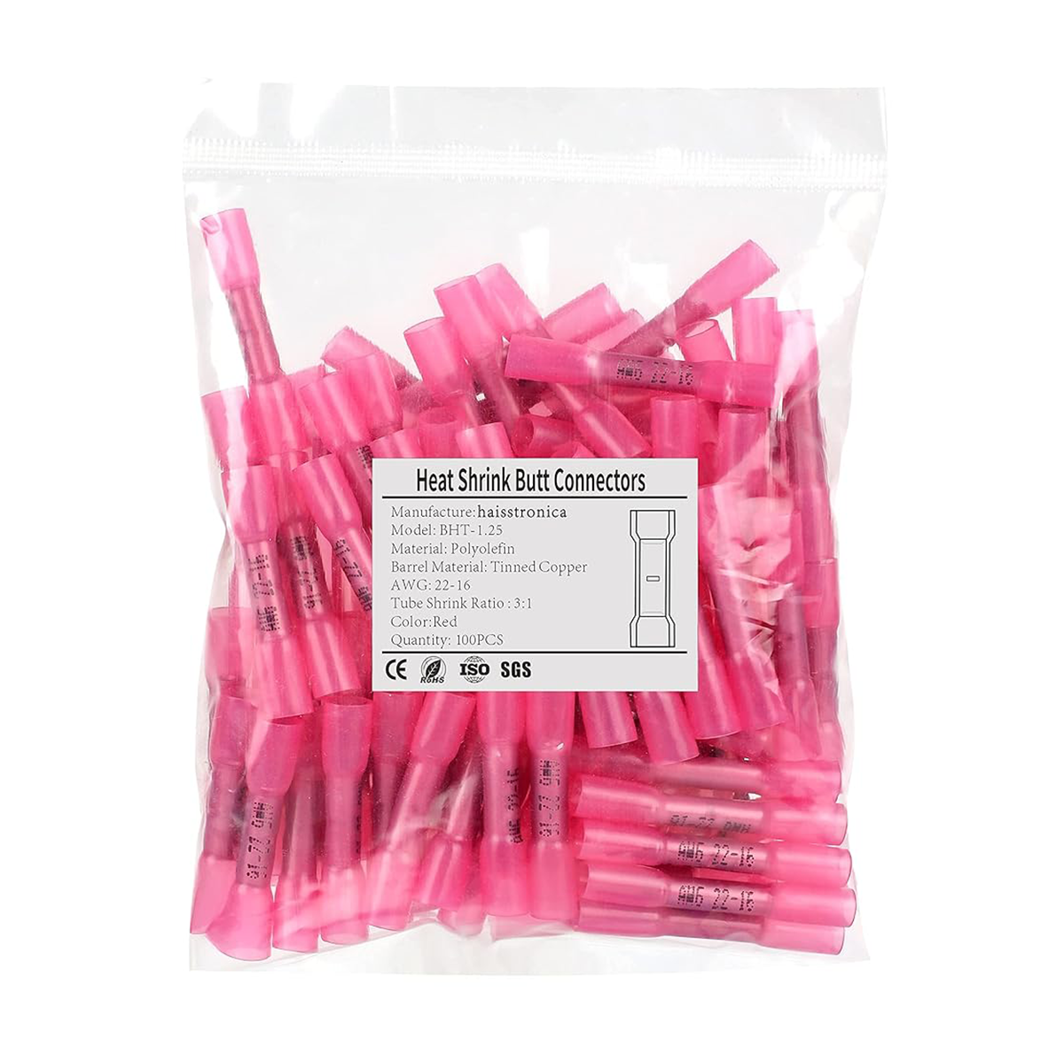
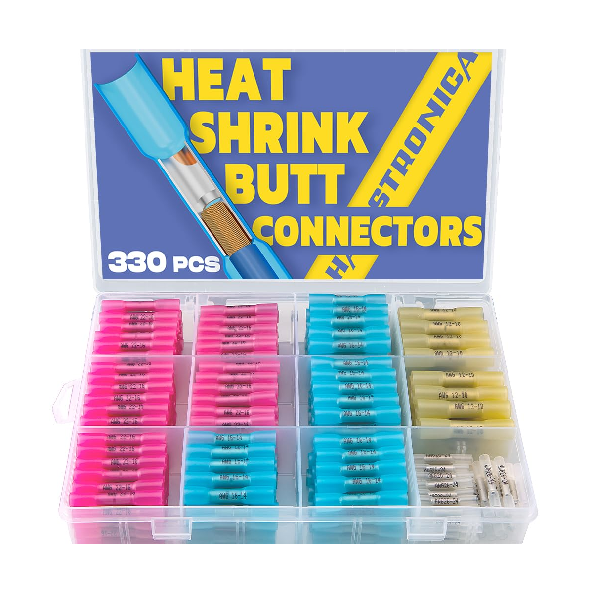
| Heat-shrink or insulated terminals | Closed barrel with colored insulation | Occasional to repeat | Ratchet crimper → |
| Automotive pins and contacts | Open barrel with conductor and insulation wings | Repair or harness assembly | Open-barrel crimper → |
| Control cabinets | Bootlace ferrule | Repeat panel work | Ferrule crimper → |
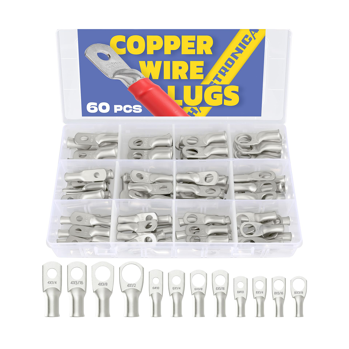
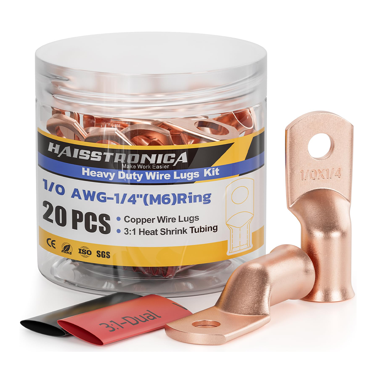
| Battery and inverter cables | Thick copper lug barrel | Low volume, high force | Battery-lug crimper → |
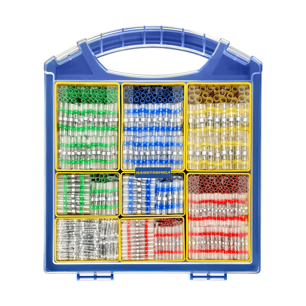
| Mixed connector bench | Several terminal families | Service and field kit | 8PCS tool kit → |
Five product-specific paths
Go directly from connector geometry to the right tool
Each path below keeps the tool recommendation beside the connector type it is designed to form.
Path 1 · insulated and heat-shrink terminals
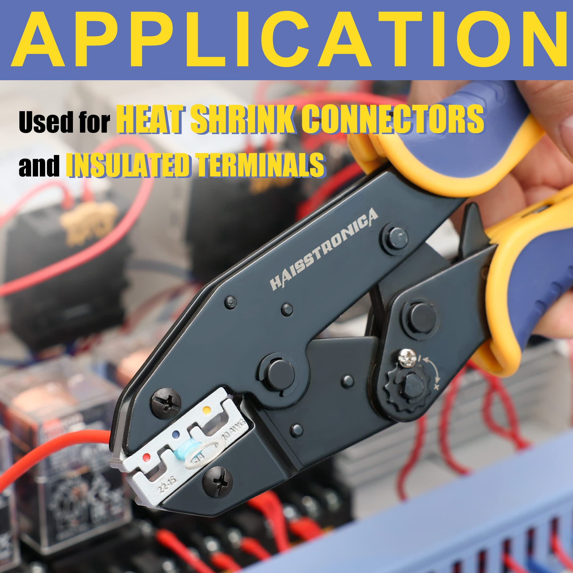
Ratchet crimper for repeatable closed-barrel work
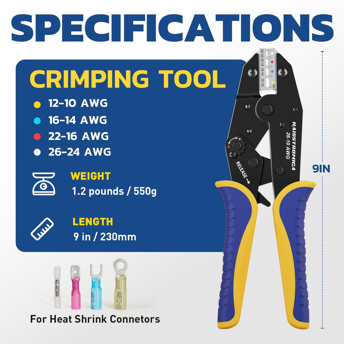
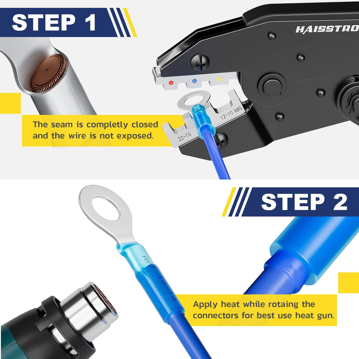
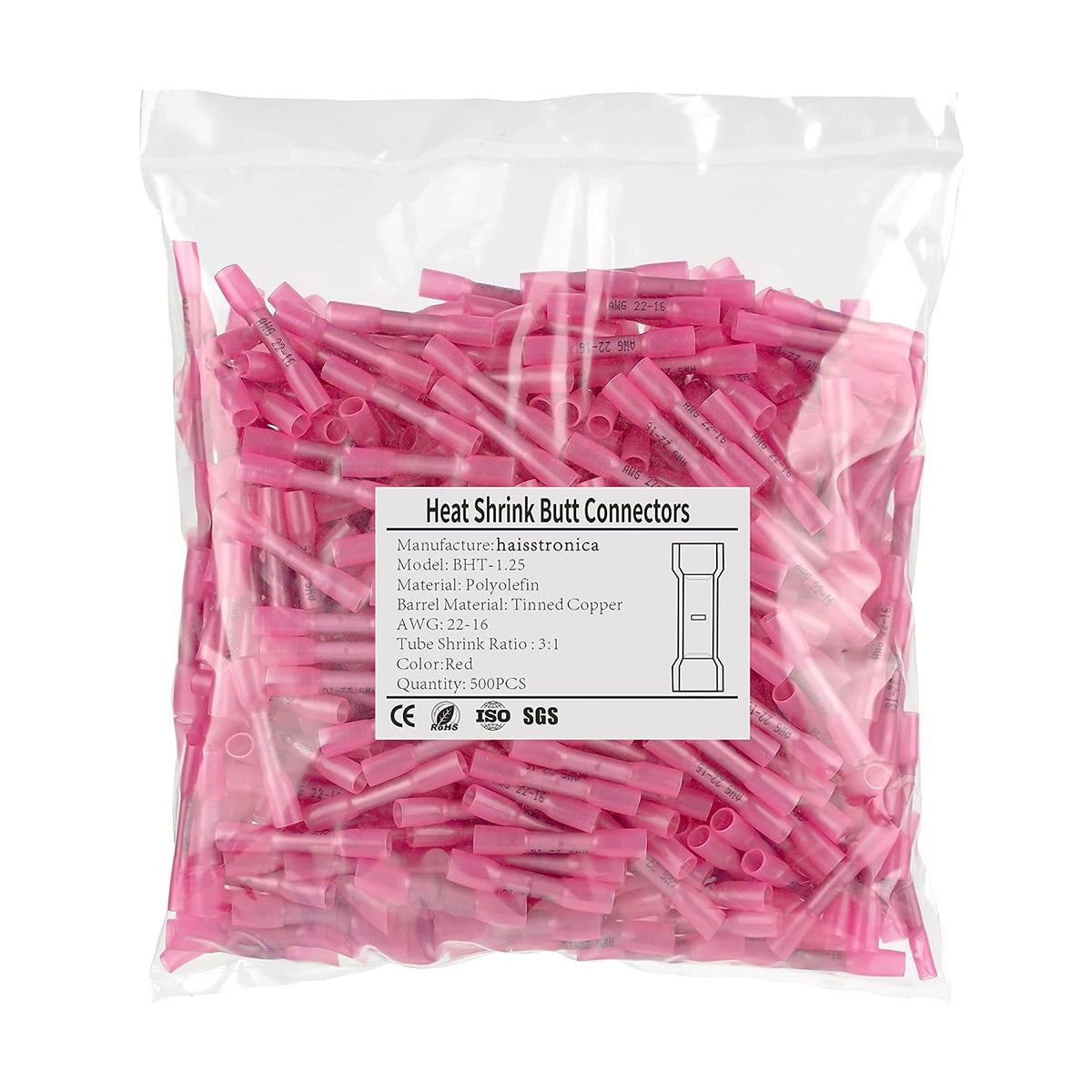
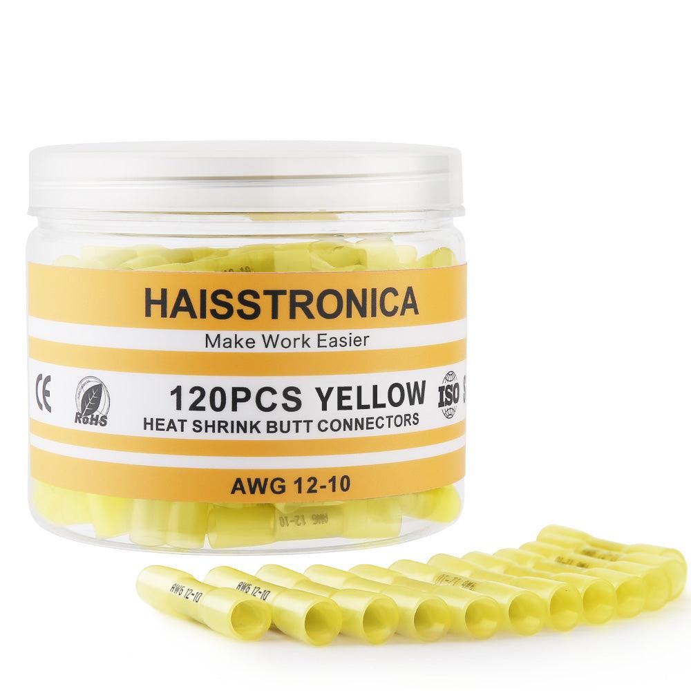
Use this path for compatible butt, ring, spade and quick-disconnect terminals in the published AWG range. The ratchet supports a complete cycle, but correct cavity placement still determines the crimp.
- Match terminal family and AWG to the marked cavity.
- Place the metal barrel—not the sleeve edge—inside the die.
- Complete the cycle, inspect the impression and pull-test.
Path 2 · automotive pins and open-barrel contacts
Open-barrel crimper for conductor and insulation wings
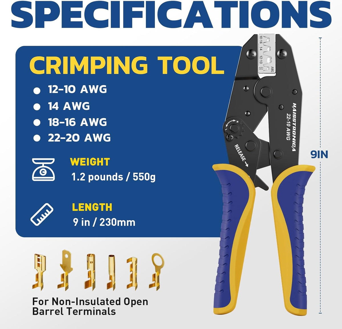
Open-barrel contacts are not ordinary insulated terminals. Their wings must fold into the intended profile: the inner set captures conductor strands while the outer set supports insulation.
- Confirm contact series, wire range and wing orientation.
- Position the contact before inserting the stripped conductor.
- Inspect both conductor and insulation-support crimps.
Path 3 · ferrules and terminal blocks
Ferrule crimper for compact stranded-wire ends
Use ferrules where the equipment terminal accepts them and the conductor range matches. Select square or hex crimp geometry according to the terminal block and installation specification.
- Strip to the ferrule barrel depth without exposed copper.
- Insert all strands fully before crimping.
- Check the finished profile for complete, even compression.

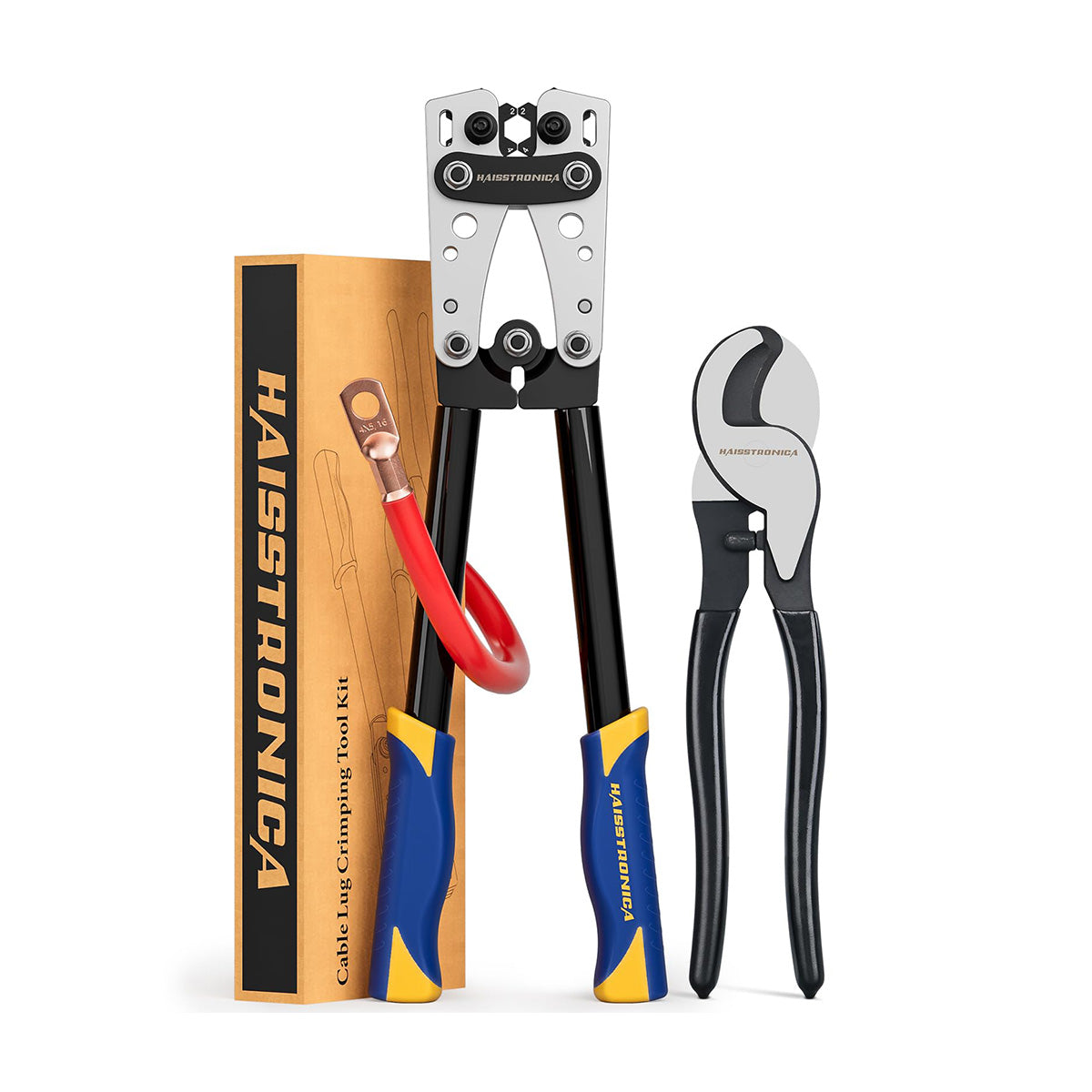
Path 4 · battery, inverter and solar cable
Battery-lug crimper for heavy copper barrels
Large cable requires more than handle leverage. Match the cable gauge, lug barrel, stud hole and die range as separate specifications. Never force a large lug into an undersized tool.
- Measure lug barrel depth before stripping.
- Use the die specified for the cable and lug—not appearance alone.
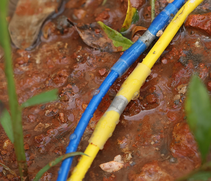
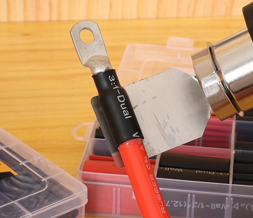
- Inspect every impression, pull-test and seal with suitable heat shrink.
Path 5 · mixed service bench and field kit
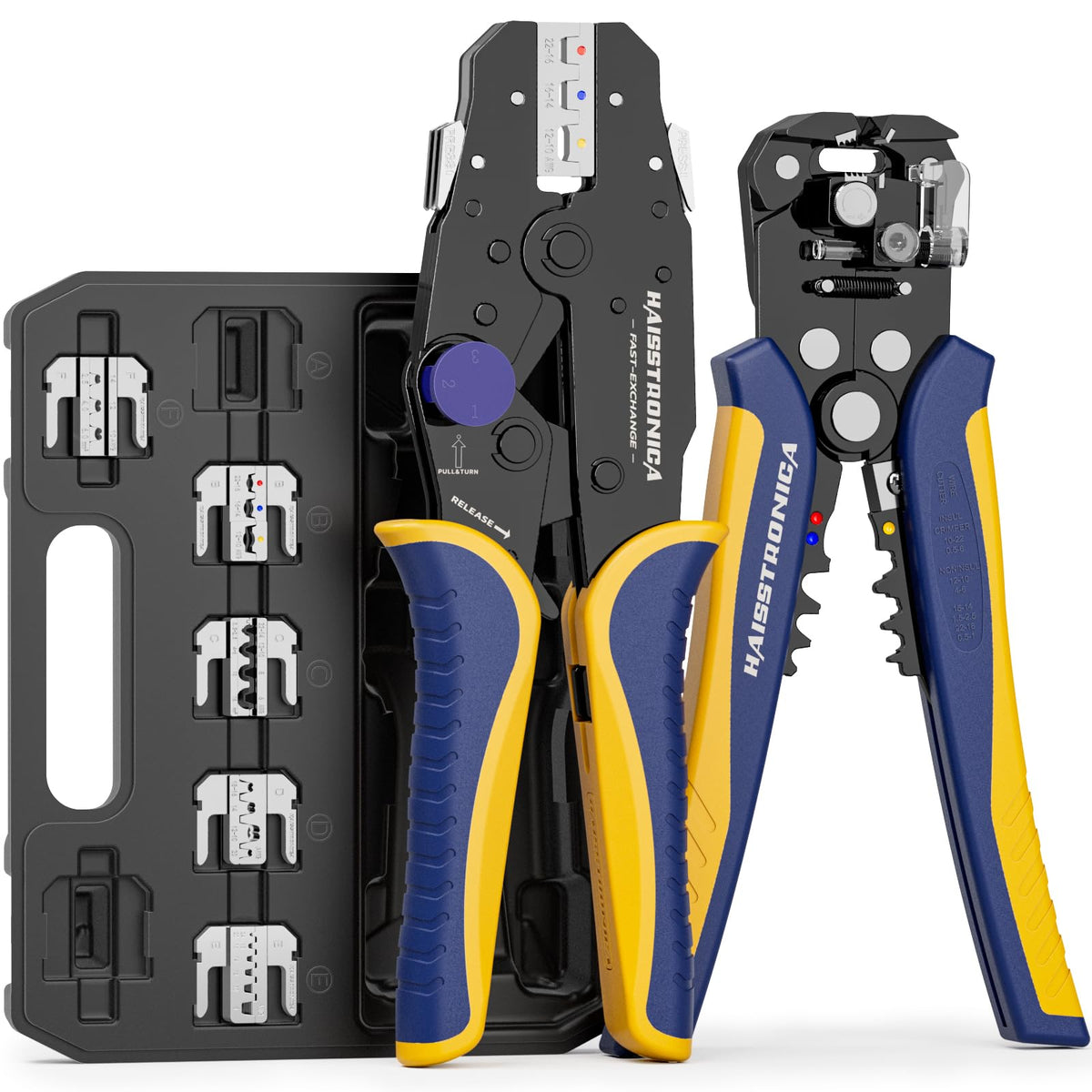
Interchangeable-die kit for multiple connector families
A 6-in-1 or 8PCS kit is useful when one technician works across several compatible connector families. The advantage is organization—not universal compatibility.
- Identify each die before the job and verify its published range.
- Seat interchangeable dies fully and lock them before crimping.
- Keep sample crimps or setup records for repeat jobs.
Quality gate
Four checks matter more than the tool's price
Even the correct crimper cannot compensate for a damaged conductor, wrong strip length or terminal outside its rated range.
Expose only the conductor length required by the barrel. No copper should remain outside the connector, and no insulation should sit beneath the conductor crimp.
Match terminal family, conductor AWG and die cavity. Similar-looking cavities can create very different compression profiles.
Check the barrel impression, seam position, conductor capture and insulation support. Reject cracks, severe flashing or distorted contacts.
Apply a firm, controlled pull appropriate to the wire and terminal. A connection that moves, slips or exposes strands must be remade.
Maintenance and calibration
Keep a good tool producing good crimps
Remove insulation fragments, adhesive and metal debris. Do not grind or reshape precision cavities.
Check fasteners, pivot movement, ratchet release and die retention. Replace damaged tools instead of forcing them through a cycle.
Use sample crimps, pull-test requirements or the connector maker's measurement method after die changes, repairs or high-volume use.
Start with the connector family
Browse a focused tool collection after AWG, terminal geometry and workload are known.
Frequently asked questions
Choosing and maintaining a crimping tool
Is a ratchet crimper always better than a manual crimper?
A ratchet improves cycle consistency, but it is only the better choice when the die profile and conductor range match the terminal. A mismatched ratchet tool still produces a bad crimp.
Can one crimper handle every connector?
No. Open-barrel contacts, ferrules, insulated terminals and battery lugs use different barrel geometries and force requirements. Interchangeable dies expand coverage but do not make one tool universal.
When do I need a hydraulic crimper?
Use a hydraulic tool when the cable and lug specification require forces beyond a suitable manual or compound-action tool. Verify die size, tool range and finished crimp requirements before use.
How often should a crimper be calibrated?
Follow the tool maker, connector maker and your quality system. High-volume or regulated work may require scheduled verification; occasional work still needs inspection after wear, damage, die changes or repair.
Safety: de-energize the circuit before work. Follow connector instructions, equipment requirements and applicable electrical, vehicle, marine, solar or industrial standards.