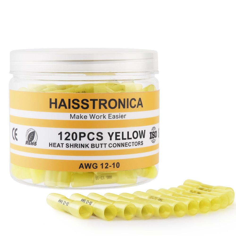

Low-temp solder rings: what melts, when it flows, and how to tell.
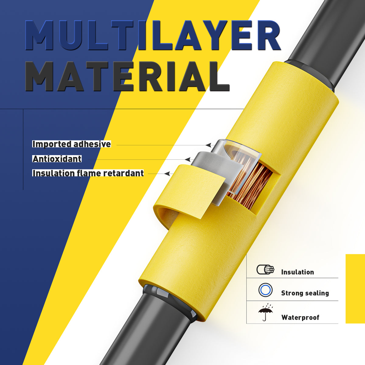
A solder-seal sleeve must do three things in sequence: shrink around the conductors, let flux clean the metal, and allow the solder ring to wet and flow through the strands without overheating the insulation.
What Is a Low-Temperature Solder Ring?
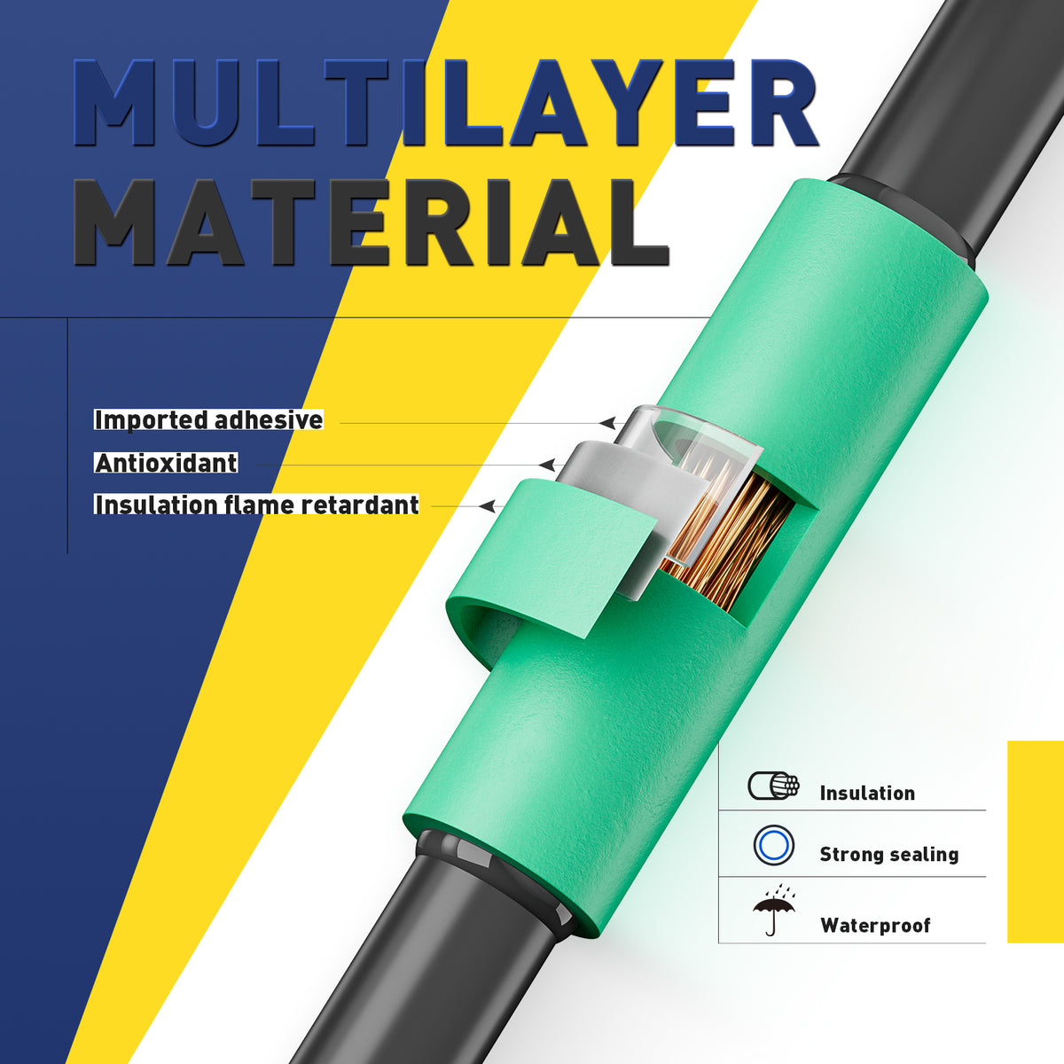
A low-temperature solder ring is a premeasured alloy band placed inside a heat-shrink connector. When heated correctly, the sleeve recovers, the flux becomes active, and the alloy softens and flows into the overlapped conductor strands. The result depends on wetting—not merely on making the ring disappear.
Low-Temp Ring vs. Ordinary Bench Solder
Both are solder alloys, but they are designed for different application methods. A connector ring is premeasured and heated through a sleeve; ordinary solder is normally fed directly into a prepared joint with a soldering iron.
| Decision factor | Low-temp solder ring | Ordinary wire solder |
|---|---|---|
| How it is applied | Prepositioned inside a heat-shrink sleeve and activated with controlled hot air. | Fed into a heated joint, usually with a soldering iron and a separate preparation process. |
| Flux delivery | Flux is integrated with or around the ring, depending on connector design. | Flux may be inside the solder core or applied separately. |
| Amount of solder | Predetermined by the connector; conductor overlap and size must match that amount. | The technician controls how much solder is added to the joint. |
| Heating method | Heat must pass through the sleeve while the joint is rotated for even recovery. | The iron transfers heat directly to the conductor and joint. |
| Best fit | Compact low-current splices where the connector and conductor ranges are compatible. | Bench work and joints designed for direct soldering with suitable strain support. |
The Correct Melting Window
First: recover the sleeve gradually
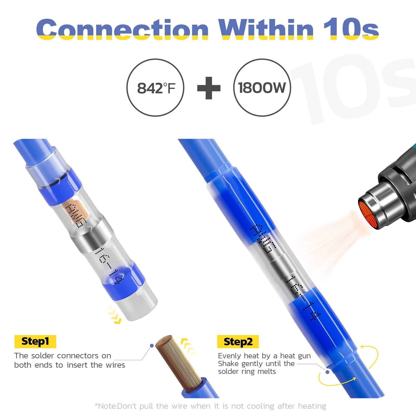
Use moderate airflow and rotate the joint. The tubing should begin shrinking evenly instead of collapsing or scorching on one side.
Then: activate flux and flow the ring
Keep the center moving through the hot-air stream. The solder ring should soften, lose its original band shape, and visibly wet into the overlapped strands.
Next: confirm the seal rings
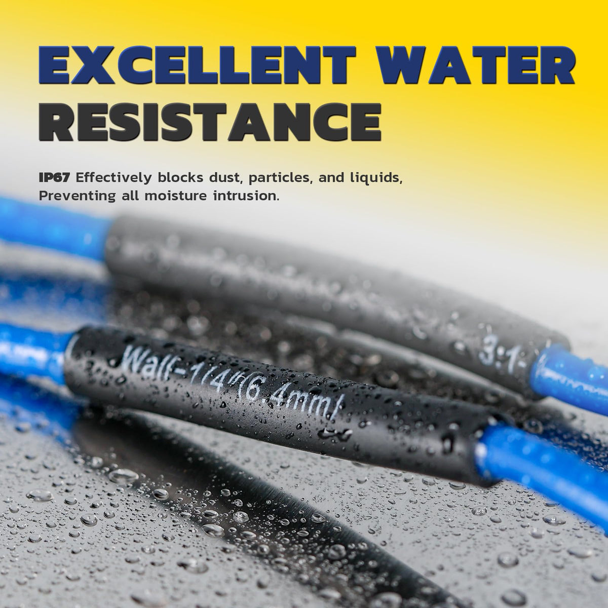
The adhesive rings near the sleeve ends should soften and form a small, even bead at the wire entry points.
Finally: cool without movement
Remove heat and hold the splice still until the alloy solidifies. Moving the conductors during cooling can disturb the joint.
Underheated, Correct, or Overheated?
The solder ring still looks like a sharp band, the alloy has not spread through the strands, or the sleeve is recovered but the center remains unchanged.
Risk: weak wetting and an intermittent electrical joint.
The original ring shape disappears, solder wets the conductor overlap, the sleeve remains clear and intact, and adhesive beads appear evenly at the ends.
Result: a sealed splice formed within the connector's intended process window.
The sleeve browns, bubbles, splits, or distorts; insulation softens; adhesive runs excessively; or the conductor jacket recedes.
Risk: damaged insulation, lost seal geometry, and reduced strain support.
Quality Checklist Before You Buy
Check the center joint
- Visible, centered solder ring
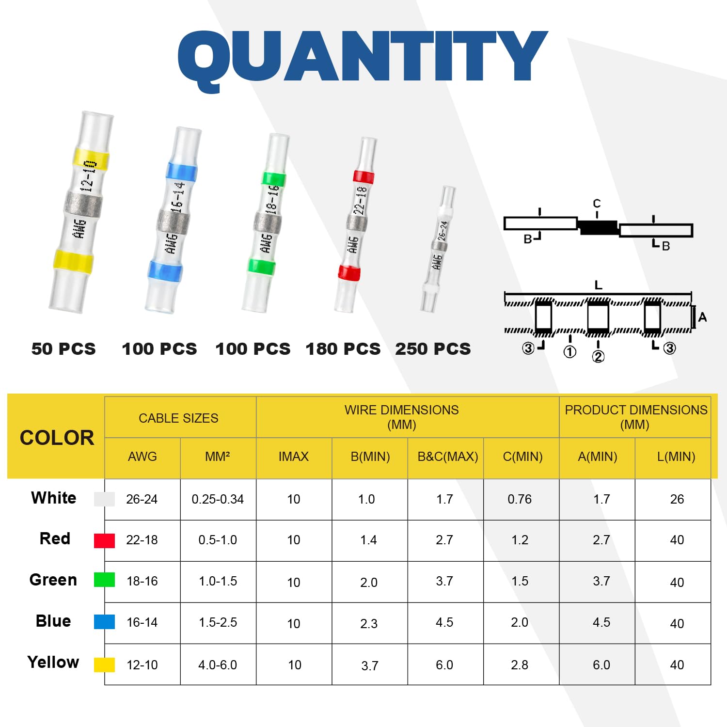
- Enough alloy for the stated conductor range
- Flux integrated with the ring or clearly specified
- Consistent ring placement from sleeve to sleeve
Check the sealing system
- Two adhesive rings positioned near the ends
- Clear tubing with consistent wall thickness
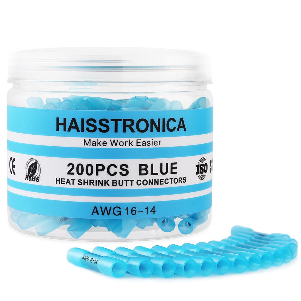
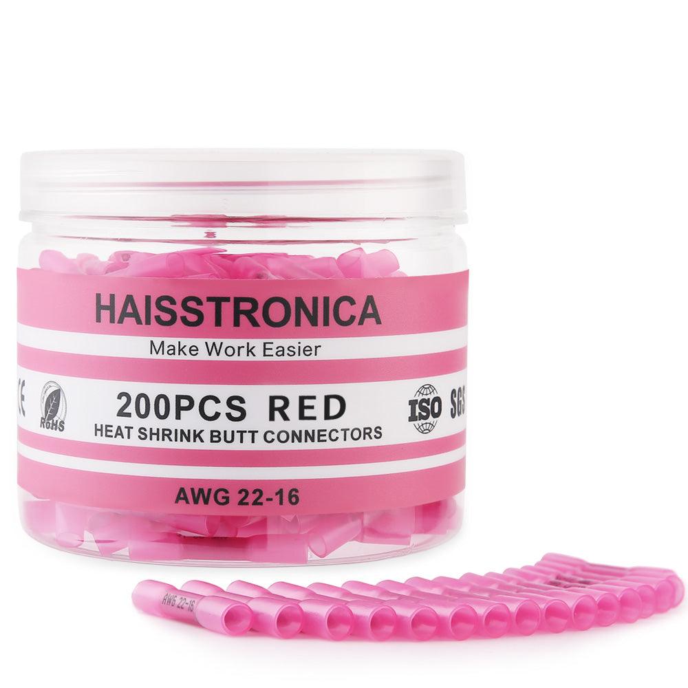
- Printed or documented AWG compatibility
- Organized sizes that prevent near-match selection

Choose a documented, organized connector kit
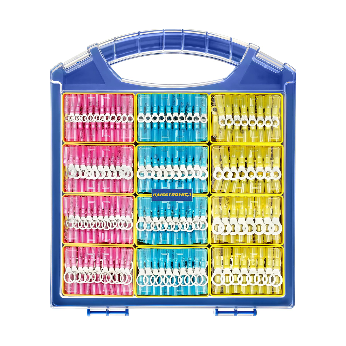
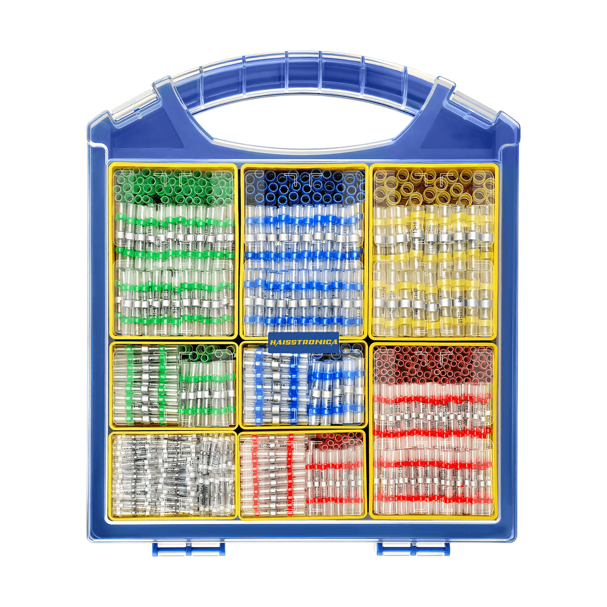
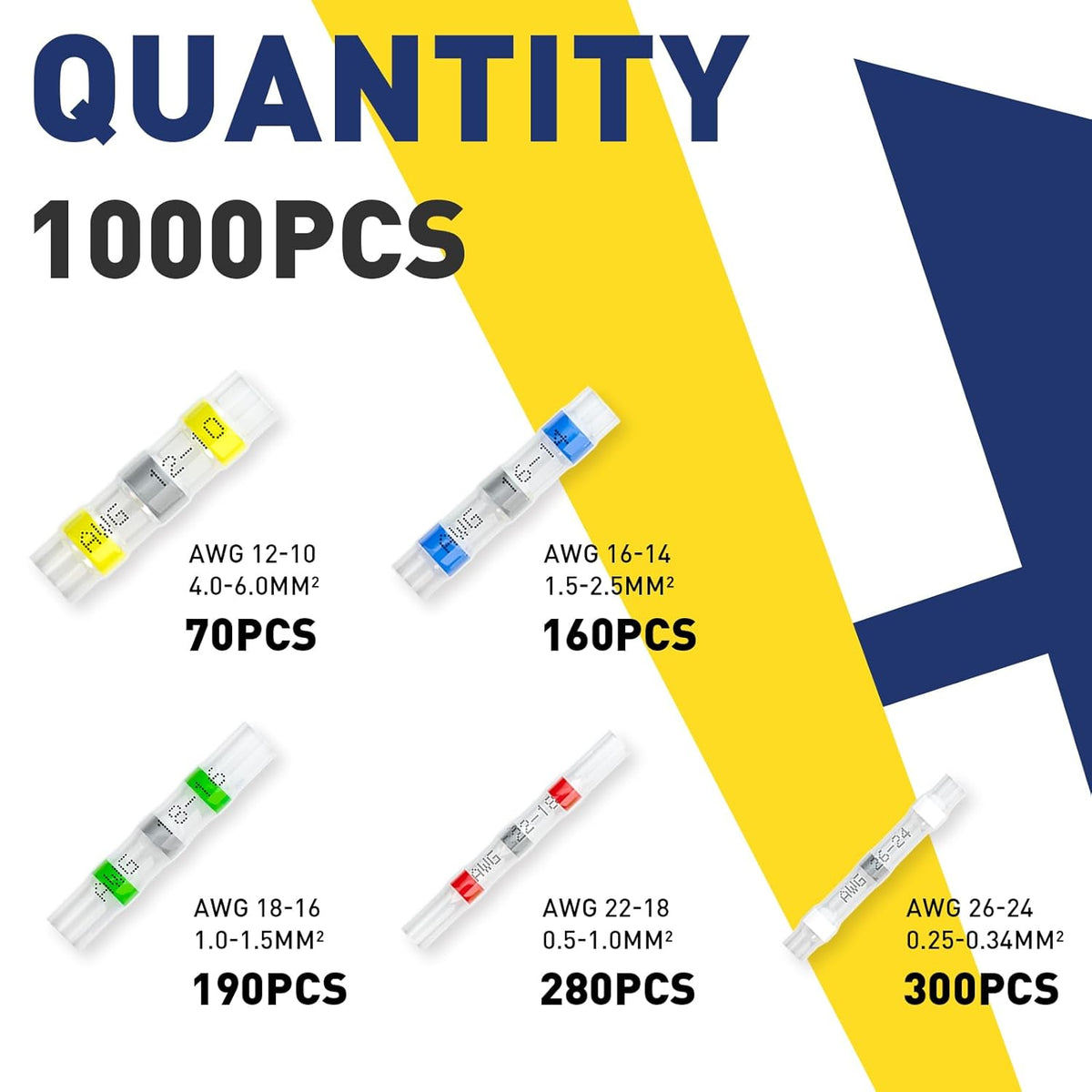
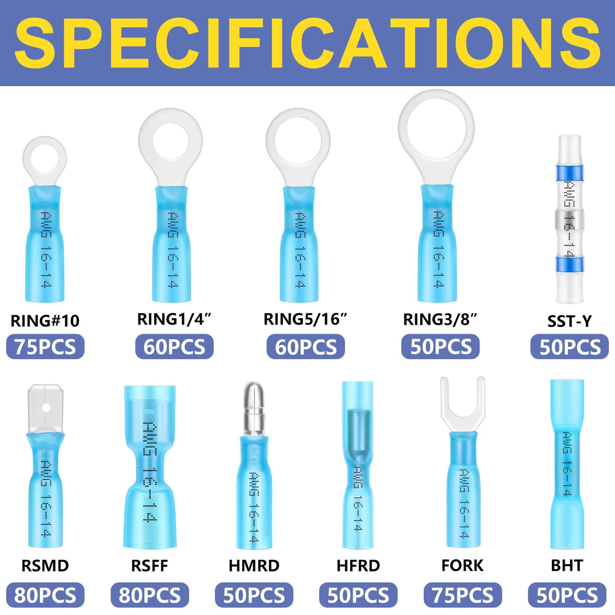
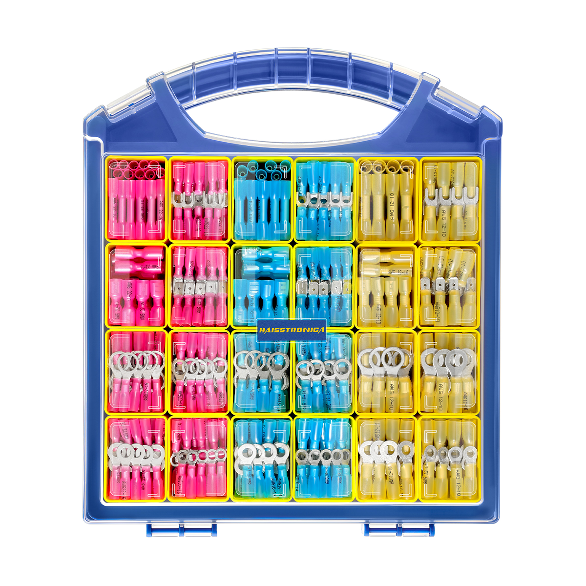
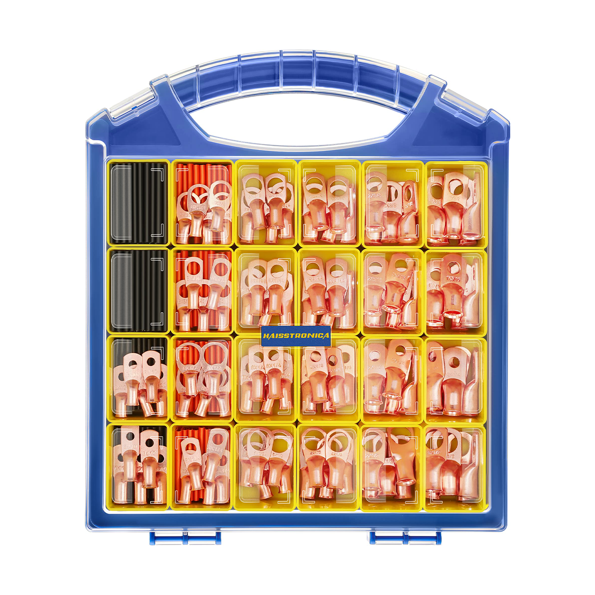
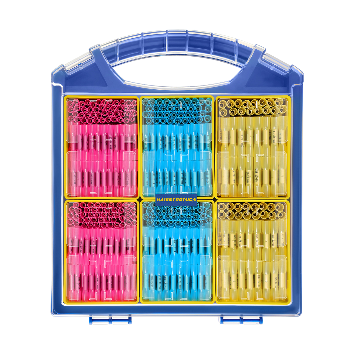
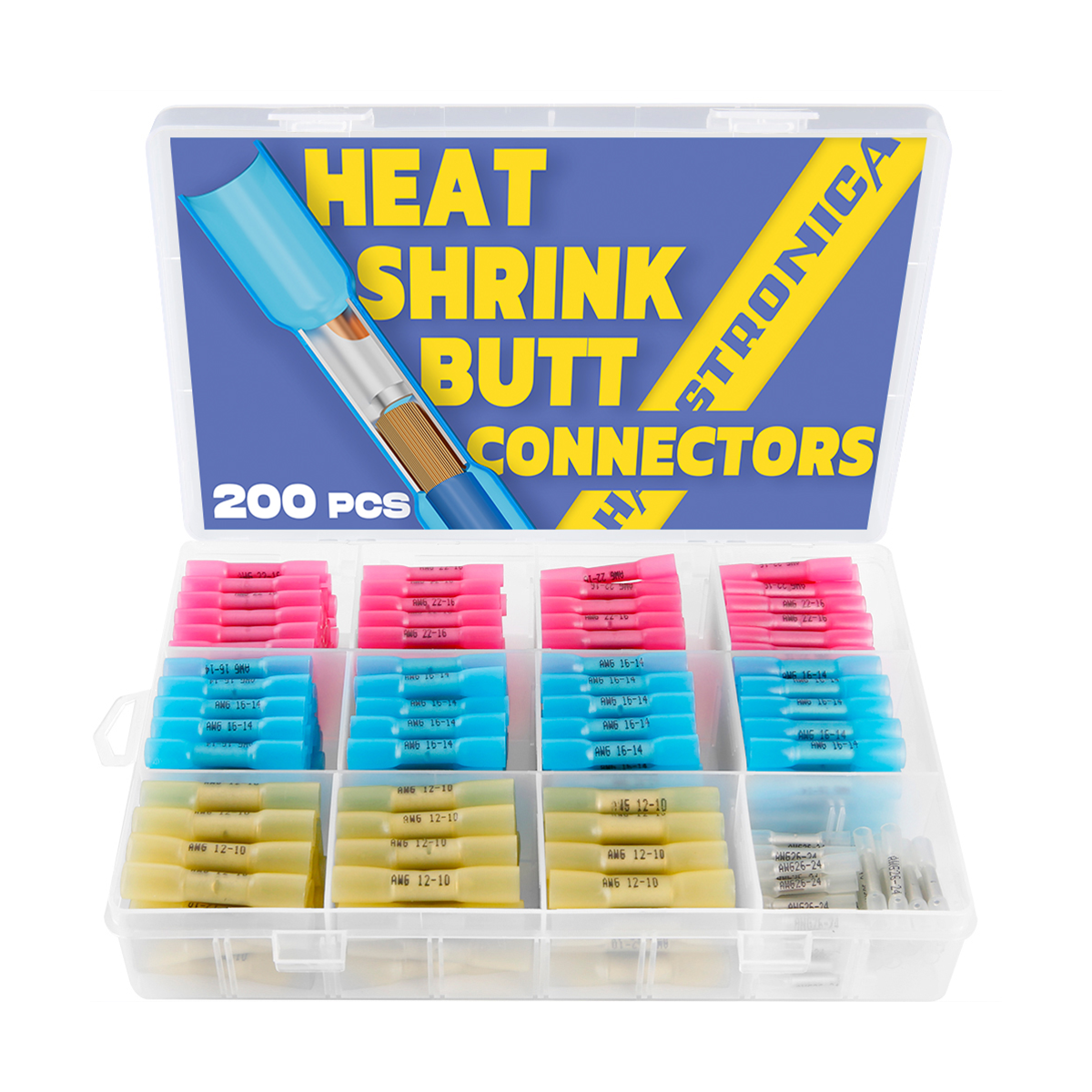
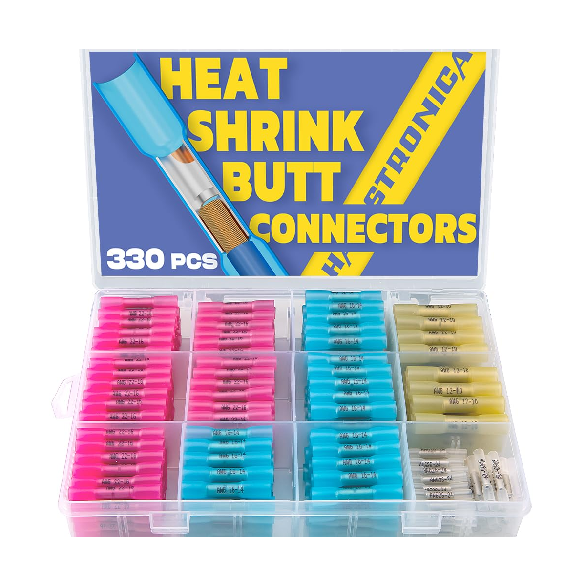
Multiple AWG ranges in separate compartments make it easier to select the correct sleeve, inspect solder-ring consistency, and avoid forcing an oversized or undersized connector onto the conductor.
Shop Premium Solder Seal Kit →Control the Heat Source
The goal is not maximum temperature. The goal is stable hot air, continuous movement, and enough time for the joint—not only the tubing surface—to reach the alloy's flow window.
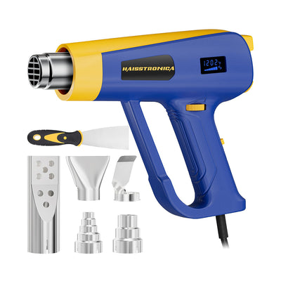
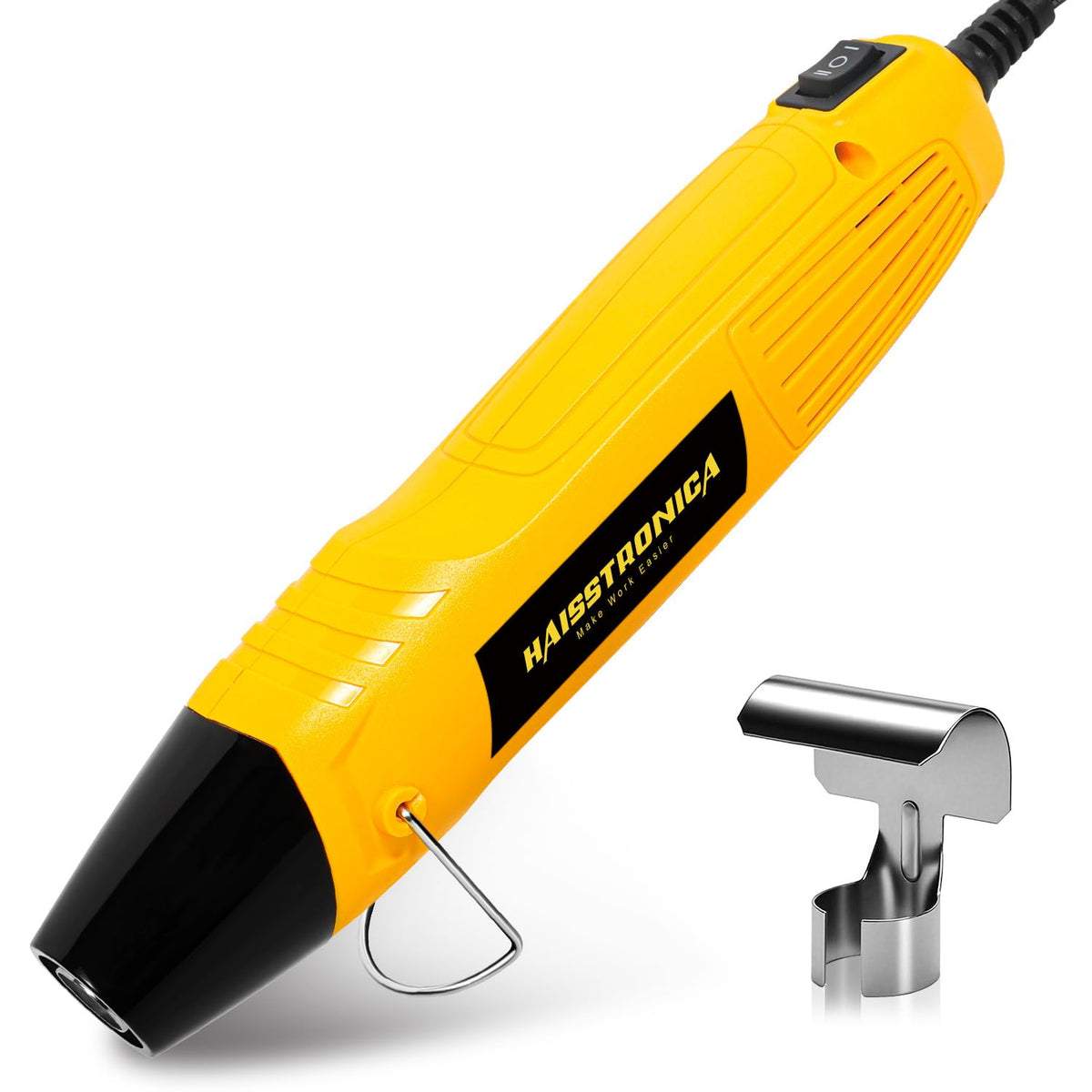
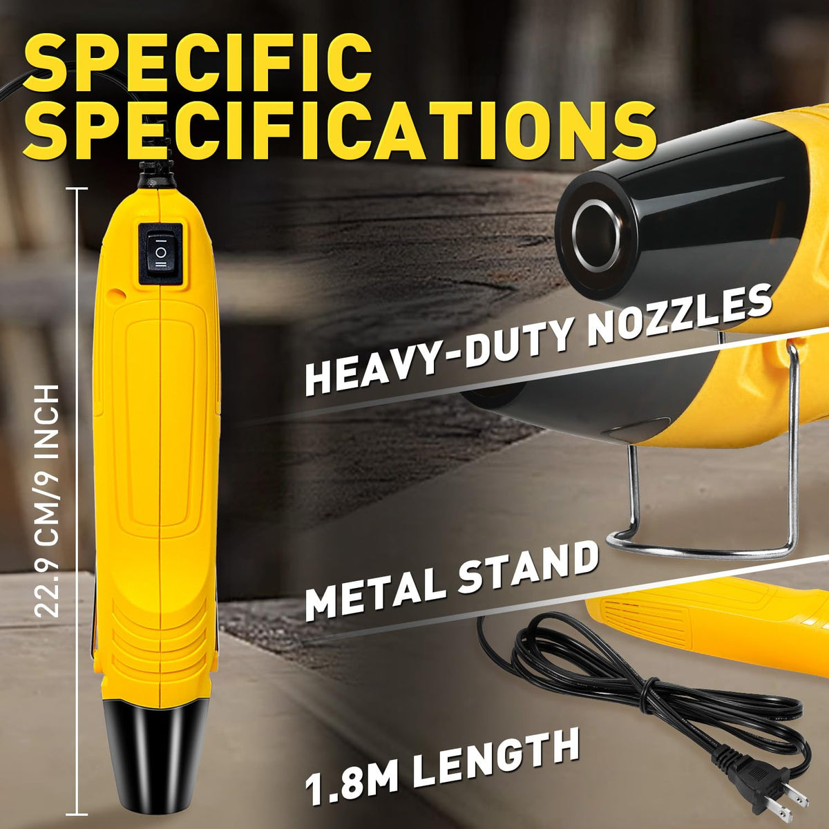
Adjustable Heat Gun
Use adjustable output when the connector, conductor mass, or ambient conditions require finer control. Begin conservatively and increase only as needed.
Shop Adjustable Heat Gun →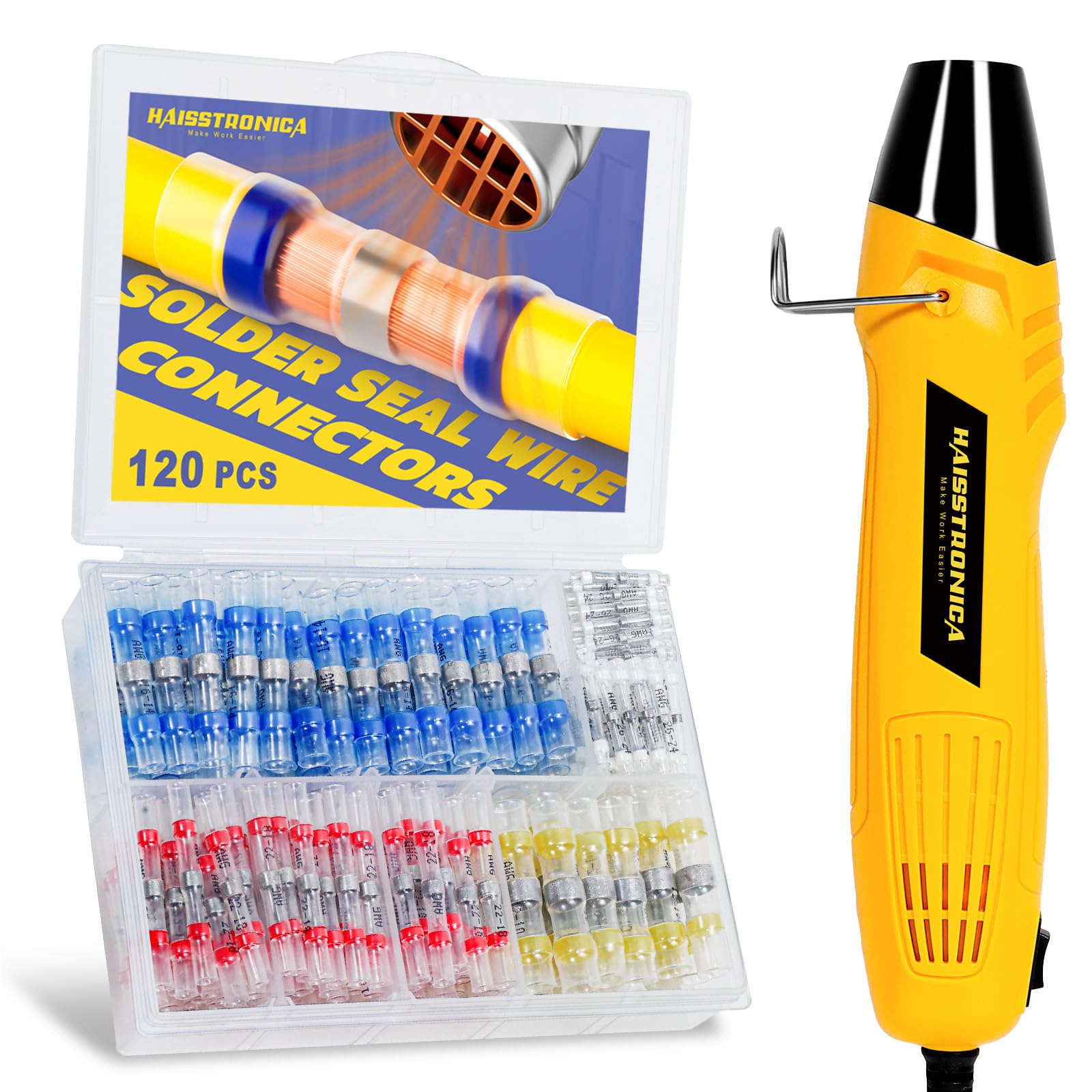
Heat Gun + Solder Seal Kit
A matched starter route keeps the heat source and compatible connector sizes together for repeatable installation and storage.
Shop Heat Gun Kit →Heat a Solder-Seal Connector in Seven Steps
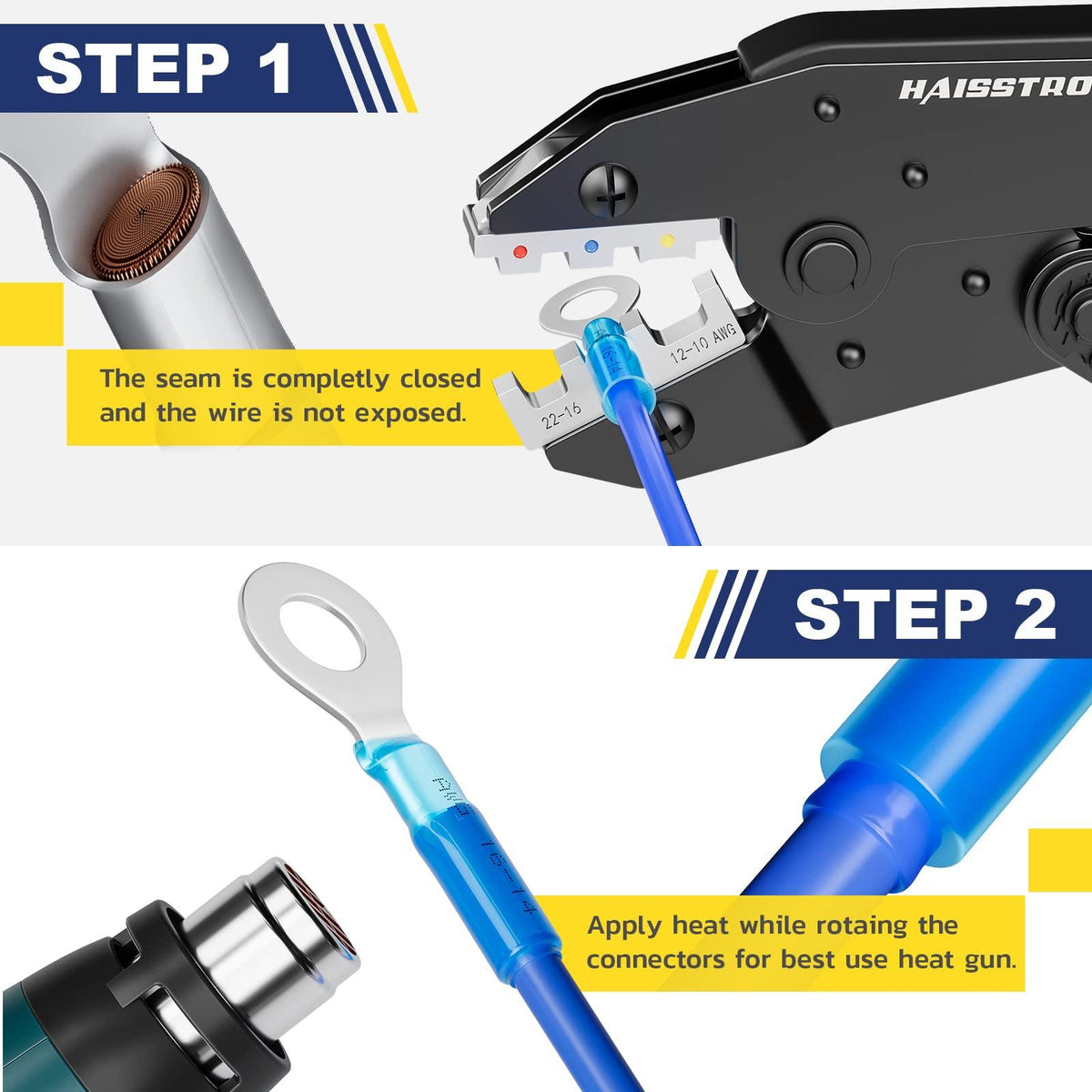
Confirm the conductor range
Read the wire marking and choose the sleeve designed for that conductor size and material.
Strip without cutting strands
Expose the length needed for the conductors to overlap beneath the center solder ring.
Center the overlap
Place the bare conductor overlap directly beneath the solder ring, with insulation under the end sealing zones.
Begin with controlled heat
Rotate the splice and sweep the hot air. Do not park the nozzle against one side of the sleeve.
Watch the solder flow
Continue until the ring loses its band shape and visibly wets into the conductor overlap.
Confirm the adhesive seal
Look for small, even adhesive beads at both ends without excessive runoff or scorched tubing.
Cool, inspect, and support
Hold the conductors still while cooling, then inspect clarity, wetting, end seals, and strain support.
Final Buying Checklist: Solder, Flux, and Seal Rings
1. Solder amount
Choose a sleeve whose ring mass and AWG range match the conductor overlap. A large sleeve on a small wire is not an upgrade.
Compare Connector Sizes →2. Flux information
Look for a connector that explains how flux is integrated and provides clear heating and wetting guidance.
Browse Solder Seal Collection →3. Adhesive rings
Verify two end-seal rings, consistent placement, and tubing that stays clear enough to inspect the finished joint.
Shop the All-in-One Set →Buy the sleeve as a complete joining system.
The alloy, flux, tubing, adhesive rings, conductor range, and heat source must work together. Choose by documented AWG compatibility and visible construction quality, then install by watching solder wetting—not by heating for a fixed number of seconds.