


Straight vs Angled Battery Cable Lugs: Choosing for Tight Spaces
Straight or angled? Start with the installed cable route.
When comparing straight vs angled battery cable lugs, choose a straight lug when its cable exit follows the available route without forcing a bend. Consider a factory-made 90° lug when its barrel direction better matches the installation. Neither shape is automatically lower, stronger, or more suitable: check the installed geometry and the cable–lug–tool combination before ordering. See the manufacturer’s angled-lug reference.
Where must the cable leave the connection?
Will the cover close and the socket fit?
Do the cable, lug, and approved tooling match?
Picture an auxiliary battery beneath a shallow cover, with its cable running toward a nearby fuse block. The important question is not “Which lug looks compact?” It is “Where will the barrel, insulated cable, terminal cover, and tightening tool actually fit?”

View straight-lug specifications and variants →
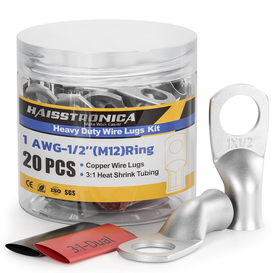
Start with Haisstronica’s cable-gauge and stud-hole options. This is a straight-lug candidate, not a verified 90° product listing.
1. Choose the Shape Around the Connection
The palm is the flat portion bolted to the connection; the barrel receives the conductor. For conventional tubular lugs, a straight configuration runs approximately parallel to the palm’s contact plane. A bent-palm 90° configuration changes that relationship. Read the drawing rather than interpreting “right angle” as a guaranteed cable direction in the vehicle. BURNDY terminal reference.
Use this table as a planning guide, not an approval for a specific installation.
| Task or restriction | Shape to consider | Check before deciding |
|---|---|---|
| Cable can leave along the mounting plane | Straight | Barrel length, cable bend, and nearby obstacles |
| Horizontal contact surface beneath a shallow lid | Straight first | A raised 90° barrel may use more vertical space |
| Cable must leave perpendicular to a vertical contact surface | Factory-made 90° | Projection into the compartment and cover clearance |
| A wall blocks the proposed cable route | Compare both | Whether the alternative moves the cable into genuinely usable space |
| Closely spaced studs or recessed hardware | Neither wins automatically | Palm width, hole position, socket access, and insulation |
| Cable needs regular removal or inspection | Either, if serviceable | Access with covers and neighboring components installed |
These are geometric decision rules. They do not establish a universal clearance allowance or replace the equipment manufacturer’s installation requirements.
Choose the terminal first
Haisstronica’s tinned-copper lug page offers conductor-size and stud-hole selections. It describes a bottle containing ten same-size lugs and ten adhesive-lined heat-shrink sleeves—not twenty lugs. This format is worth checking when several terminations need the same specification. Confirm barrel dimensions, conductor-class suitability, and the permitted crimping method before purchase.
View straight-lug specifications and variants →
Need 90 degree battery cable lugs?
A verified Haisstronica 90° lug listing was not located for this guide. Ask support to confirm a suitable part, supplying the cable specification, stud size, and top and side views of the installation. Request a dimensional drawing and tooling requirements. Do not assume a straight-lug assortment contains angled terminals.
Supporting tool—not a substitute for the terminal
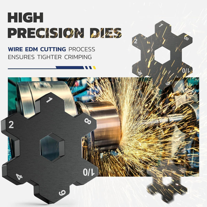
The Haisstronica battery-cable crimper kit is a candidate installation tool. Its published rotating-hex-die sizes are 8, 6, 4, 2, 1, and 1/0 AWG. It uses non-ratcheting lever compression. Those markings do not confirm compatibility with every straight or angled lug, and they do not cover 2/0–4/0 AWG.
2. Compare the Specifications That Determine Fit
Two terminals can accept the same nominal wire size yet differ in stud opening, barrel construction, and installed footprint. Keep electrical compatibility separate from physical fit. Panduit terminal documentation.
| Specification | What to establish |
|---|---|
| Cable AWG or mm² | Documented conductor size—not the outside insulation diameter |
| Conductor material and strand class | The exact construction accepted by the lug manufacturer |
| Barrel dimensions | Internal diameter, insertion depth, wall thickness, and approved conductor fit |
| Stud-hole size | Compatibility with the equipment’s specified stud or bolt |
| External geometry | Palm width and thickness, barrel length, bend height, and installed projection |
| Tool and die requirements | Approved profile, die identification, crimp locations, and inspection criteria |
Manufacturers publish these as separate selections. For example, Panduit’s LCAX-F documentation identifies supported conductor classes and die references independently of stud-hole size. This illustrates the checking process; it does not approve Panduit terminals for a Haisstronica tool.
AWG, millimeters, and stud holes are different measurements
A marking such as “2 AWG × 5/16 in.” describes conductor size and stud-hole selection—not the lug’s overall dimensions. A metric conductor cross-section is not a hole diameter, and an approximate AWG conversion is not permission to substitute a terminal rating. Keep the cable’s original specification and the lug manufacturer’s supported sizes together.
For right angle copper cable lugs, also request a side-view drawing. Overall length alone cannot tell you whether the barrel fits under a lid. Record the actual obstruction in the relevant direction, then compare the complete assembly, including insulation and hardware.
Do not estimate missing dimensions from a product photograph. Ask for a drawing or measure the exact unenergized sample before committing to the layout.
Select the correct tool-kit variant
The published kit configurations differ. Assortment quantities depend on the selected variant. Do not transfer a photo’s contents to another option.
| Variant | Listed configuration |
|---|---|
| HX1771 | Crimper, cutter, and lug/heat-shrink assortment |
| HX2052 | Crimper, cutter, and carrying case |
| HX2053 | Crimper, cutter, assortment, and carrying case |
A right-angle palm must also leave enough access for the approved die to work on the barrel. Successful placement between the jaws is only a physical check; it is not proof that the resulting crimp meets the terminal’s requirements.
3. Check the Layout Before Cutting Cable
The following is a planning sequence, not a substitute for the vehicle’s service procedure.
Isolate the system before taking measurements
Follow the vehicle and accessory manufacturers’ isolation instructions, including auxiliary batteries and charging sources. Verify that the intended work area is safe before handling conductors. Keep exposed live connections protected, remove conductive jewelry, and use appropriate eye protection and insulated tools. CCOHS cautions against metal objects bridging battery terminals and against excessive twisting forces on the posts. High-voltage hybrid and EV traction systems are outside this guide. CCOHS battery safety guidance.
Inspect from above and from the side
Record the mounting surface, stud location, cable route, and nearby obstacles in both views. Include the battery hold-down, enclosure wall, fuse-block cover, and the space needed to remove the terminal cover later.
A layout that appears clear from above can still fail under the lid. Conversely, a part that looks tall on a bench may fit an installation where that dimension points into an open compartment. Rotate the drawing into the installed orientation before comparing shapes. Use a nonconductive template for clearance checks; never bridge battery terminals with a metal ruler.
Plan the cable’s bend and end orientation
Use the cable manufacturer’s bend-radius requirement for the actual cable and service conditions. There is no single radius supplied by the words “battery cable.” Tricab, for example, lists minimum bend radius and cable outside diameter separately by cable size. Do not borrow another cable’s value merely because its AWG matches. Tricab cable specifications.
Also plan clocking: the rotational orientation of the lug relative to the cable and its opposite end. Battery Cables USA treats terminal rotation and a 90° bent-lug option as separate assembly choices. Specify both ends before fabrication rather than twisting a completed cable to force the palms onto their connections. Battery Cables USA assembly FAQs.

View straight-lug specifications and variants →
Include the cover, socket, and support
Check the terminal boot or enclosure cover in its closed position. Leave room for the specified tightening tool and for supporting the cable without using the lug as a routing lever.
The palm must seat as the equipment manufacturer specifies. Victron’s bolted-connection guidance, for example, requires direct seating against the mounting surface and warns against putting a washer between that surface and the lug. Follow your equipment’s own hardware order and torque; do not import one universal arrangement into every vehicle. Victron DC wiring guidance.
Confirm fabrication and inspection requirements
Before crimping, obtain the conductor preparation, die, crimp-position, and inspection instructions for the chosen combination. Plan any boot or sleeve that must go onto the cable before termination.
After assembly, inspect the connection and perform the checks required by the applicable instructions. A firm hand pull is not a calibrated tensile test, and a neat-looking crimp does not establish electrical performance. Haisstronica’s battery-lug installation guide covers the workflow separately, so this comparison need not repeat it.
Die markings identify size positions, not universal approval.
View the battery-cable crimper kit →
Recognize Layouts That Still Fail
The following are illustrative planning examples, not customer cases or measured tests.
- The 90° lug hits the cover. On a horizontal mounting surface, a conventional upward barrel may occupy space that a straight lug would leave clear. Recheck the side view; “angled” does not mean “low profile.”
- The nut fits, but the socket does not. A nearby barrel, wall, or adjacent terminal can obstruct tightening access. Include the tool’s working space in the layout, not just the hardware’s final position.
- The cable reaches only when twisted. Revisit cable length and lug clocking. Do not force the installed cable to compensate for an unsuitable end orientation. Terminal rotation options.
- The connection fits only without its protective cover. Treat that as a failed layout, not a successful space-saving modification. Reassess the connector, route, or approved mounting arrangement.
- The required cable exceeds the available tool’s range. Select appropriate tooling; do not reduce the electrically required cable size or remove strands to make the parts fit. Cable selection and terminal preparation must remain within their documented requirements.
This guide does not claim measured space savings, lower temperature, improved pull strength, or faster installation for either shape. Those comparisons require identified samples and a documented test method.
4. Finish the Selection Without Creating a New Problem
Conditions that require another decision
Pause when the lug’s conductor-class rating is missing, the hardware cannot seat correctly, the cover cannot close, or the required tooling is unidentified. A damaged stud, evidence of overheating, or an unexplained existing failure also needs investigation before choosing a replacement shape. Seek qualified help when safe isolation or suitability cannot be established.
Do not cut strands, drill a larger stud hole, or reshape a straight terminal to imitate a factory-made angled one. Select a documented part rather than treating machining, bending, or heating as an undocumented compatibility fix.
Does a 90° lug carry more current?
Angle alone provides no such assurance. Compare the specific terminal’s ratings, compatible conductor, connection requirements, and operating conditions. Do not infer higher current capacity or lower resistance from a compact appearance.
Can one cable have a straight lug at one end and an angled lug at the other?
Potentially, when each end matches its connection and the completed assembly meets the installation requirements. Specify each end’s conductor fit, stud hole, geometry, and clocking independently. A mixed-shape assembly is a layout choice, not automatic approval for a particular vehicle.
What else belongs in the project?
Project essentials: correctly specified terminals and tooling, the equipment’s required connection hardware, appropriate insulation or covers, and cable support.
Condition-dependent items: suitably sized adhesive-lined heat shrink, abrasion protection, and pass-through protection where required by the route and environment. Tubing over the barrel does not replace a cover over an exposed stud or palm.
Optional convenience: a carrying case or organizer. Neither changes electrical compatibility. Verify accessory dimensions before adding them to the order; this guide does not establish a specific terminal-boot fit.
Confirm the fit. Then choose the installation kit.
For battery cable lugs for tight spaces, choose the shape that works in the actual installed orientation—with the cable, covers, hardware, and tools included. Confirm the termination combination next. Only then choose the installation kit.
Before ordering, send cable size and construction, stud specification, installation photos, available space, and the proposed lug and tool. Request the missing specifications before selecting a variant.
Send details for compatibility review →Related guides
- Conductor selection: Cable lugs for fine-stranded wire
- Fabrication: Battery-lug crimping workflow
- Existing connection problems: Battery-cable voltage-drop diagnosis


