BATTERY CABLE / DIAGNOSTIC GUIDE
Battery Cable Voltage Drop Test: How to Find Hidden Connection Problems

Why Voltage Drop Testing Finds Problems You Cannot See
A battery cable voltage drop test can find resistance that a visual inspection misses. Instead of checking a cable at rest, you measure the voltage lost across that cable or connection while current is flowing. On a conventional 12-volt starting circuit, that usually means measuring during cranking. A high reading tells you that part of the path is consuming more voltage than it should. Fluke recommends testing voltage drop with current flowing because static resistance measurements may not reveal restrictions that appear under operating load.
The key is to test the positive cable and ground path separately, then narrow an excessive reading to the battery post-to-clamp interface, a cable or crimped lug, or another bolted connection. Do not use one universal pass/fail number for every vehicle or battery-powered system. Vehicle-specific procedures can use different test conditions and different limits, so the vehicle or equipment manufacturer’s service information should take priority.
This guide is for conventional low-voltage battery and starting circuits. It is not a procedure for hybrid or EV high-voltage traction systems.
A cable can look clean outside and still have excessive resistance inside a corroded connection, under a battery clamp, at a ground connection, or within a damaged cable. Voltage drop testing is effective because it checks the circuit while it is actually doing work.
The electrical principle is straightforward:
Voltage drop = Current × Resistance
In a starter circuit, high current makes unwanted resistance easier to detect as voltage loss. This is why slow cranking or an overheating connection may appear even when a cable still passes a basic continuity check. Fluke notes that a multimeter's low-current resistance test can miss restrictions that become significant when the real circuit is loaded.
A voltage drop test also helps prevent unnecessary parts replacement. If the positive-side reading is excessive, the problem might be at the battery terminal, inside the cable assembly, at a crimped lug, at an intermediate junction, or at the starter connection. Testing smaller sections helps identify where most of the loss occurs.
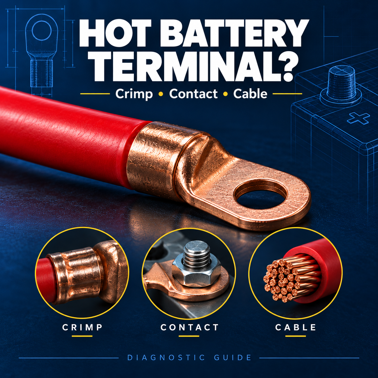
If heat is your main symptom, use Haisstronica’s related guide on how to diagnose a battery cable terminal that is getting hot. That article focuses on distinguishing crimp, contact-surface, and cable-sizing problems; this guide focuses on the voltage-drop test itself.
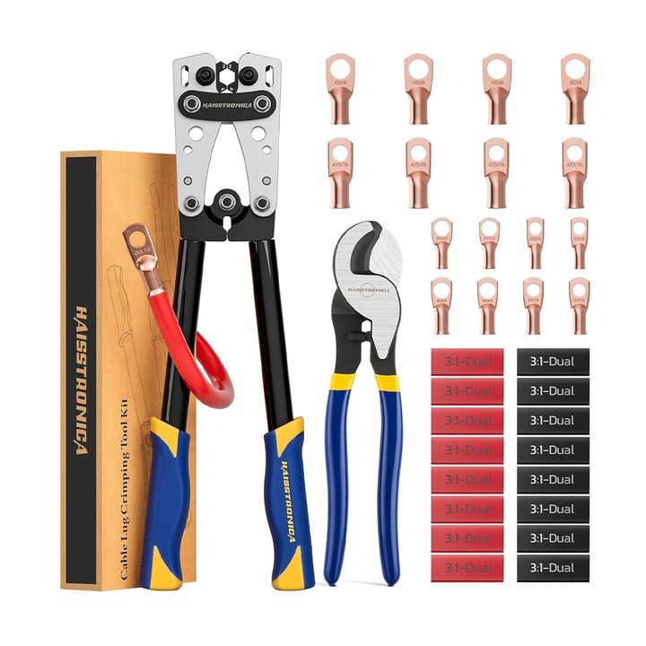
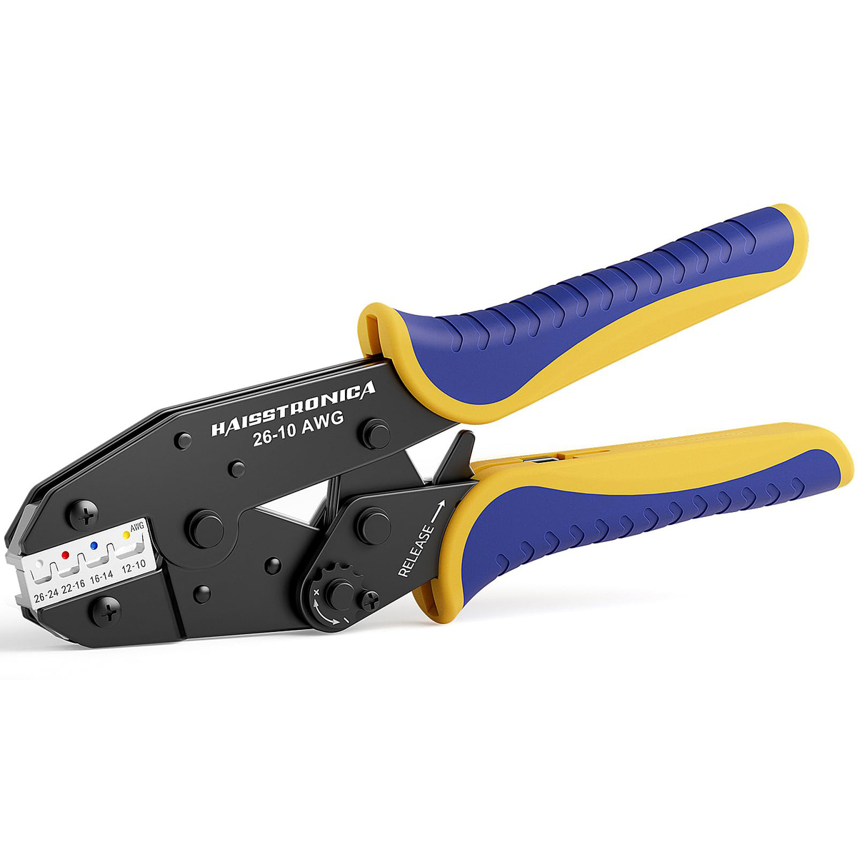
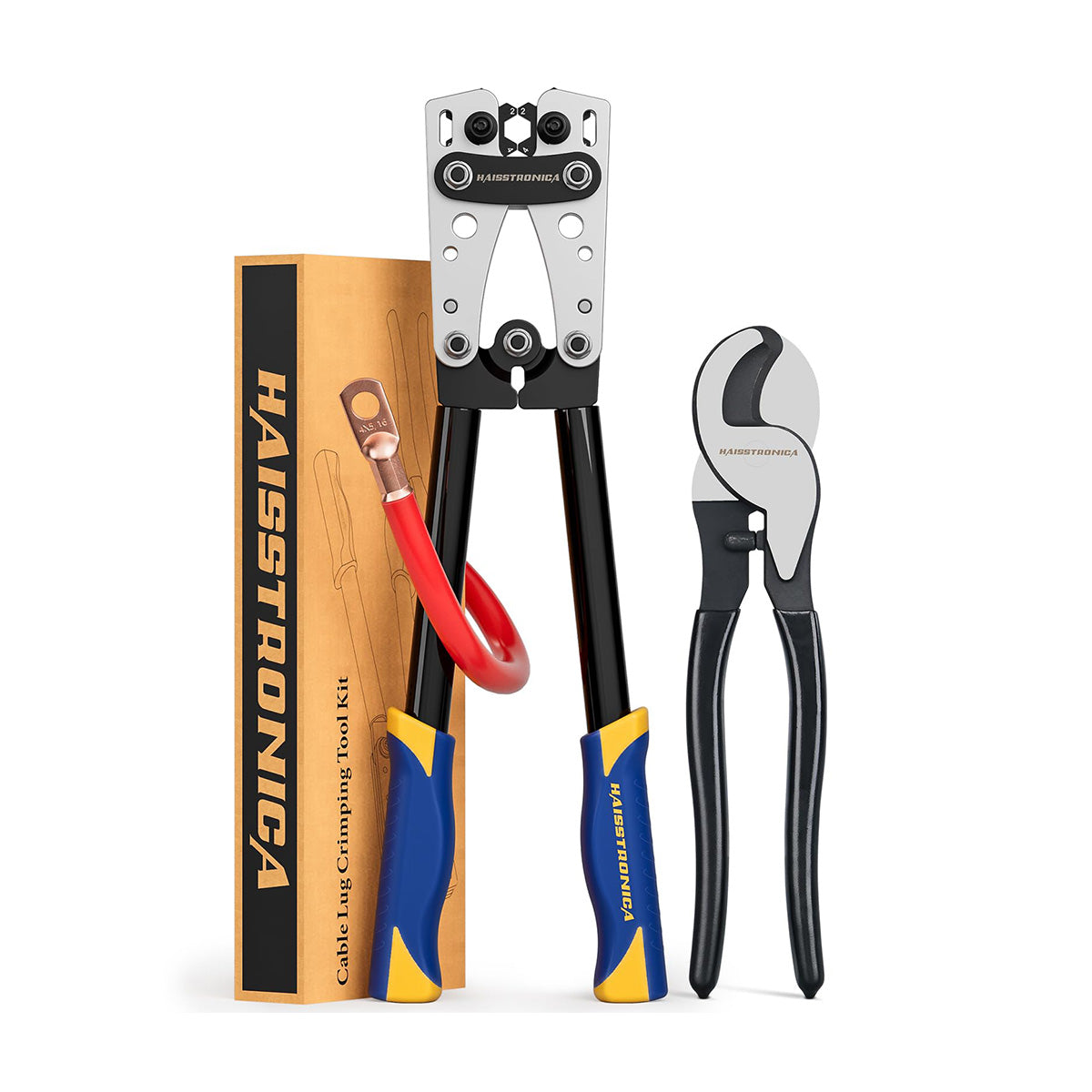
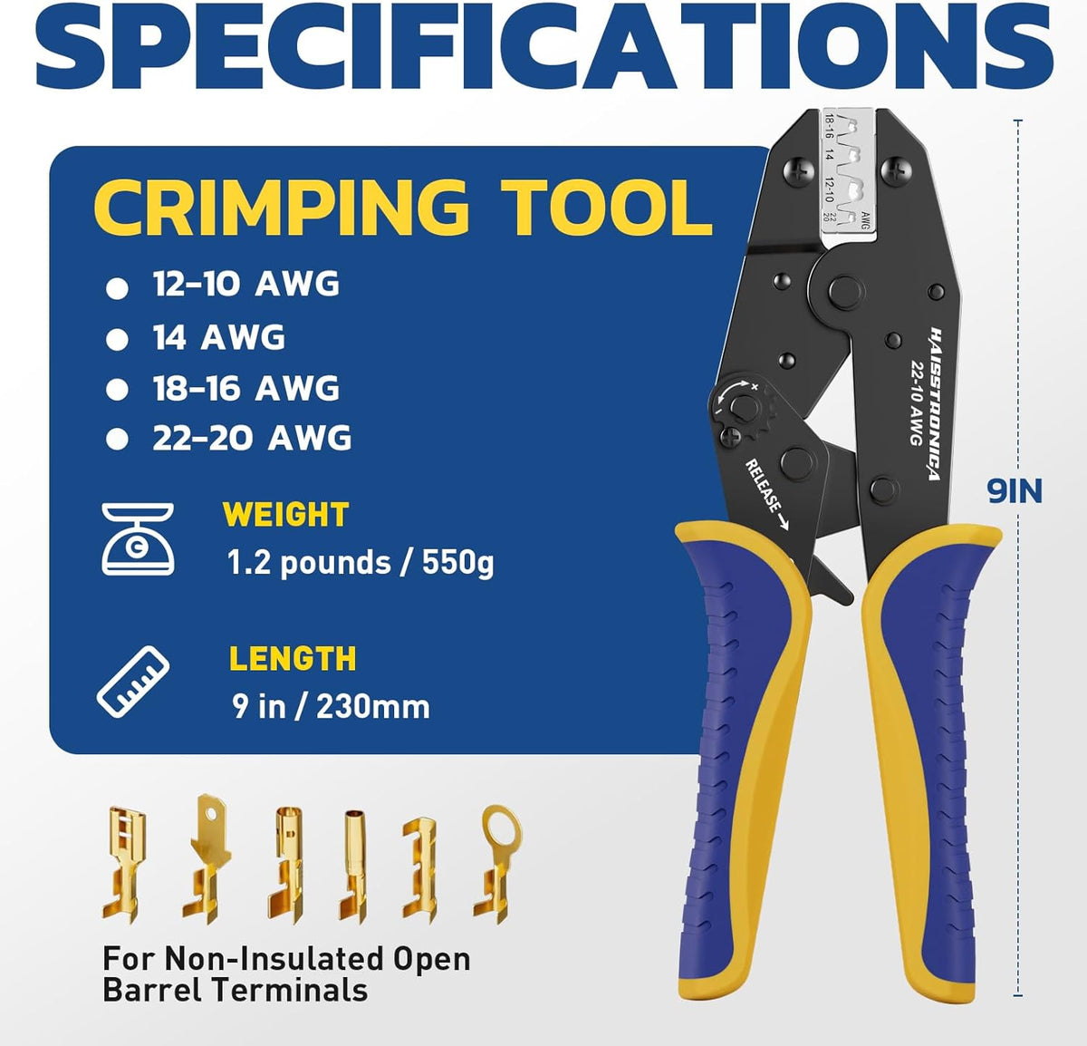
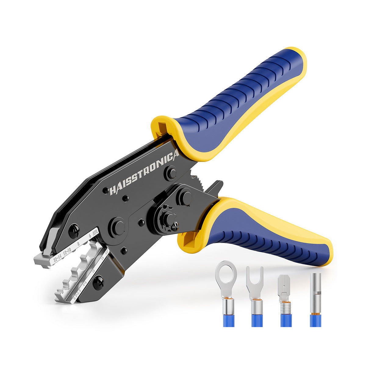
Haisstronica Battery Cable Lug Crimping Tool Kit AWG 8–1/0
Diagnose the high-resistance section before replacing a lug. If a replacement termination is needed, review this rotating-hex-die crimper kit and confirm the cable, lug and die are compatible.
Check Tool Compatibility →Before You Test: Safety, Meter Setup, and Test Conditions
Use a digital multimeter capable of reading DC volts and millivolts, with intact insulated test leads. Fluke’s starter-circuit procedure calls for DC-voltage measurement and describes using a low-voltage or millivolt range when appropriate.
Follow the battery and vehicle manufacturer’s safety instructions before testing. For flooded lead-acid batteries, Trojan Battery advises wearing protective clothing, gloves, and eye protection; keeping flames, sparks, and metal objects away; and avoiding accidental short circuits.
For a starter-circuit test:
- Put the vehicle in Park or Neutral and apply the parking brake.
- Keep hands, clothing, probes, and meter leads clear of moving components.
- Avoid bridging battery or starter terminals with a probe.
- If the test requires cranking without allowing the engine to start, disable fuel or ignition only according to the applicable vehicle service procedure.
Cranking duration is another reason not to invent one universal procedure. DENSO’s starter diagnostic instructions say not to crank for more than 10 seconds at a time and to wait at least 60 seconds before cranking again. Fluke’s example uses a shorter 4- to 5-second crank. Follow the procedure for the vehicle you are servicing.
Set the multimeter to DC volts. A millivolt range or autoranging can make small losses easier to read. Use capture features such as MIN/MAX only when the applicable vehicle procedure permits them; the required measurement method takes priority.
Before diagnosing the cables, make sure the battery itself is adequately charged and serviceable. DENSO puts battery load testing, charging-system confirmation, and cable inspection ahead of its voltage-drop diagnosis.
How to Run the Positive and Ground Cable Tests
Whole circuit → Positive side / Ground side → Individual connection → Confirm fault → Repair → Retest
A voltage-drop test places the meter across the section you want to test.
You are not measuring battery voltage from positive to negative. You are measuring the difference between two points on the same current path while that circuit is carrying load. Fluke describes this as connecting the DMM across a wire, cable, connection, or other circuit section to directly measure the voltage lost across it.
Positive Battery Cable Voltage Drop Test
For a conventional starter circuit, Fluke’s procedure uses:
Red probe → battery positive post
Black probe → starter motor battery/B+ stud
Then crank the engine for the duration permitted by the applicable test procedure and observe the reading.
This positive battery cable voltage drop test measures the combined loss between those two test points. Depending on the vehicle, that path may include the battery post-to-clamp interface, cable conductor, cable terminations, junctions, and the starter-terminal connection.
If the reading is excessive, do not immediately conclude that the cable itself is defective.
Instead, divide the positive path into smaller sections.
For example, perform the loaded test from:
Battery positive post → battery cable clamp
That isolates the voltage drop across the battery terminal interface. If most of the total positive-side loss appears across this very small connection, the post-to-clamp interface deserves attention before the cable or crimp is replaced.
Next, move one probe to the next accessible electrical node and repeat the test under comparable load. Work progressively toward the starter until you isolate the section responsible for the excessive loss. Fluke recommends simplifying a circuit into smaller sections when tracking a restriction.
Do not pierce cable insulation merely to create a measurement point unless the applicable manufacturer procedure specifically instructs you to do so.
Battery Ground Cable Voltage Drop Test
The ground side uses the same principle.
In Fluke’s starter-circuit example:
Red probe → battery negative post
Black probe → starter housing or engine block
With this lead orientation, a negative reading may appear during cranking. Compare the magnitude of the drop, not the minus sign, with the applicable limit. DENSO shows the opposite ground-side lead polarity (red on the starter housing and black on the battery negative post) for a positive reading. Crank under the same controlled conditions and record the result.
An excessive battery ground cable voltage drop test result can point toward the negative battery terminal, negative cable assembly, engine or chassis ground connection, ground strap, or a poor mounting/contact surface. DENSO likewise recommends separating positive- and negative-side testing when the complete circuit shows excessive loss.
You can continue narrowing the ground side by measuring across one accessible connection at a time, for example:
Negative battery post → negative cable clamp
Then:
Negative cable connection → engine or chassis ground point
And, where applicable:
Engine block → starter housing or another ground interface
Use accessible, clean metal test points appropriate to the vehicle.
Probe position matters. Measuring between the battery post and its clamp examines that specific interface. Moving both probes farther downstream could exclude that interface and therefore hide its contribution to the overall loss.
Try to keep test conditions comparable. Voltage drop changes with current, so readings taken under substantially different battery state, temperature, cranking speed, or load are not directly equivalent.

Haisstronica Battery Cable Lug Crimping Tool Kit AWG 8–1/0
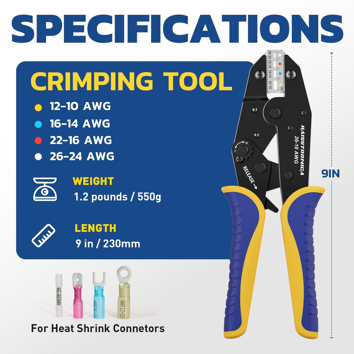
The marked hex dies support AWG 8, 6, 4, 2, 1 and 1/0 for compatible battery cable lugs. Match the conductor, lug barrel and required crimp profile before choosing a die.
View Crimper Specifications →How to Interpret the Reading and Decide What to Repair
There is no single voltage-drop limit that should be applied to every vehicle, starter, cable length, and test method.
Use OEM service information whenever it is available.
As a general starter-circuit reference, Fluke gives approximately 0.3 V for the positive side and 0.2 V or less for the ground side, with approximately 0.2–0.5 V total in its example.
DENSO’s starter troubleshooting procedure uses 0.5 V as the maximum overall system loss in its example before proceeding to positive- and negative-side isolation.
That difference is exactly why the better diagnostic question is often:
Where is most of the voltage being lost?
| Test section | What the reading includes | If drop is excessive |
|---|---|---|
| Battery positive post → starter B+ stud | Complete positive starting path | Isolate terminal, cable, crimps, junctions, starter connection |
| Battery negative post → starter housing / engine block | Main ground-return path | Isolate negative terminal, cable, grounds and straps |
| Battery post → battery clamp | One battery-terminal contact interface | Inspect looseness, contamination, corrosion, damage and applicable hardware |
| Across one accessible bolted lug interface | One mechanical/electrical contact | Check mating surfaces, hardware and specified tightening procedure |
| Accessible end → end of a cable assembly | Cable plus its terminations | Investigate conductor or termination problems |
Suppose the complete positive path has an excessive reading, but nearly all of that loss is found between the battery post and clamp. In that case, investigate the terminal interface before cutting off a crimped lug.
If the post-to-clamp drop is low but the cable assembly accounts for most of the loss, internal conductor damage or a bad battery cable crimp becomes more plausible.
That is still a diagnostic conclusion, not proof of the physical failure mode. A voltage-drop test identifies where electrical resistance is occurring. Determine the physical cause after the circuit has been safely de-energized.
Rebuild a Cable Only After the Test Points to the Connection
Once the high-resistance section has been identified, disconnect and isolate power according to the battery, vehicle, or equipment manufacturer’s procedure before cleaning, tightening, or replacing components.
Use the specified hardware and tightening procedure for the actual battery terminal, starter stud, busbar, or ground point. Do not copy a torque value from another vehicle. If testing points to a crimped battery-lug assembly, cable gauge alone does not prove that a replacement lug and crimper are compatible.
Confirm separately:
Cable: AWG or mm², conductor material, and strand construction.
Lug: conductor/barrel size, barrel material and wall geometry, and stud-hole size.
Crimper: supported conductor range, die size, and required crimp profile.
Installation: insulation/sealing method, mechanical mounting, and the applicable inspection or qualification procedure.
“Fits inside the lug” and “the tool can squeeze it” are not compatibility specifications.
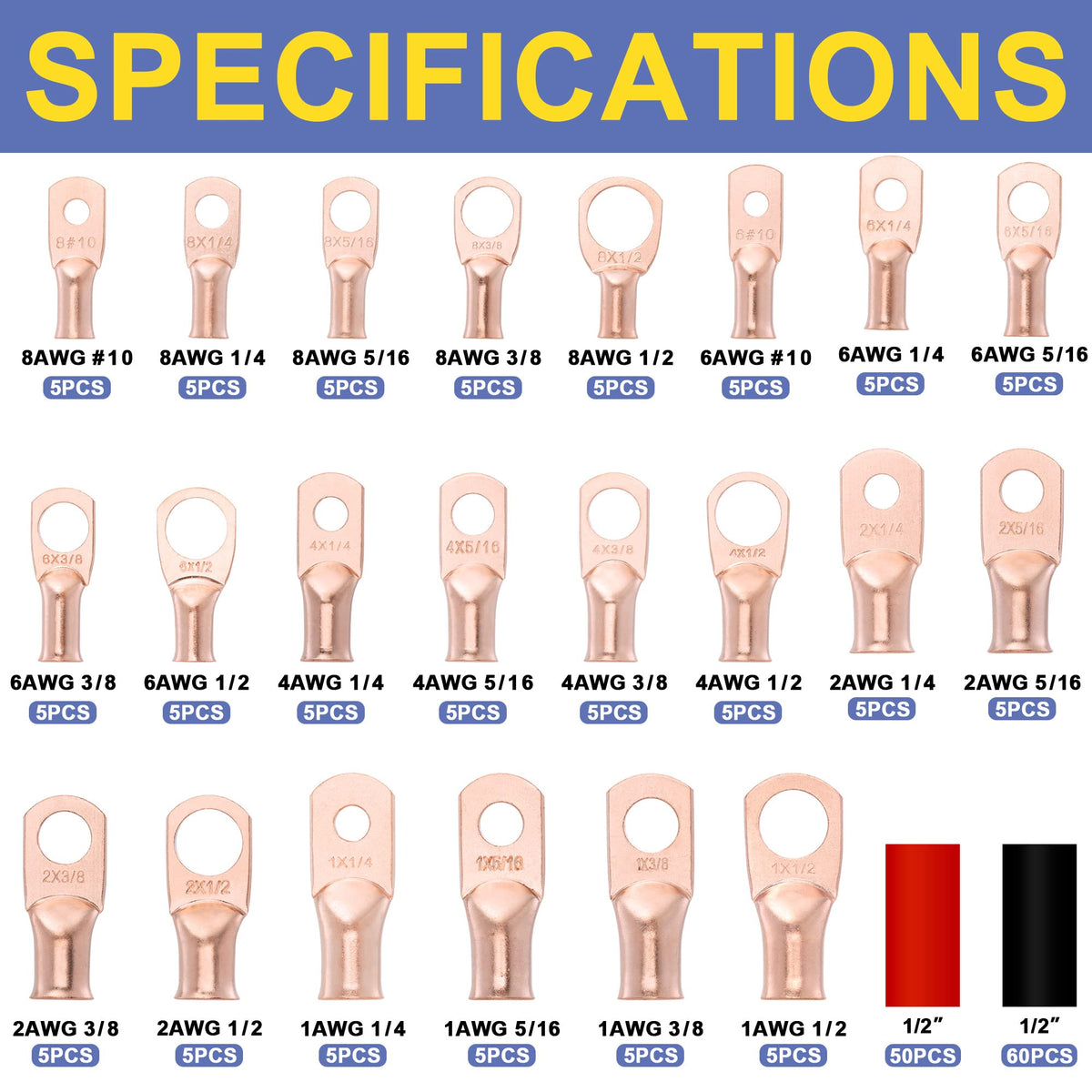
For owners of the Haisstronica Battery Cable Lug Crimping Tool Kit AWG 8–1/0, the current detailed product specification lists rotating hex dies for AWG 8, 6, 4, 2, 1, and 1/0 and a non-ratcheting lever-compression mechanism. Haisstronica also states that conductor size, lug barrel material/wall thickness, and required crimp profile must match the selected die. The product page specifically excludes 2/0 and 4/0 cable and terminals requiring a different crimp profile.
That means the voltage-drop test should come before cutting off a lug. It helps answer an important question:
Is the crimp actually the problem?
If the faulty termination is confirmed and the replacement cable/lug combination falls within the tool’s published compatibility range, follow the actual product and lug requirements rather than choosing the die simply because the cable fits.
For rebuilding technique, continue with Haisstronica’s guide to crimping heavy wire lugs. For broader diagnosis, see Troubleshooting Bad Crimps: How to Test, Diagnose & Fix a Poor Connection. The current product page itself also instructs users to verify cable gauge, lug barrel and stud size, select the appropriate marked hex die, fully insert the conductor, complete the compression, inspect the termination, and perform a pull check.
After repair, repeat the same loaded voltage-drop test, at the same test points and under comparable conditions.
That before-and-after electrical comparison is more informative than judging the connection by appearance alone. A manual pull check can reveal an obviously loose termination, but it should not be presented as a formal pull-force qualification or as proof that the electrical connection meets an applicable specification.
The practical workflow is:
Test the whole path under load → isolate positive or ground → divide the failing path into smaller sections → identify the actual connection → repair it → retest.
That is how a battery cable voltage drop test finds connection faults that can remain invisible until high current makes them matter.
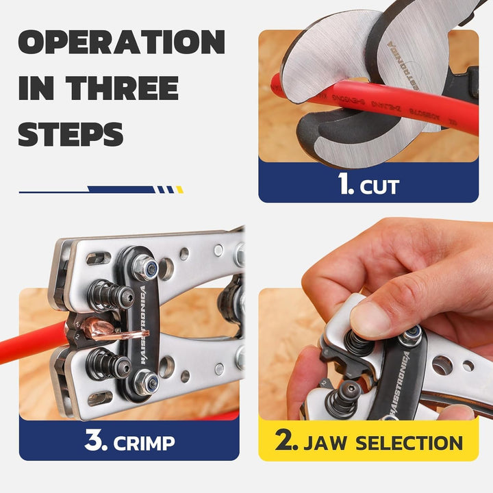
Haisstronica Battery Cable Lug Crimping Tool Kit AWG 8–1/0
Once testing confirms a faulty termination, check the kit specifications before rebuilding. Kit accessories vary by option; the tool is not for 2/0 or 4/0 cable.
Explore the Crimper Kit →