
Plan the run. Size the wire. Seal every connection.
Start with distance and fixture load—not a default roll of 12/2. Compare 14/2, 12/2, and 10/2 copper landscape wire, then turn your route into a cable-and-connector checklist.

Distance × load → preliminary wire choice
Use this for one transformer circuit or zone with one wire gauge throughout. Enter the farthest actual cable path and the total connected load. For AC LEDs, use nameplate VA or watts divided by documented power factor; watts alone can understate current.
Fixture limits and cable allowance
Fixture connections and spare connectors
Count each location once. The estimate assumes a separate sealed connector for each of the two insulated conductors; a proprietary two-pole connector system needs a different count.
Example inputs are shown. Check your fixture limits, connection counts, and cable paths, then calculate. This is a voltage-drop screening tool—not an electrical design approval or an ampacity check.
Calculation method, assumptions, and limits
The planner places the full circuit load at the farthest fixture, a conservative layout simplification. Design current = load VA (or DC watts) ÷ entered minimum fixture voltage. Estimated drop = 2 × one-way feet × design current × conductor resistance ÷ 1,000. AC watts are converted using the documented power factor.
Generic copper reference resistances are 2.631, 1.662, and 1.040 Ω/1,000 ft for 14, 12, and 10 AWG; this planner applies a 25% resistance margin. These are not measured Haisstronica cable specifications. Connector losses, driver behavior, inrush, temperature extremes, and transformer regulation require separate checks. The planner stops above 10 A design current; that is its modeling limit, not a cable or transformer rating.
A candidate must satisfy the entered fixture voltage limits. Independently verify cable ampacity, fuse/breaker protection, transformer total VA, each output circuit rating, connector wire combinations, and product listings. For multiple independent circuits, calculate each separately. Confirm near- and far-end voltages with all lights operating.
References: Kichler load and voltage-drop guidance · Southwire copper resistance reference.
1. Plan the fixtures, power source, and load
Sketch each fixture, transformer, main run, and branch. Label the load and cable distance of every zone. Keep lights out of mower paths and route cable away from sharp edges, roots, heat, and areas likely to be disturbed.
Choose a compatible lighting system
Match fixture input voltage and AC/DC requirements to the landscape power supply. Add the actual fixture load, allowing the headroom required by the equipment manufacturer. A larger transformer does not automatically cure voltage drop on a long cable.
Set up power safely
Use the required outdoor, weather-protected GFCI receptacle and follow the transformer's mounting and clearance instructions. Keep the supply disconnected while assembling connections. New mains wiring, an unsuitable outlet, pool/spa installations, or uncertain code requirements need a qualified electrician.
Original installation video retained. Follow the instructions for your actual cable, fixtures, connectors, and transformer where details differ.
2. Choose the calculated gauge, then the roll length
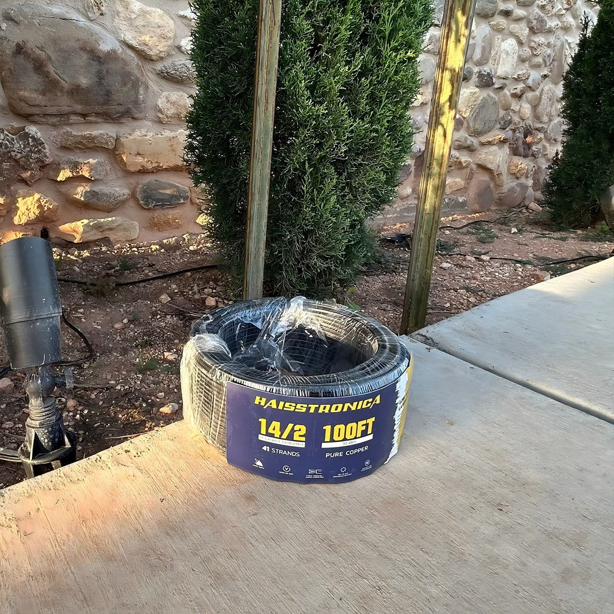
The first number is the conductor gauge; “/2” means two conductors. Lower AWG numbers mean thicker conductors. Electrical run length and total purchase length are different measurements—do not use the spool size as a voltage-drop limit.
14/2 · Only when the calculation supports it
A lower-load, shorter path may fit 14/2. Check voltage drop and all component ratings first. If the result calls for 12/2 or 10/2, buying 14/2 simply because it is available is not an equivalent choice.
Supply note: the former 14/2 product link was unavailable when checked on August 28, 2026. Confirm an exact 14/2 replacement and the required roll length before ordering.
Browse Landscape Wire Collection →12/2 · A candidate, not the automatic default

Compare 12/2 when 14/2 falls below your voltage requirement. Choose enough cable for the measured routes and reserve, while keeping planned continuous runs intact.
Listed roll sizes: 100, 200, 250, and 500 ft. The page was marked sold out on August 28, 2026; recheck the exact option.
10/2 · Lower resistance for a demanding run
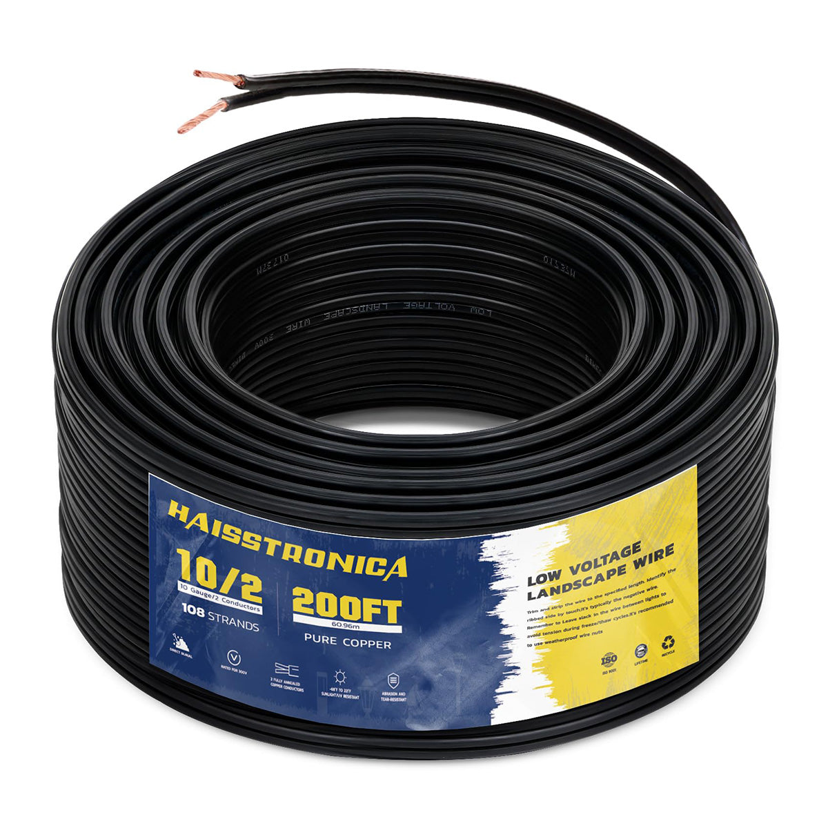
If 12/2 does not meet the voltage target, compare 10/2. If even 10/2 fails, shorten or split the circuit, reduce the load, or have the layout redesigned. Do not force a purchase result.
Listed roll sizes: 100, 200, and 250 ft. The product was listed as sold out when checked; confirm current supply before committing to the layout.
Do not downsize to match stock. The Landscape Wire collection is a browsing route, not permission to substitute 16/2 for a calculated 14/2, 12/2, or 10/2 requirement.
3. Dry-lay the main and label each branch
Measure along the actual cable path, not a straight line across the yard. Lay the cable and fixtures out before digging. Include controlled service slack at equipment and junctions, avoid tight bends, and label branches so later troubleshooting does not require opening every splice.
Simple branch plan: transformer → main run → approved branch junction → fixture branches. Fixtures are connected in parallel according to the system instructions, not as a chain that sends current through one lamp to reach the next.
Record every required continuous cable length. A total of 300 ft spread across branches is not the same as one uninterrupted 300 ft run.
4. Match the connector to the actual joint
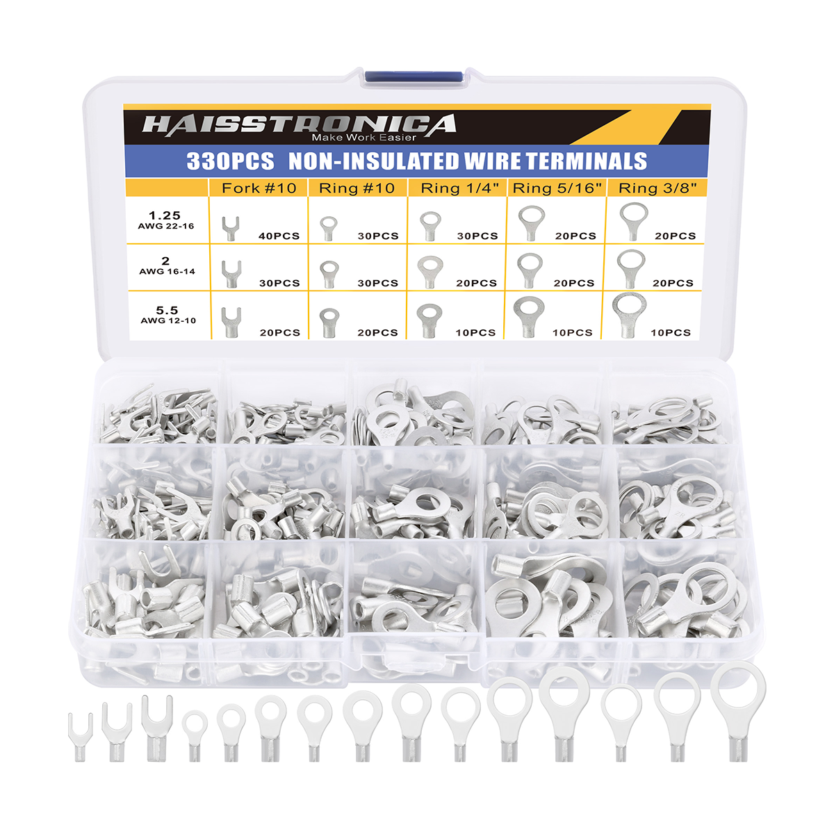
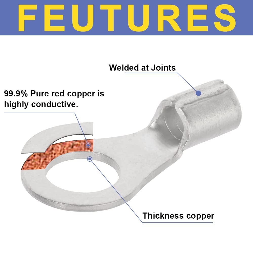
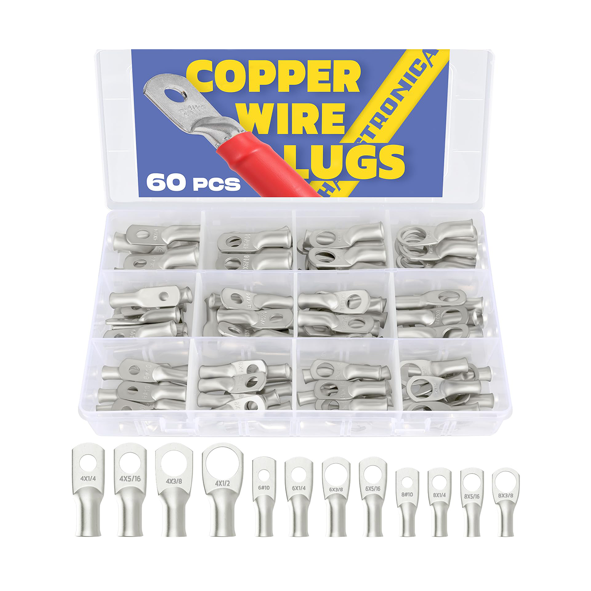
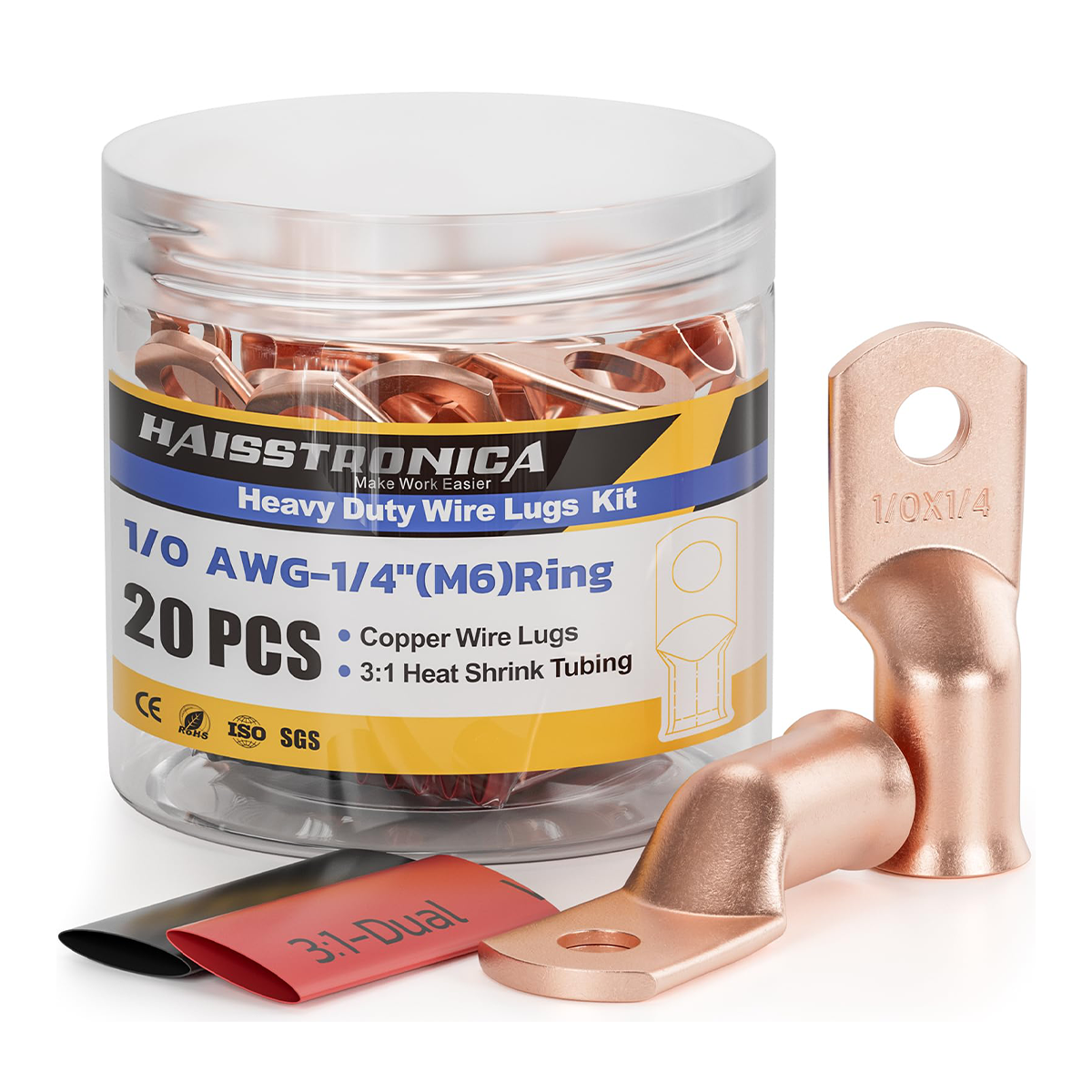
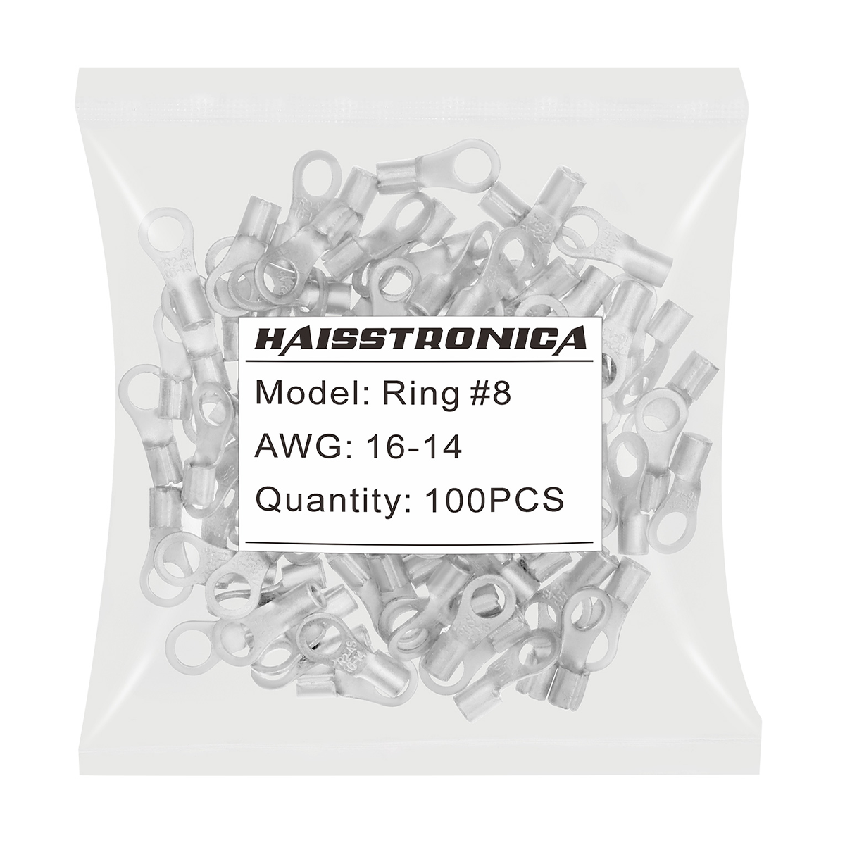
Identify all wire gauges at each connection, including the smaller fixture leads. Match conductor count, material, insulation diameter, and installation location to the connector's documented combinations. Strip only the length required by that connector.
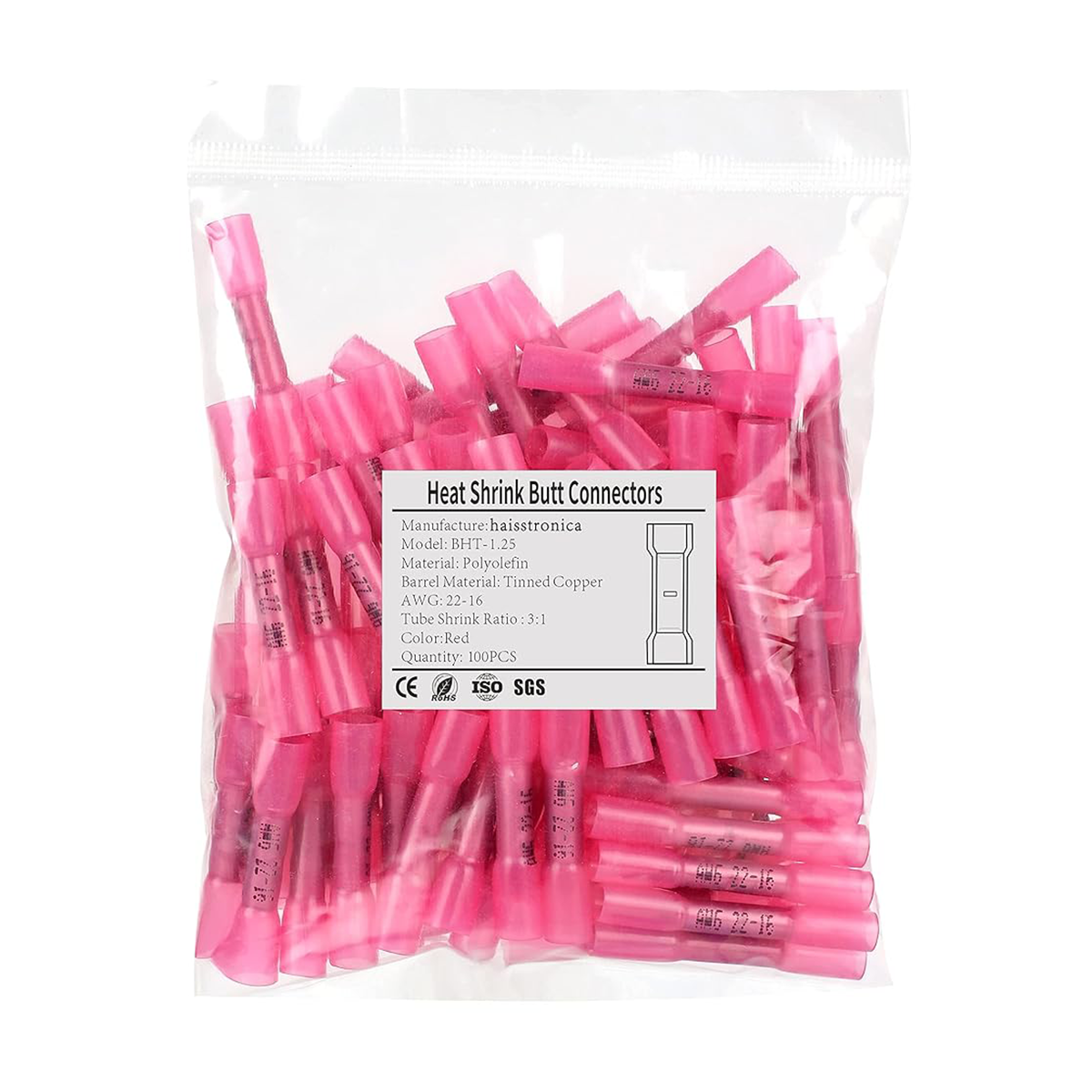
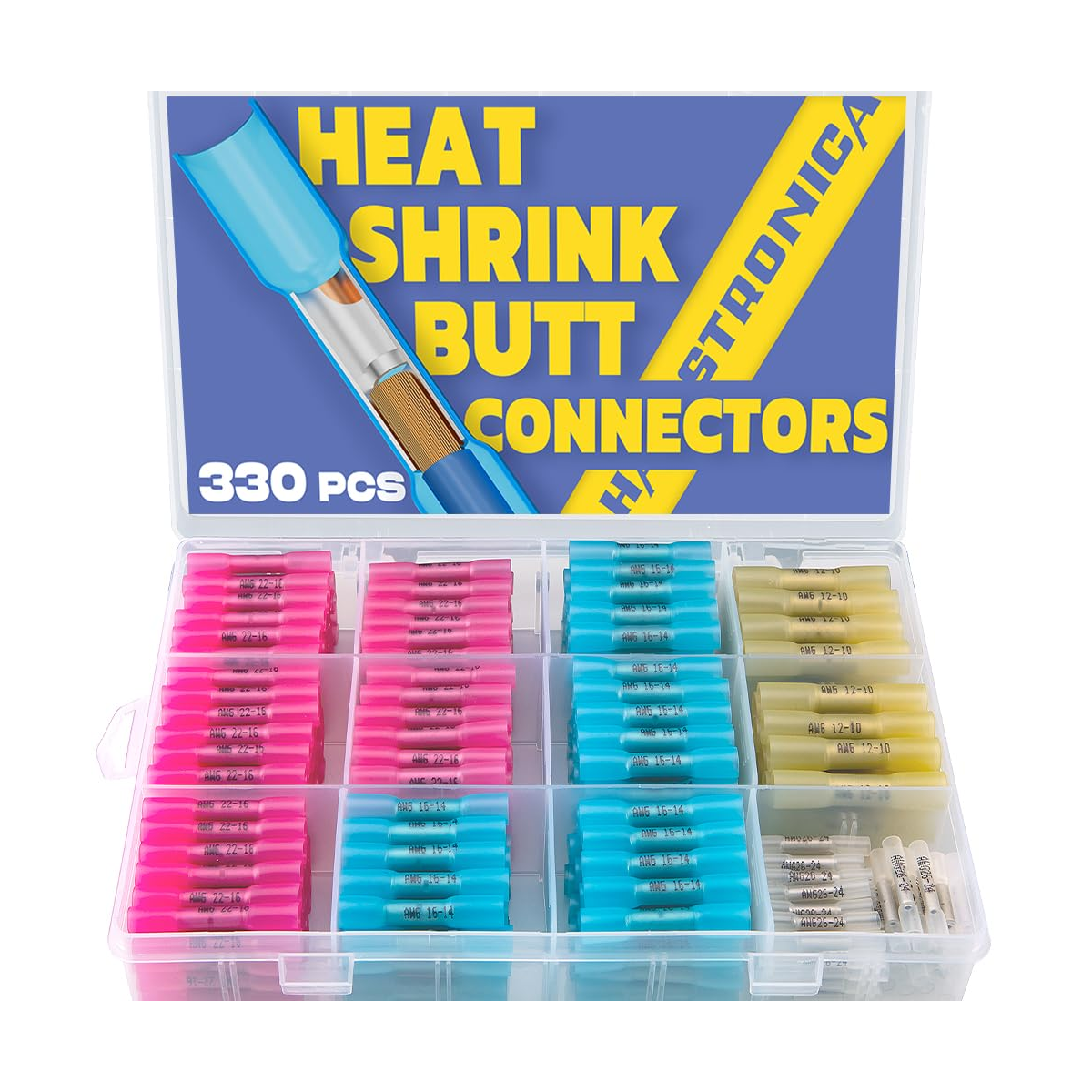
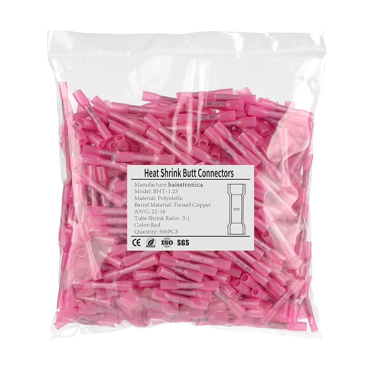
Two-wire inline joint: compare sealed butt connectors
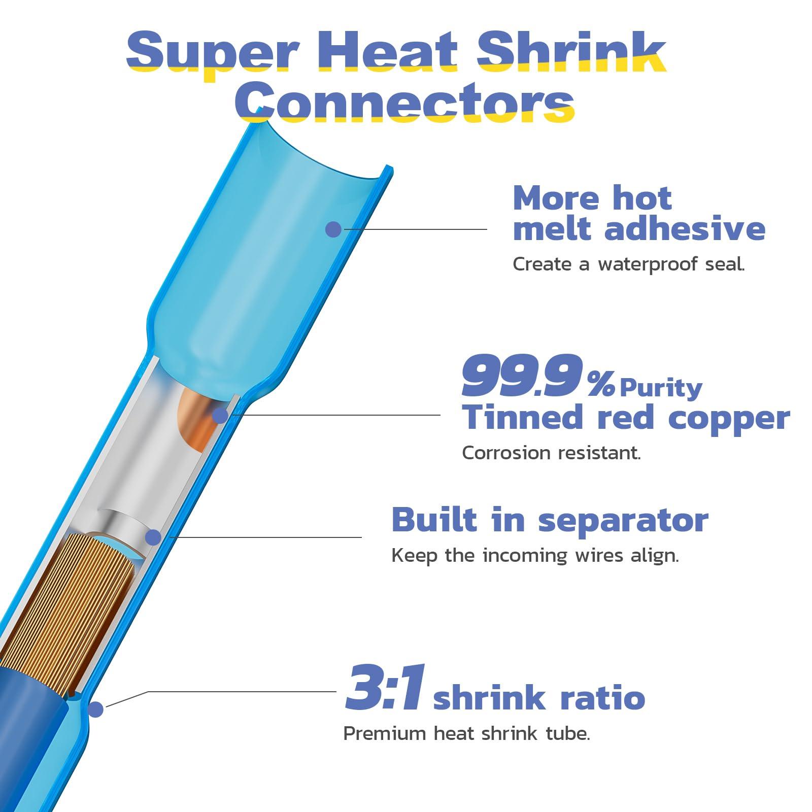
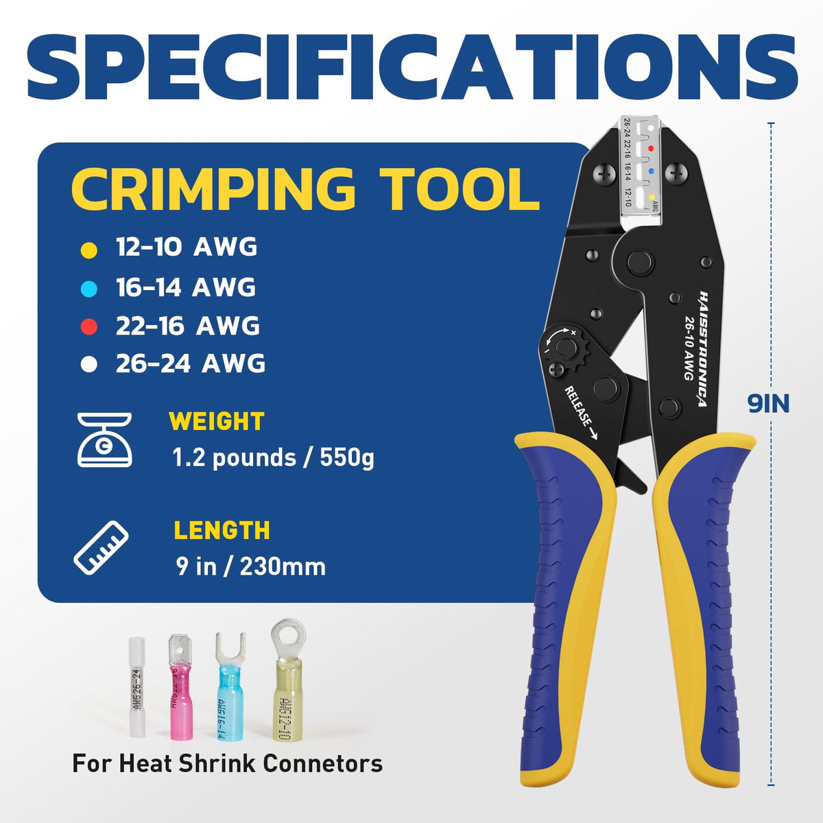
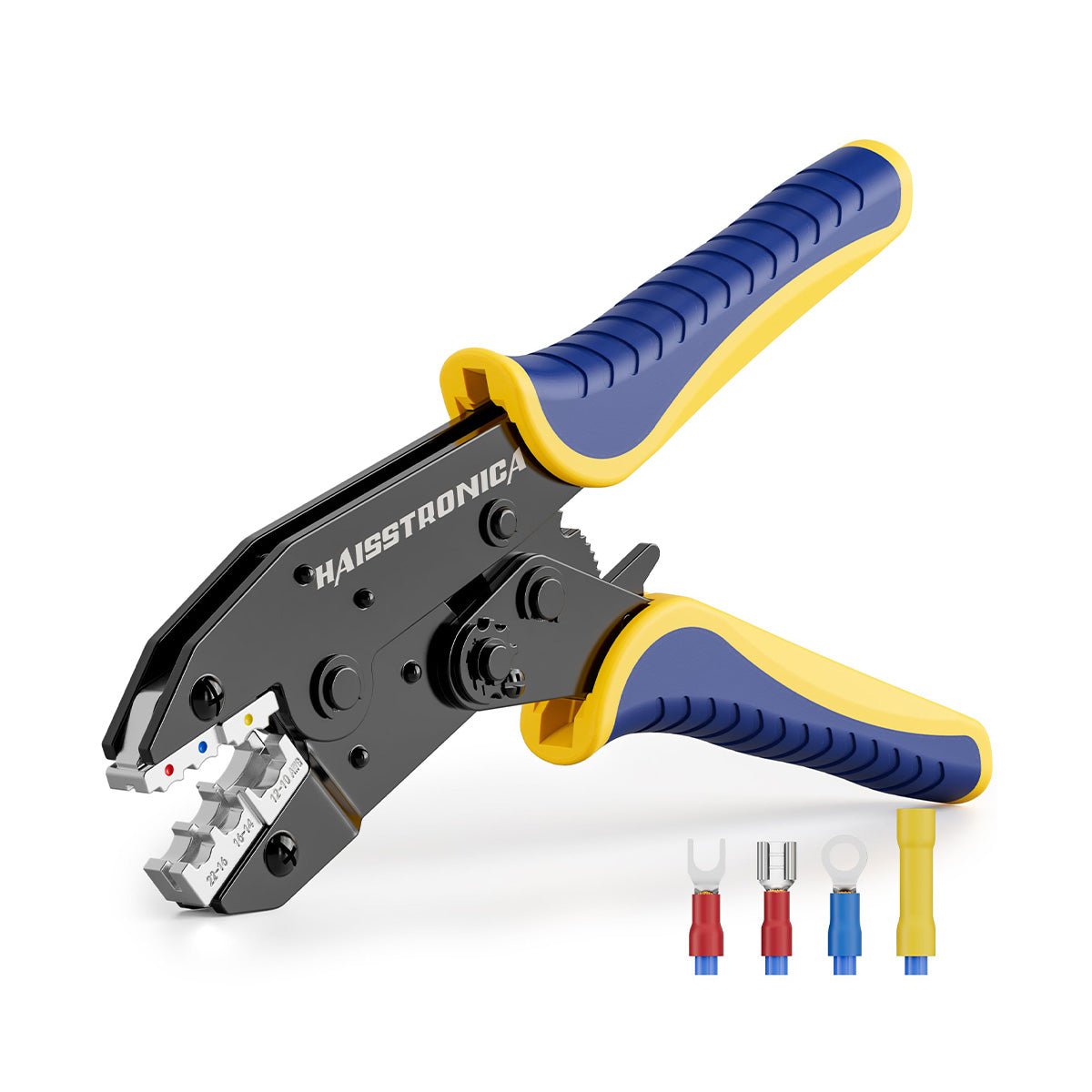
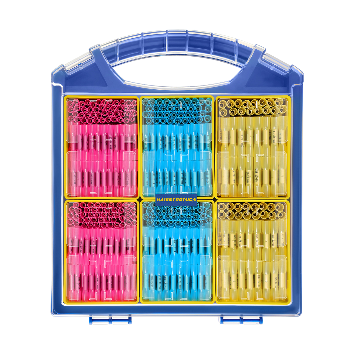
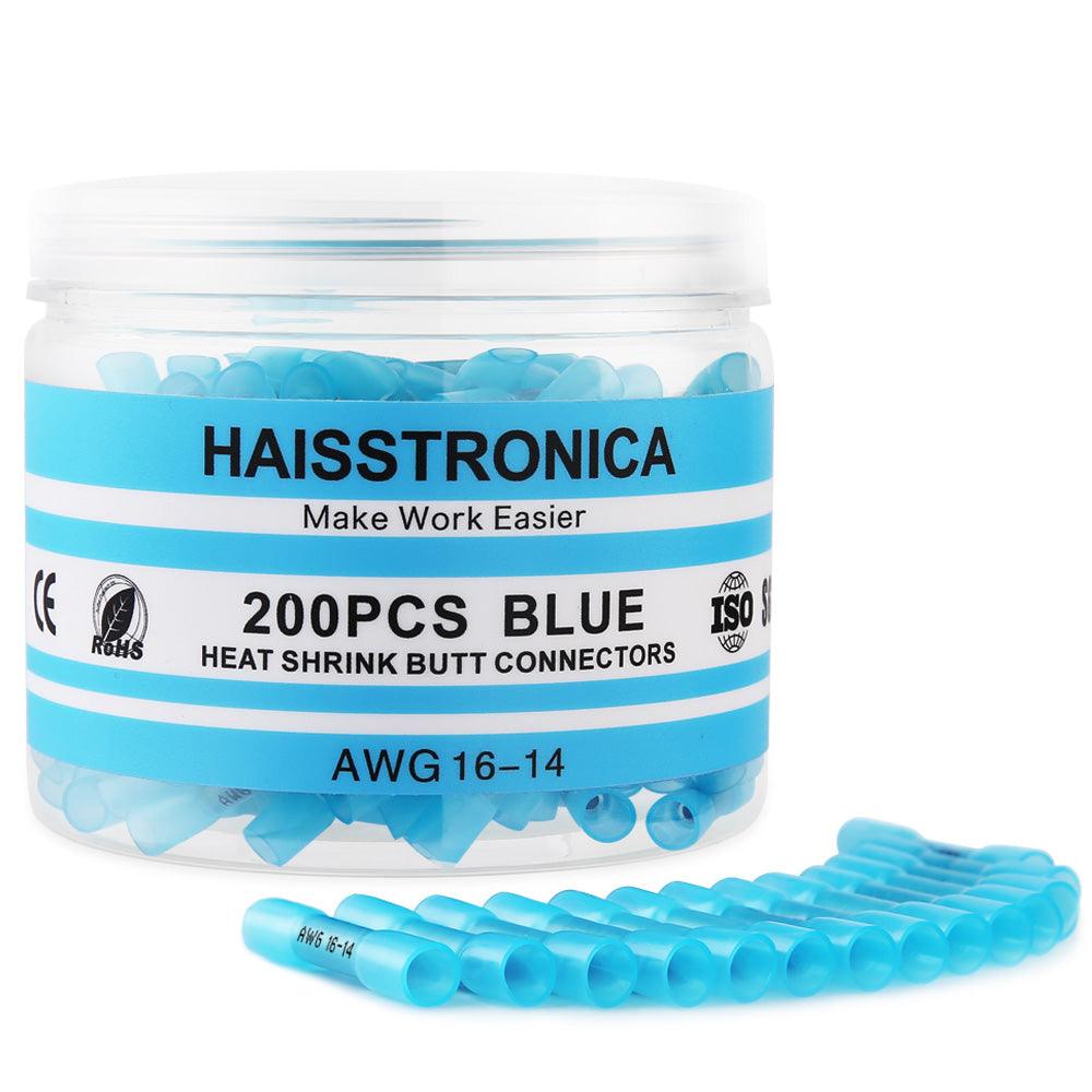
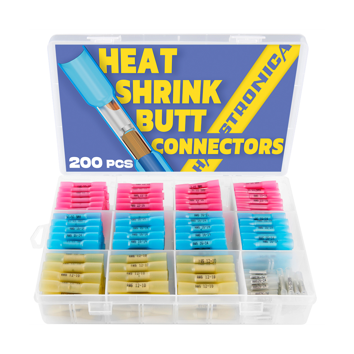
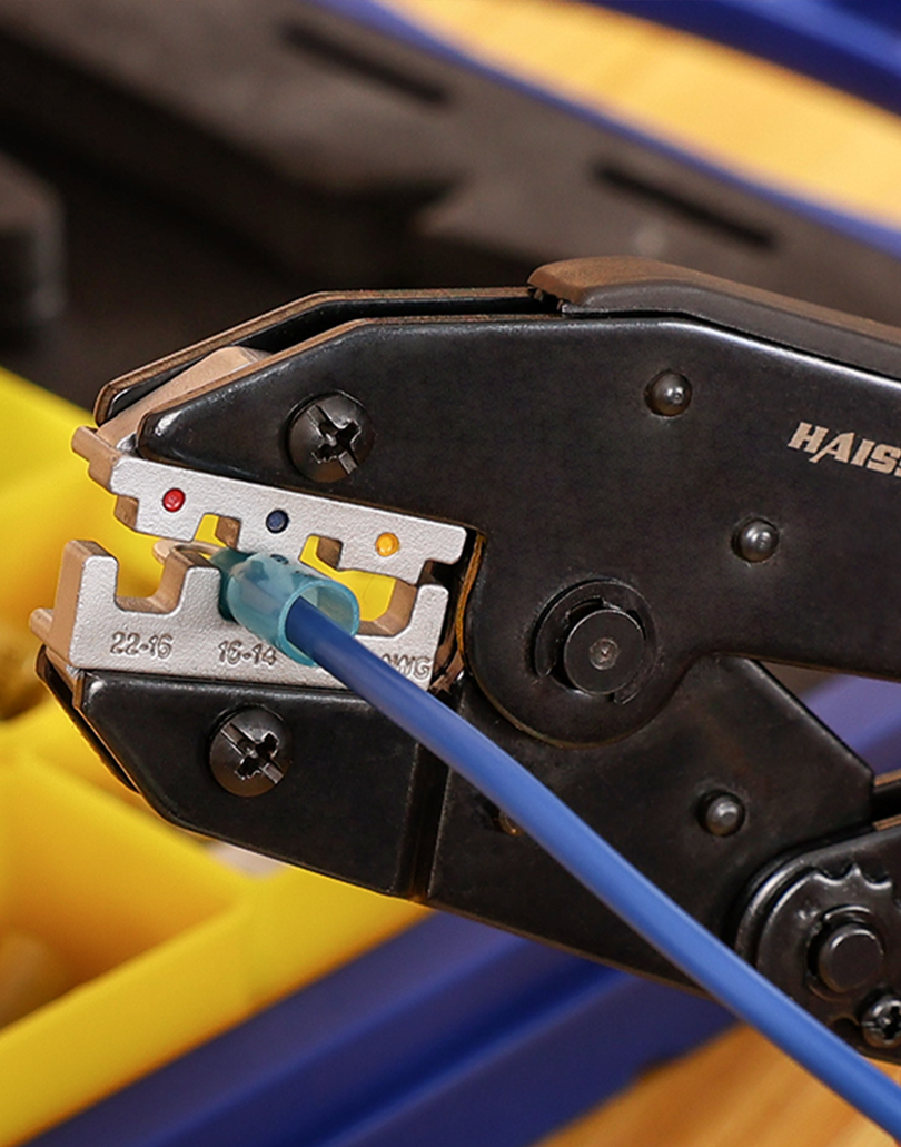
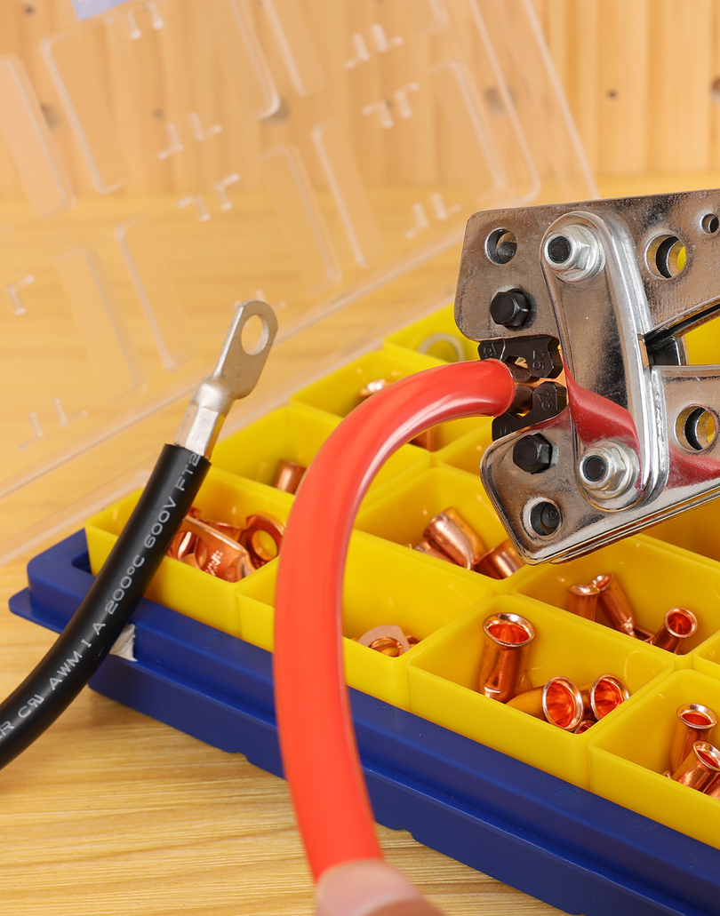
A butt connector can suit a permitted end-to-end join when each side fits its stated range. A two-conductor cable normally needs two separate splices. If the main and fixture lead have different gauges, verify a listed reducing combination rather than folding or doubling a small wire.
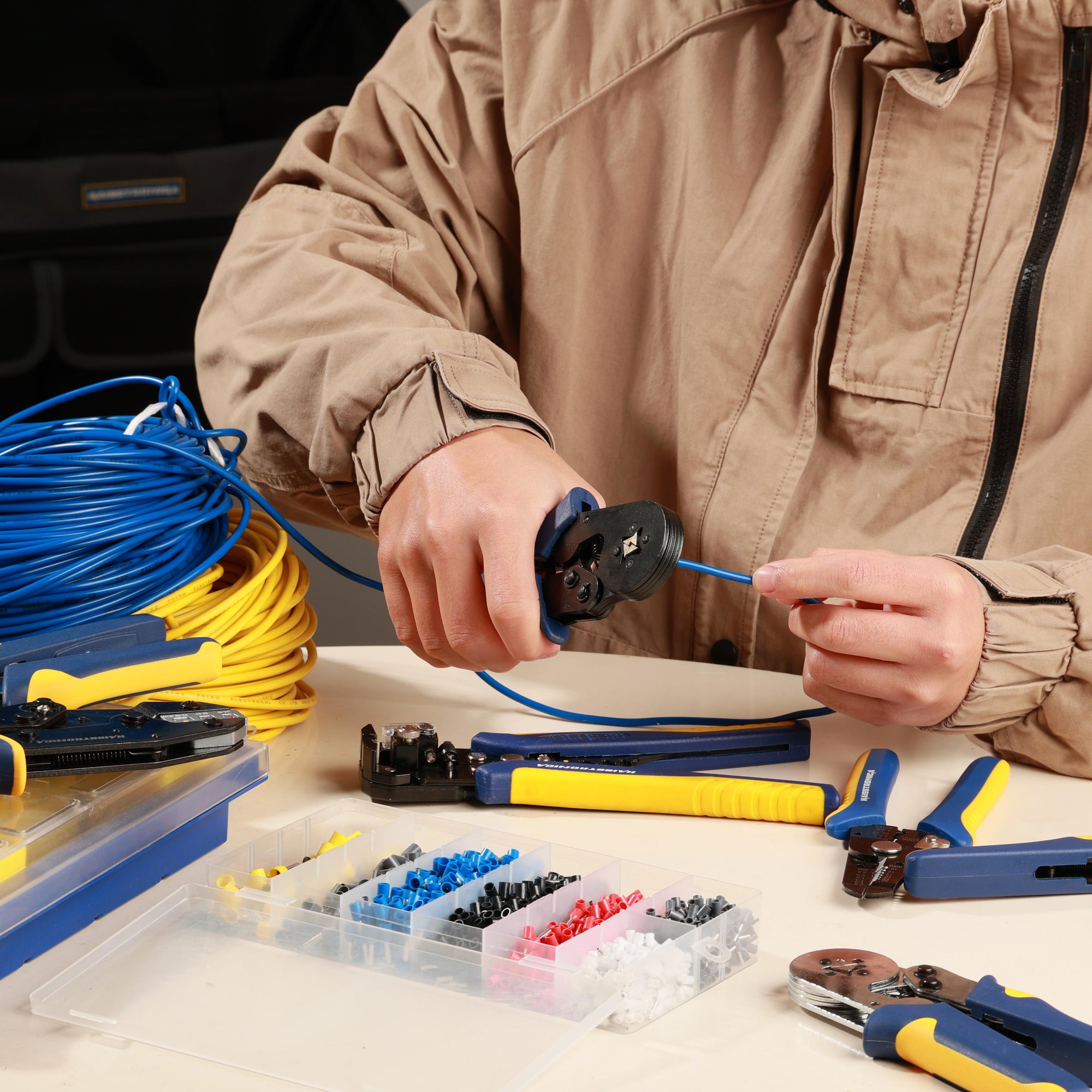
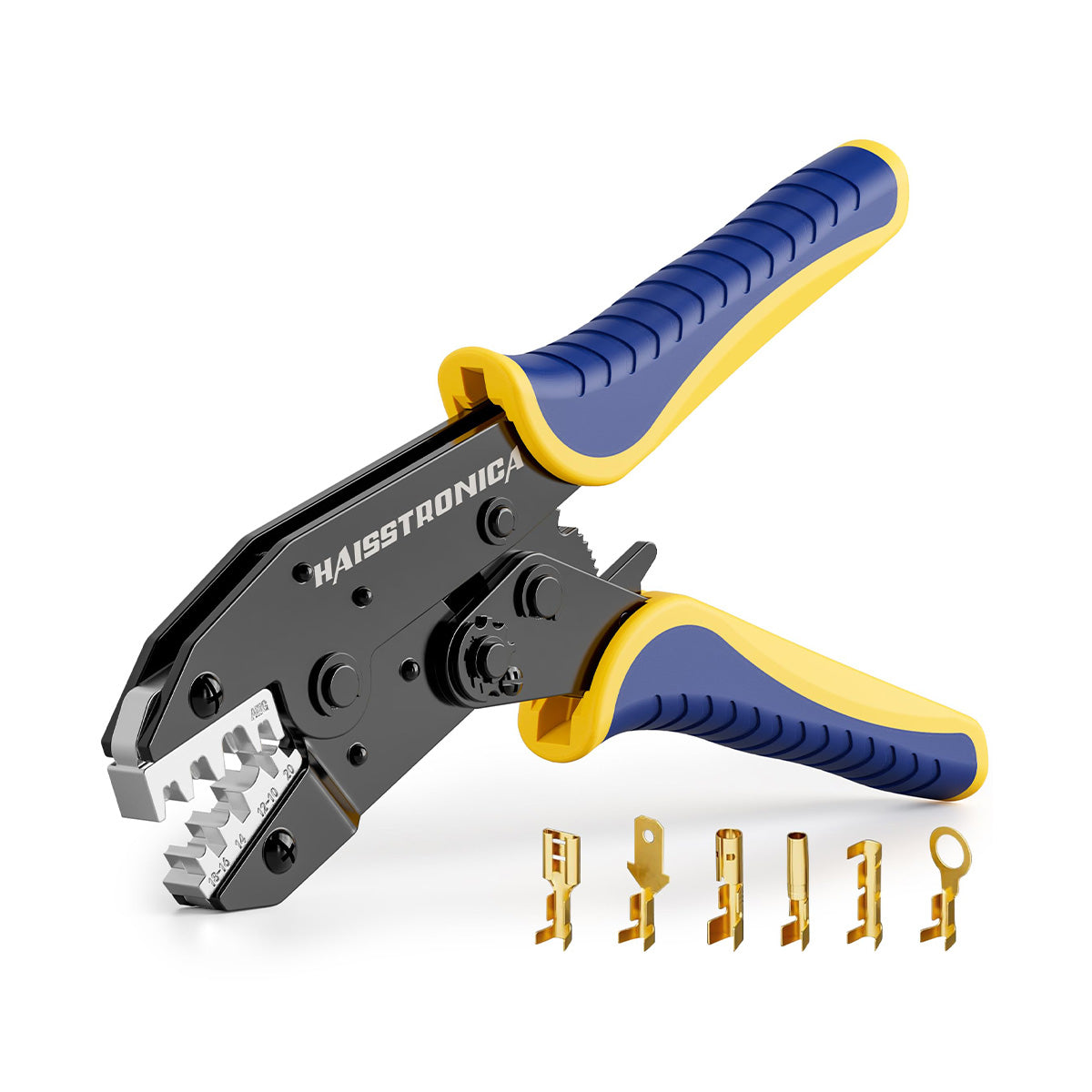
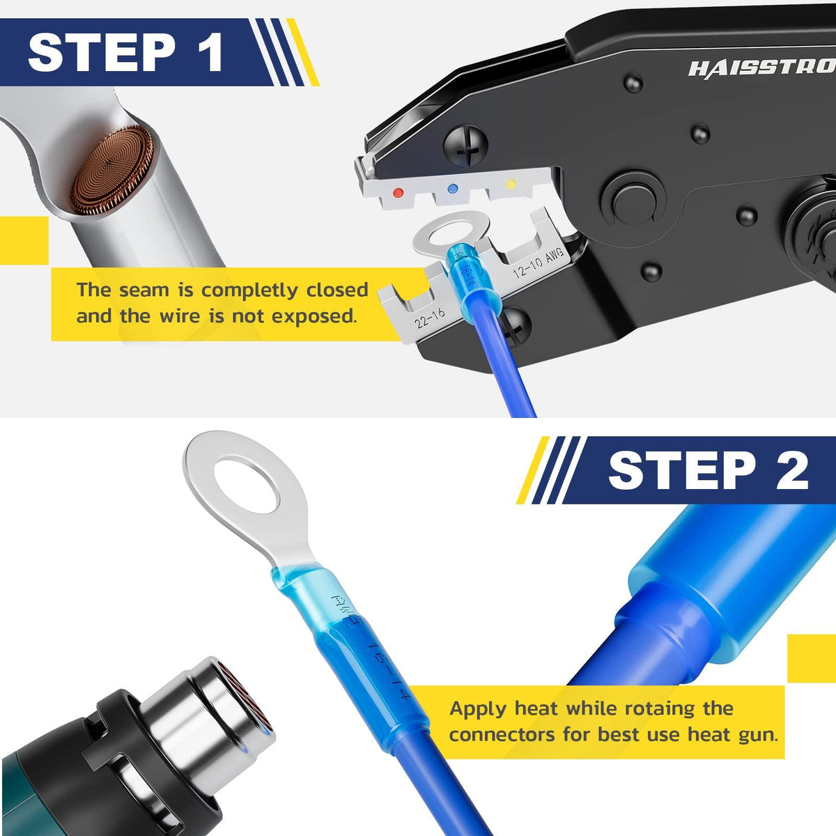
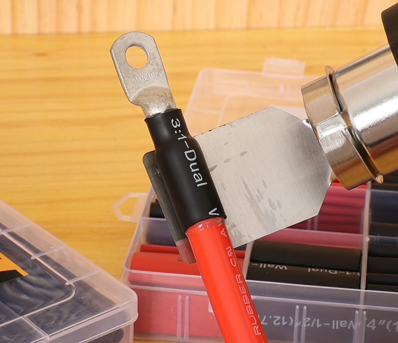
Use the matched die, make the mechanical crimp, apply controlled heat as instructed, and let the joint cool before inspection.
Fixture tap or T-branch: three wires are not a butt splice
Incoming cable, outgoing cable, and a fixture lead create a three-wire combination on each conductor. Use a connector expressly rated for that combination and location. Do not place multiple conductors into an ordinary two-wire butt connector unless its instructions specifically permit it.
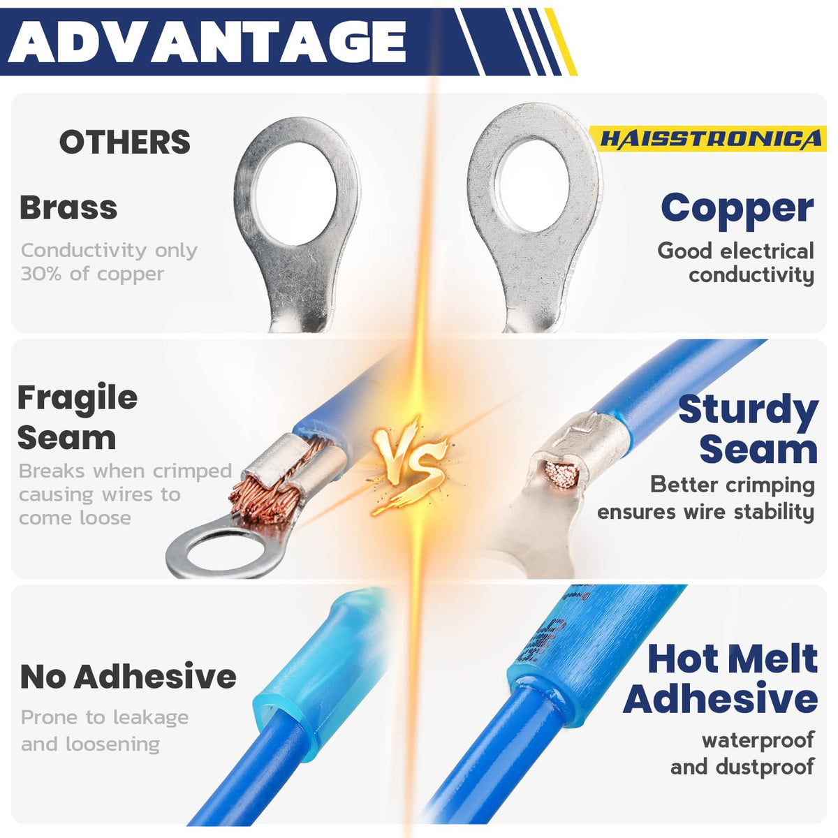
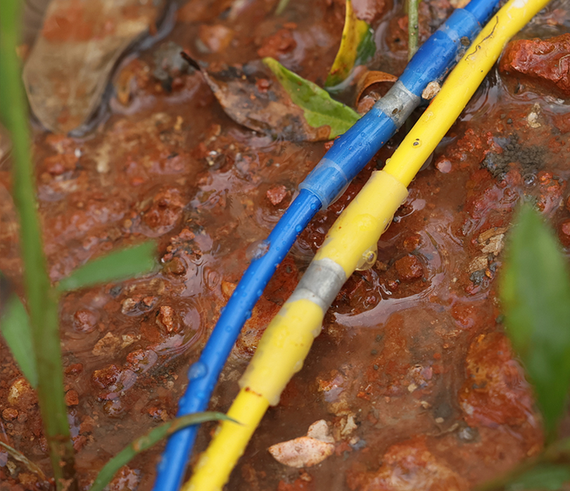
Waterproof is not automatically direct-burial approval. Confirm the complete connection system's wet-location and burial listing. The general kits below are not presented as universally approved buried T-junction systems.
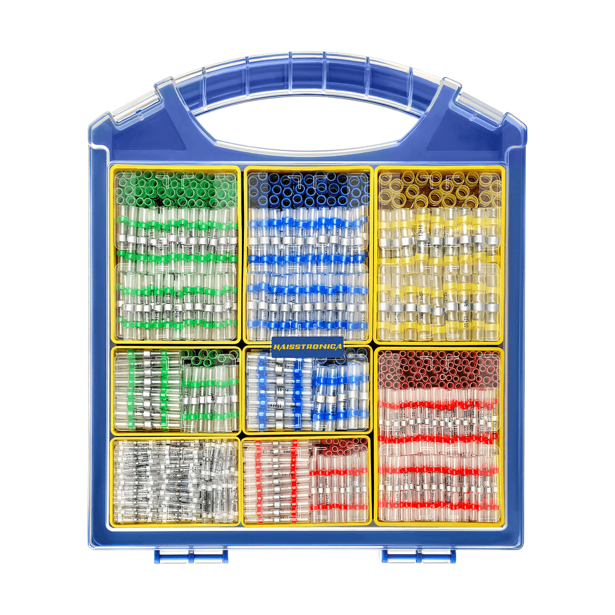
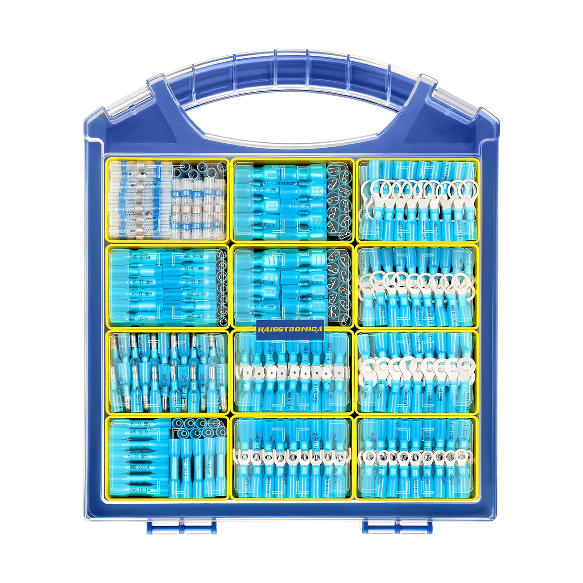
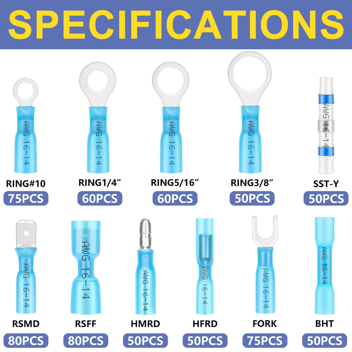
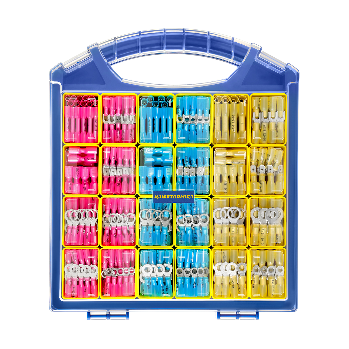
Review Waterproof Connection Options →Need preparation and sealing tools too?

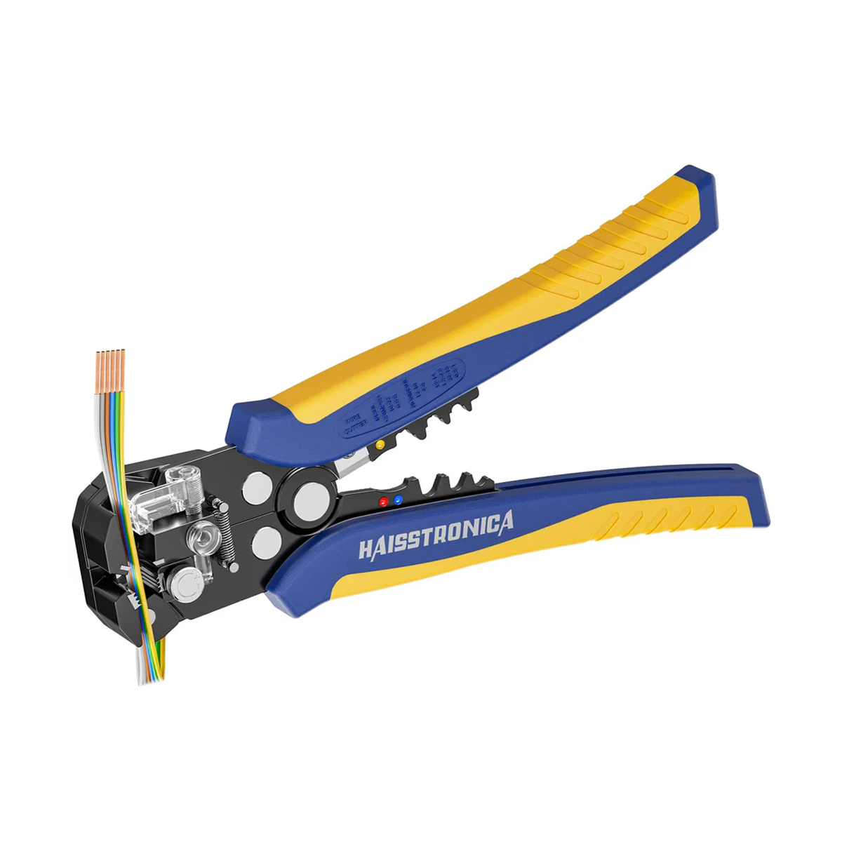
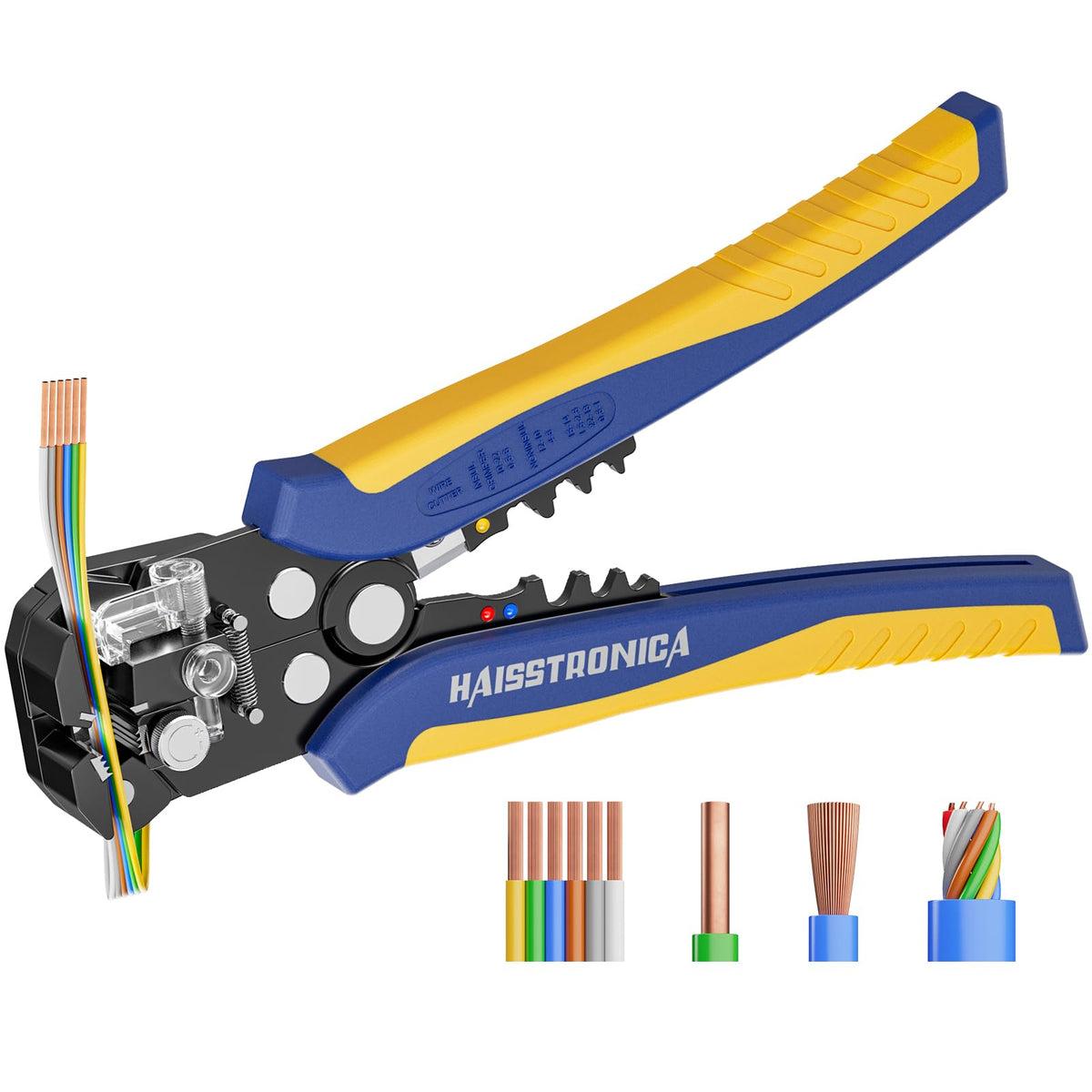
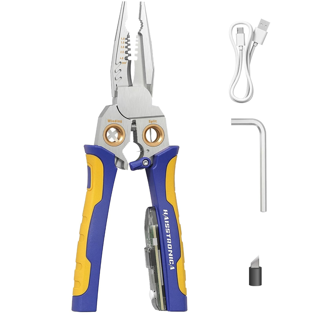
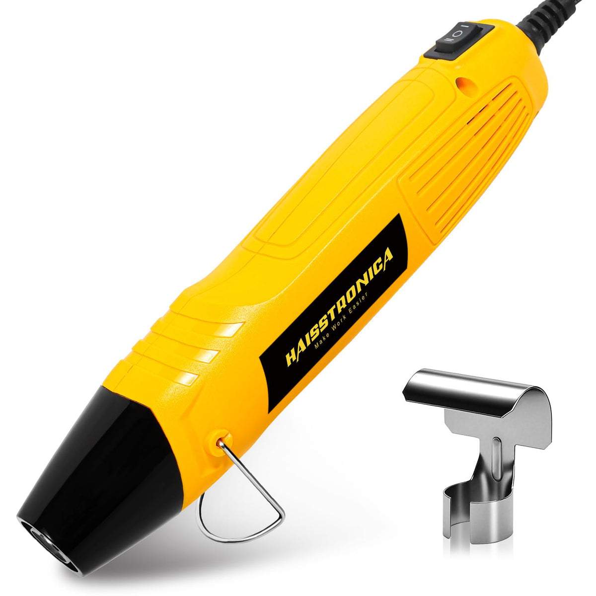
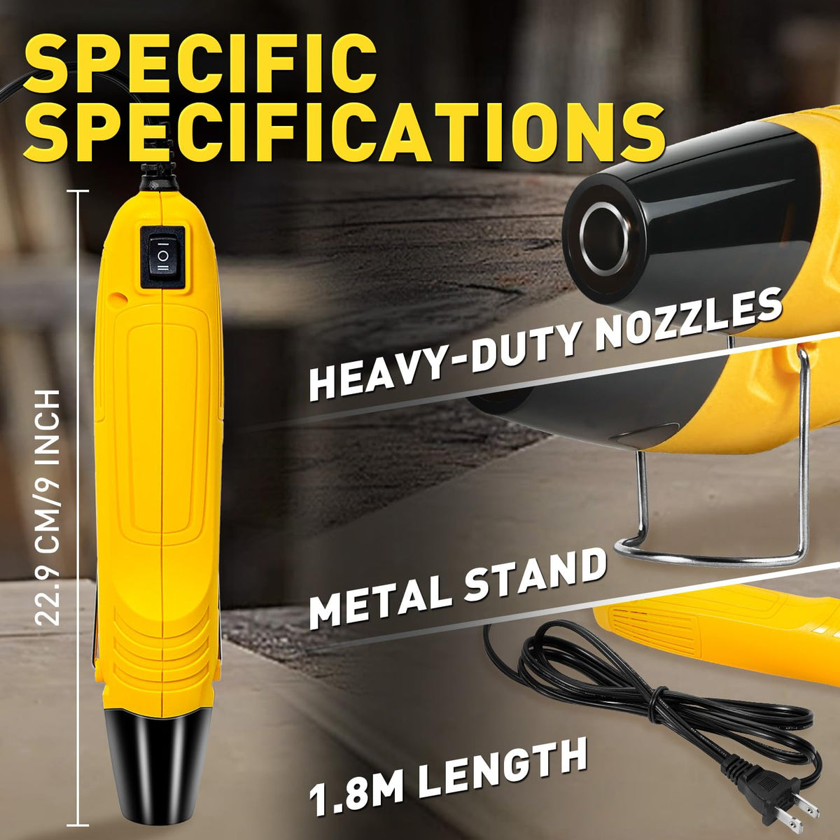
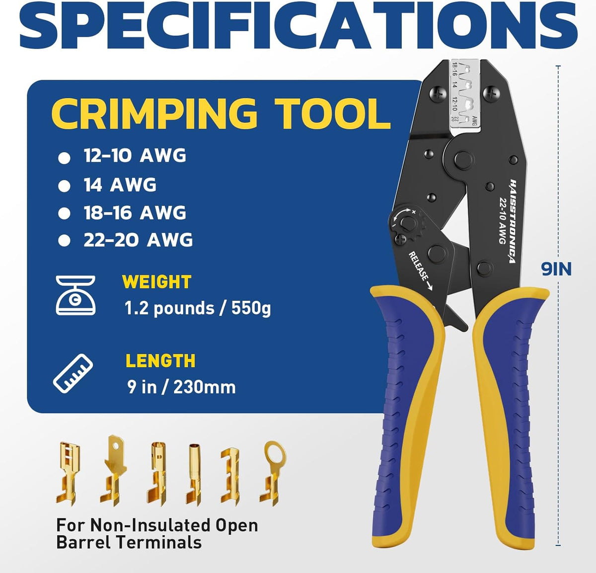
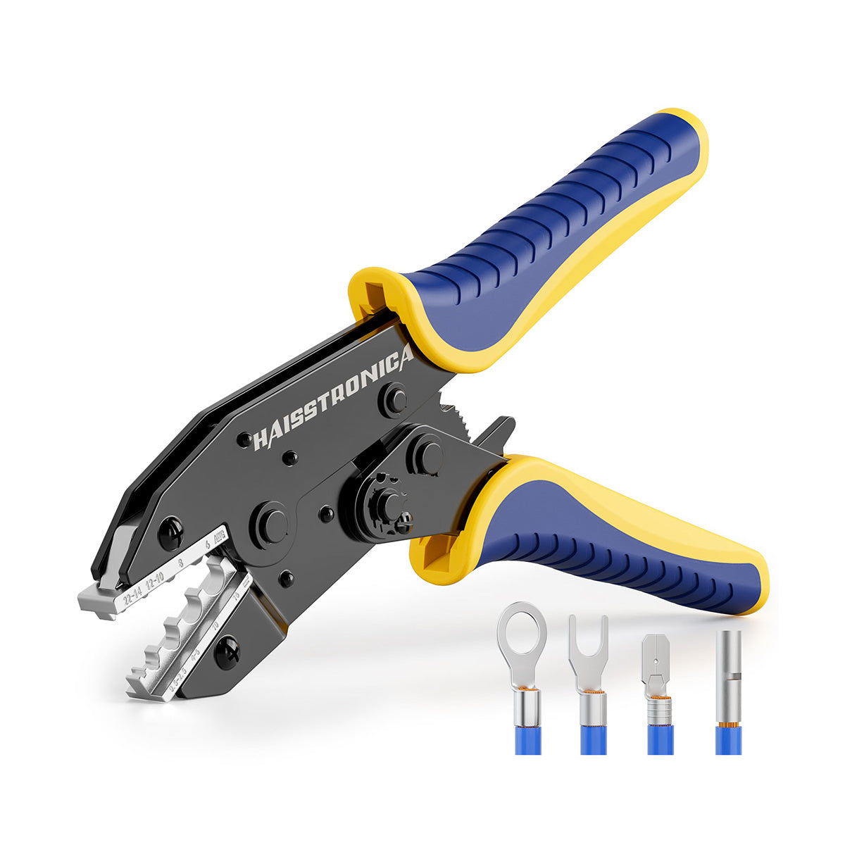
The Waterproof Wiring Seal Kit groups a stripper, ratchet crimper, heat gun, and sealing consumables. Compare it only if those items are missing from your setup.
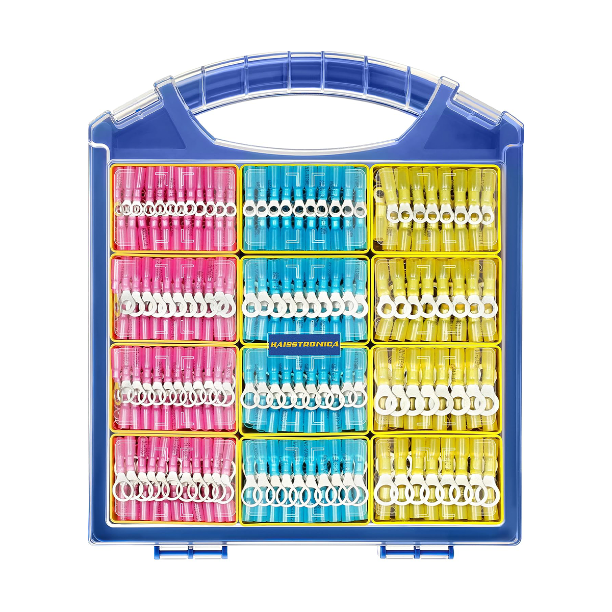
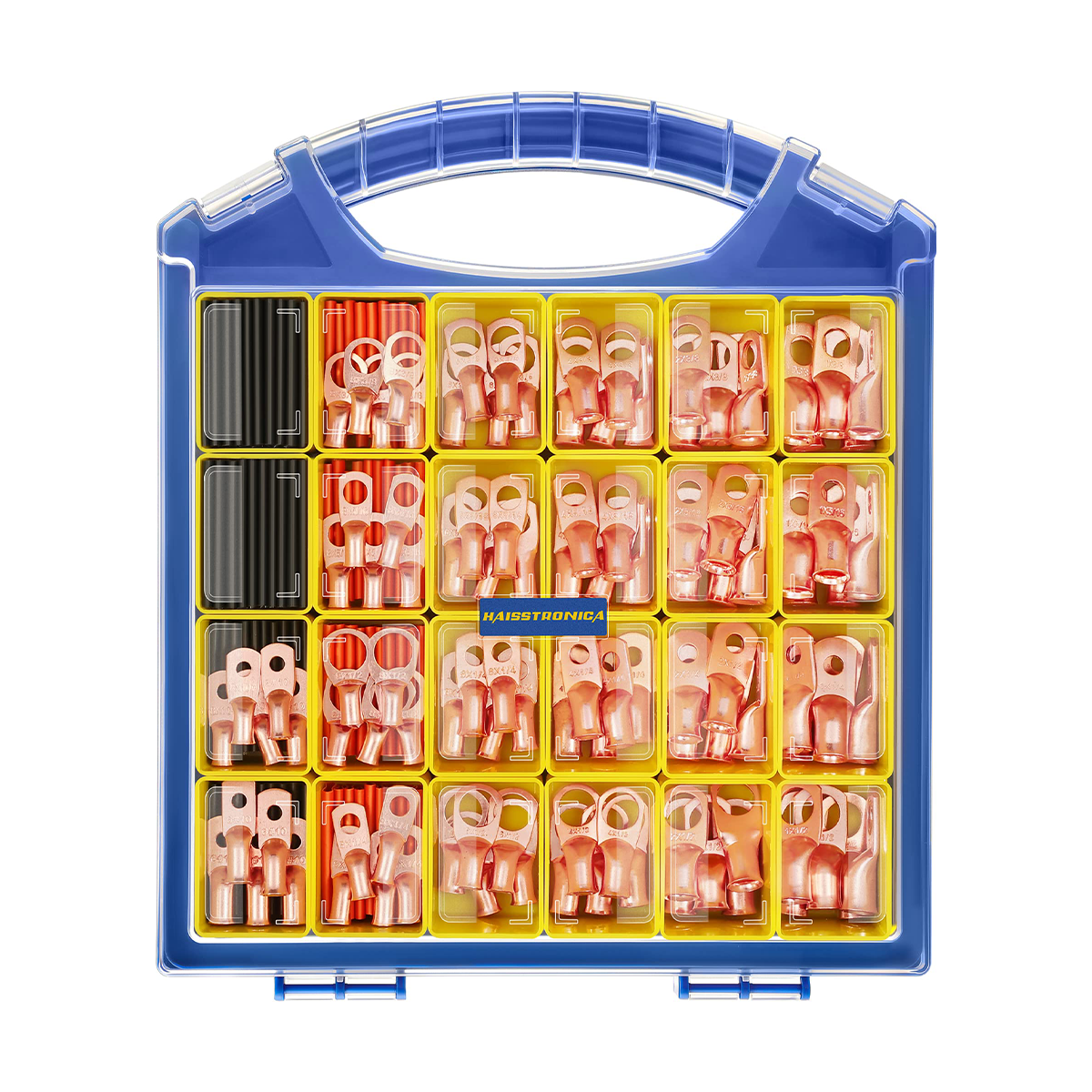
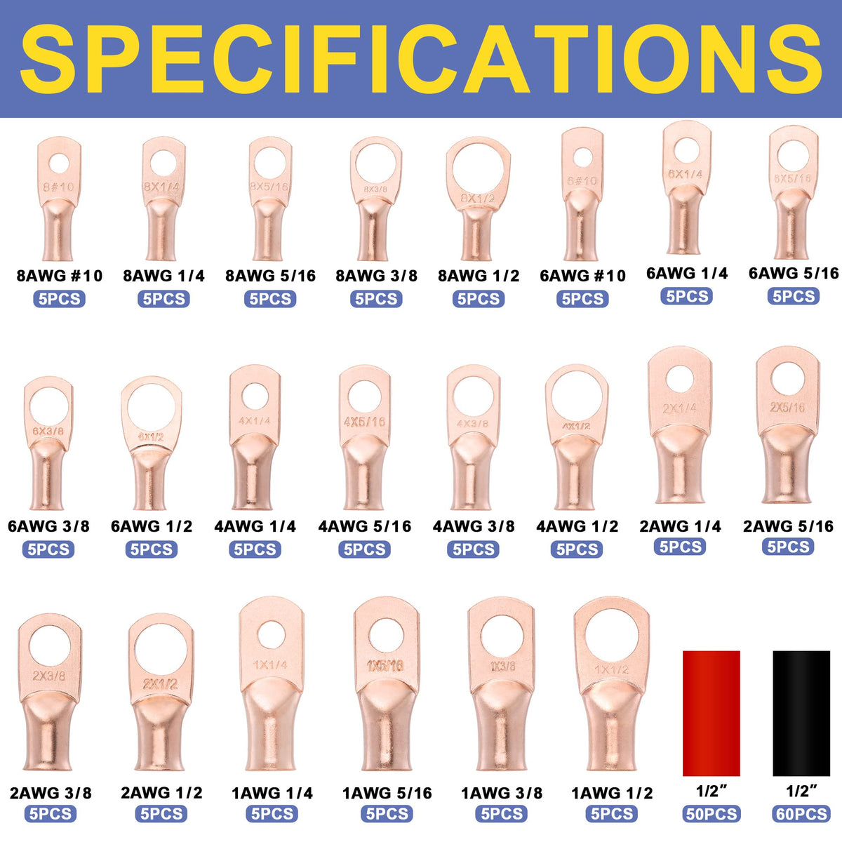
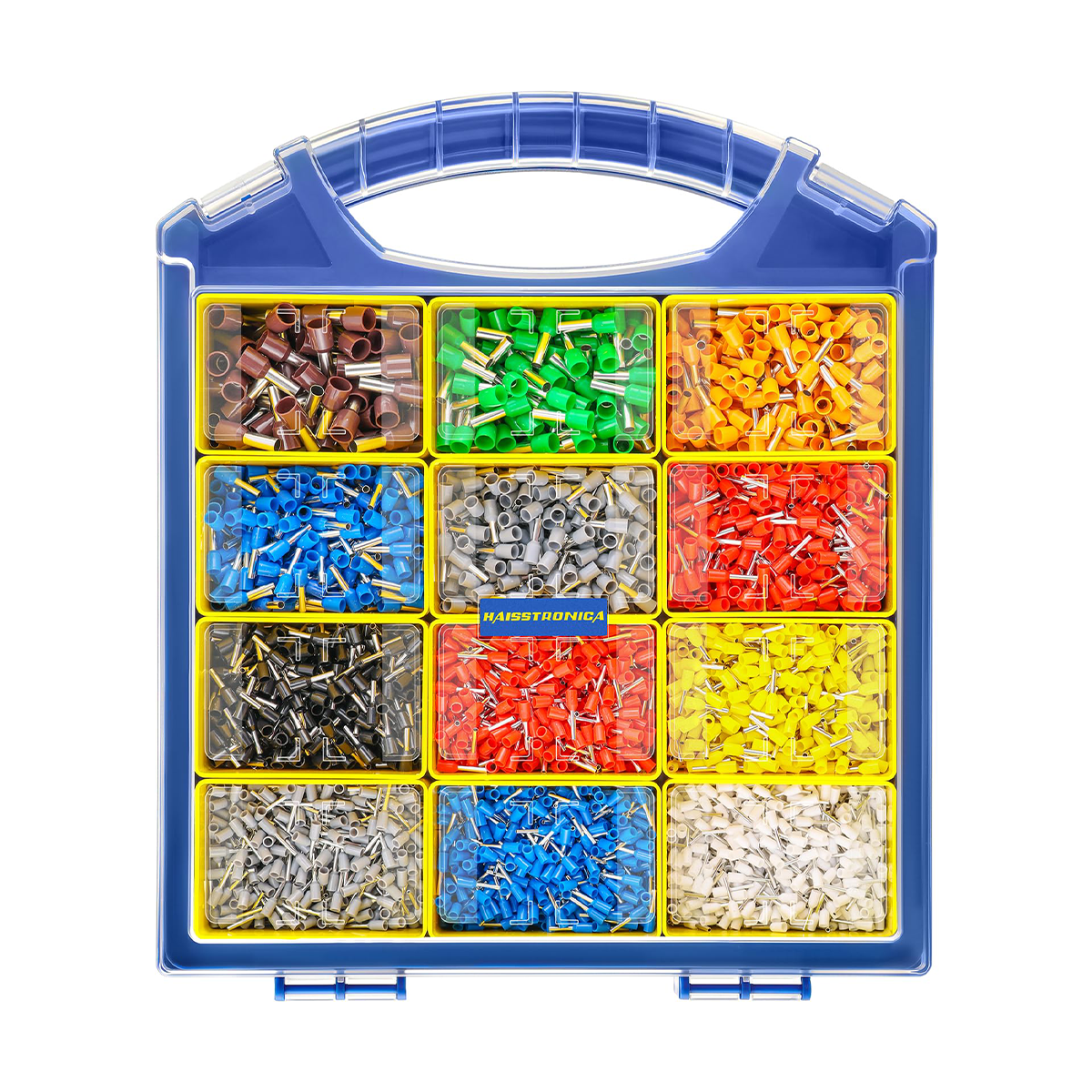
Check the usable quantity of your required connector size—not just the assortment's total piece count. A kit does not replace the need for a correctly rated branch connector.
5. Bury and protect the cable to the applicable requirements
Locate underground utilities before digging. Verify that the cable is listed for its route and follow the equipment instructions and local rules for burial depth, separation, crossings, and mechanical protection. There is no single trench-depth instruction that covers every site.
Keep service loops controlled and junction locations documented. Do not pull cable tight or leave exposed loops where people, tools, or animals can damage them. Complete the connection checks before backfilling; retain access where the connection system requires it.
Safety reference: FX Luminaire EX transformer installation instructions. Its dimensions and limits apply to that equipment, not automatically to your system.
6. Energize, measure, and adjust
- Before power: inspect every termination, seal, cable route, and transformer connection; ensure the equipment is closed and protected as instructed.
- With all fixtures on: check the transformer output and the voltage at the nearest and farthest fixtures. Use the correct AC or DC meter setting and stay within the low-voltage test points specified by the manufacturer.
- If lights are dim or inconsistent: investigate loose joins, overloaded outputs, voltage drop, and incompatible fixtures. Switch power off before correcting wiring. A higher tap is acceptable only when every fixture remains within its permitted voltage range.
- At night: adjust beam direction, check glare, program timers, and record the final layout and measurements for maintenance.
Your project procurement list
Calculate above to generate the wire allowance and connection counts for this circuit. Availability does not change the electrical requirement.
- Cable: selected gauge + total installed route + reserve, then verify a workable spool cut plan.
- Two-wire splices: 2 × (end fixtures + inline cable joins), plus spares.
- Three-wire branch connectors: 2 × (fixture taps + extra T-junctions), plus spares.
- Separate checks: compatible fixtures and transformer, approved protection, and any missing tools.