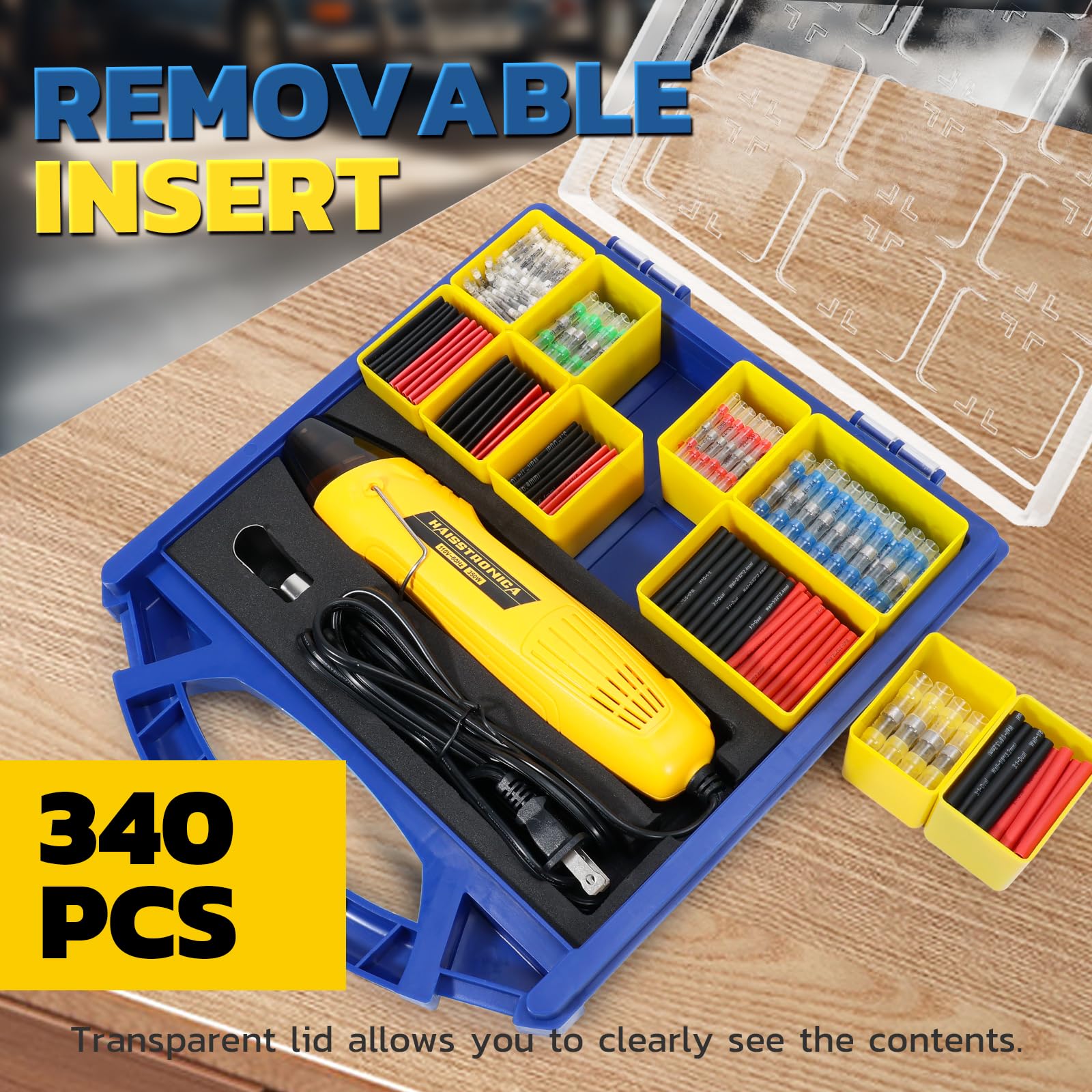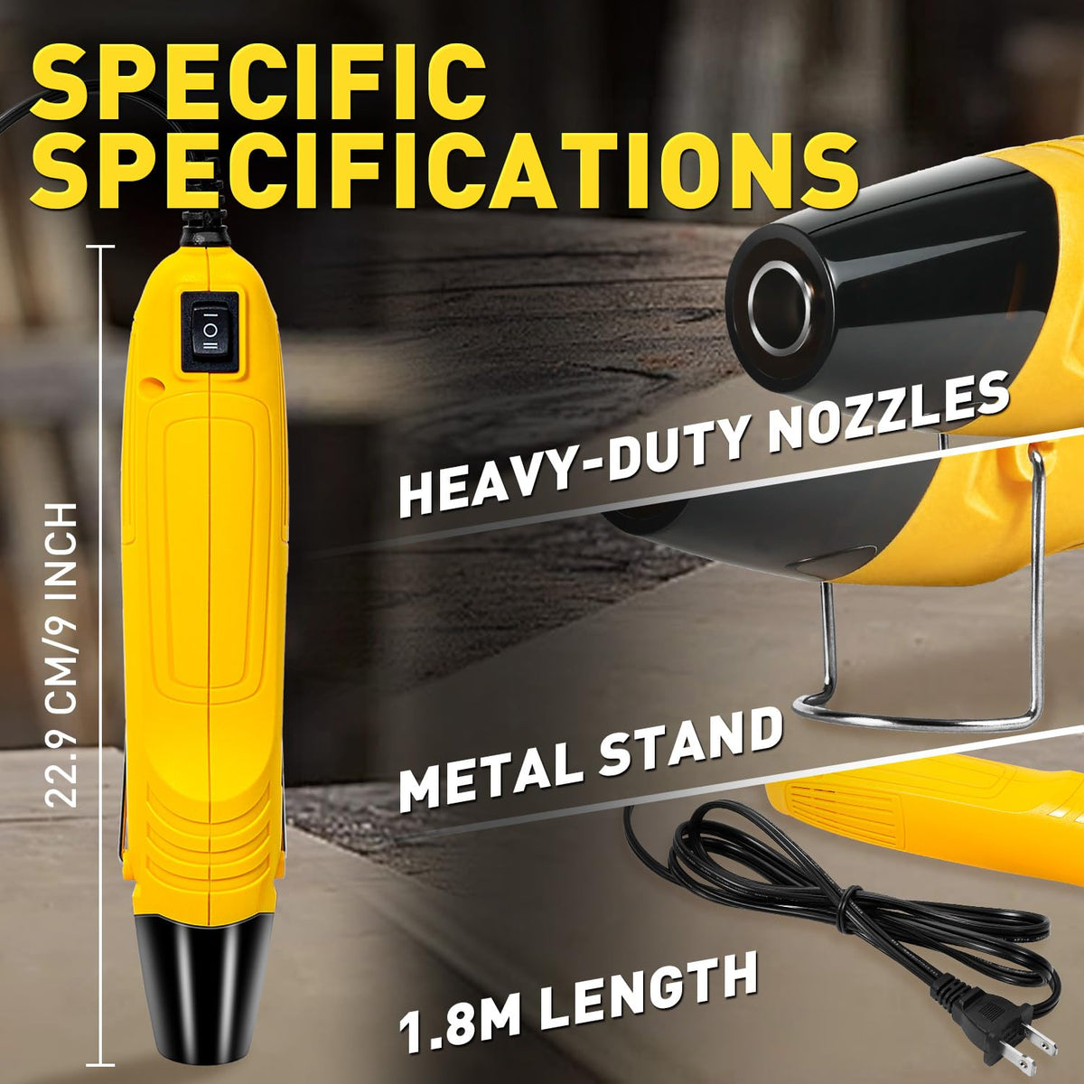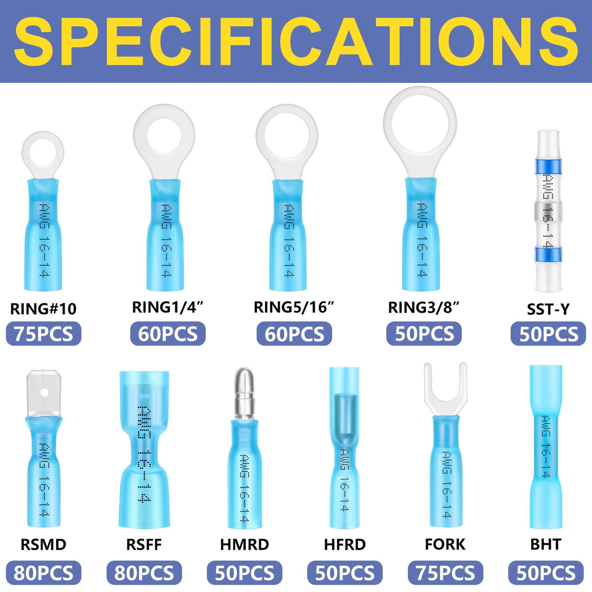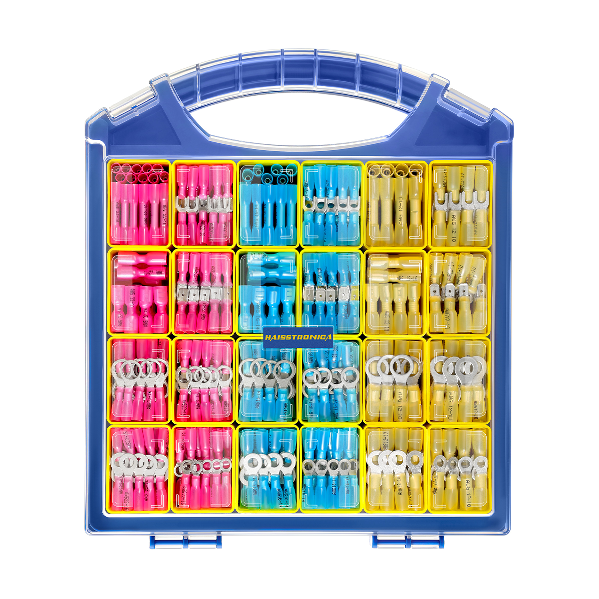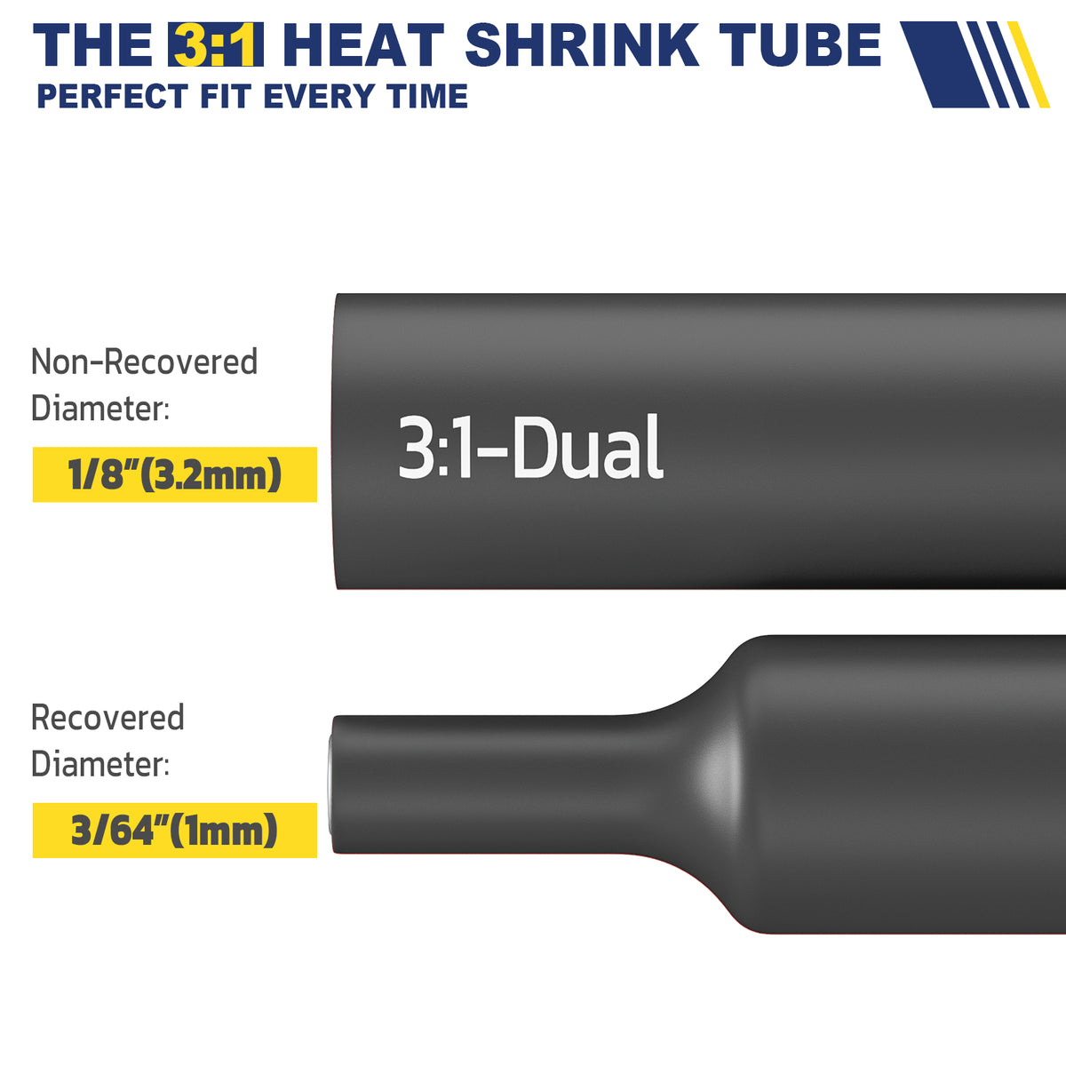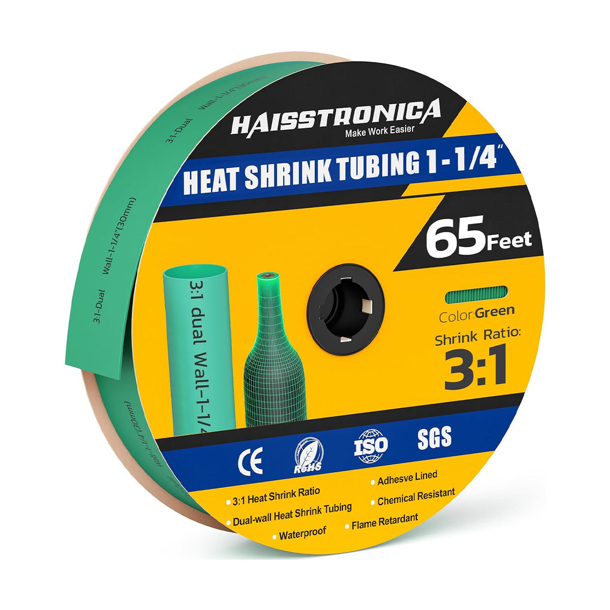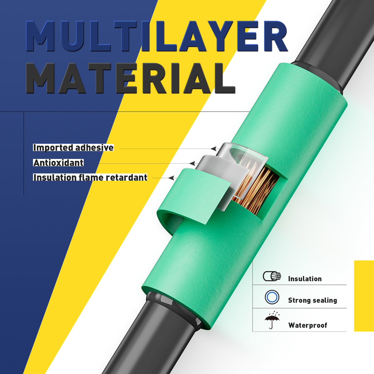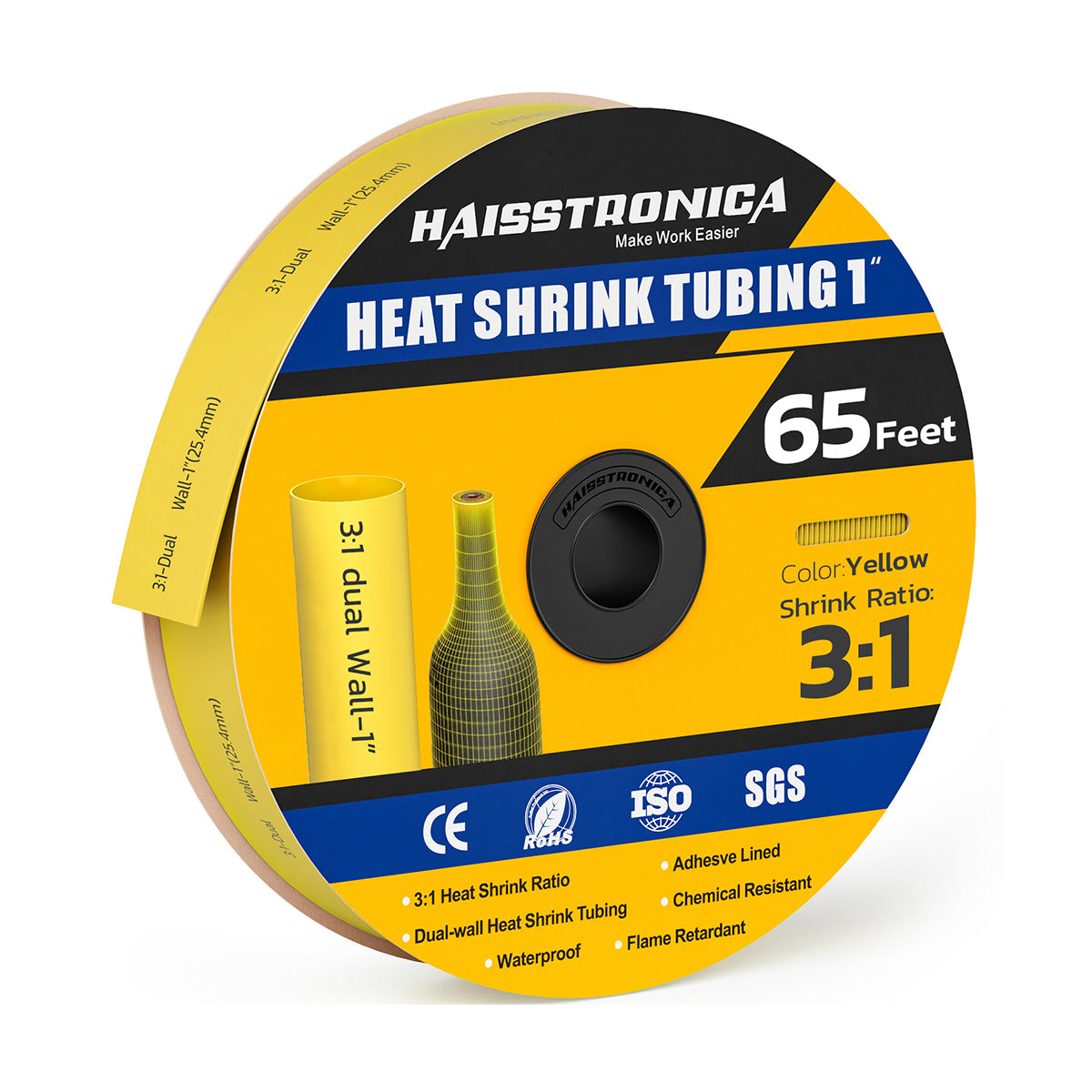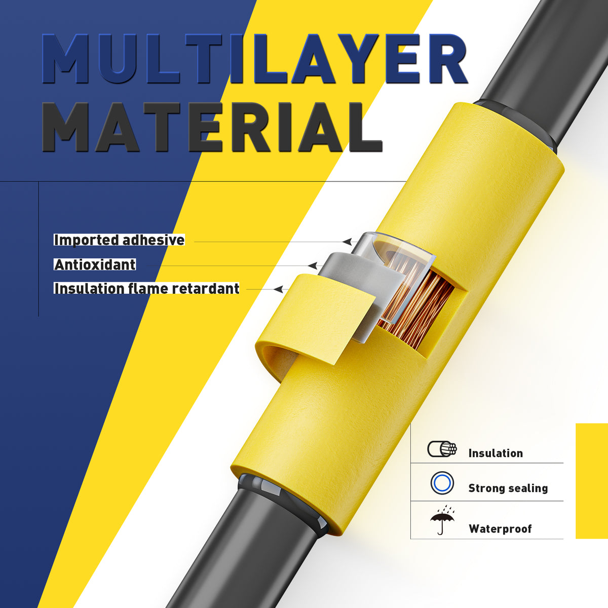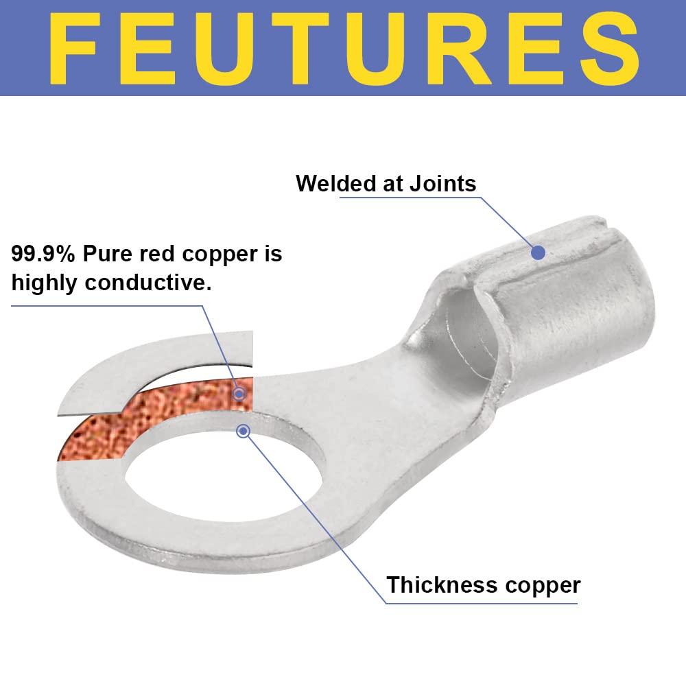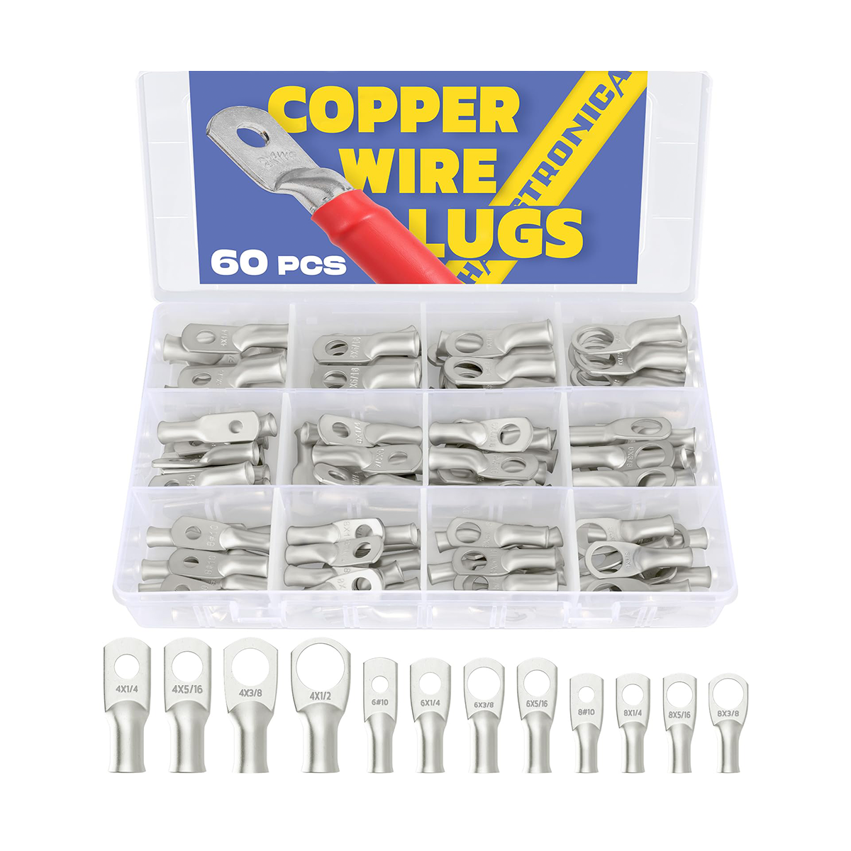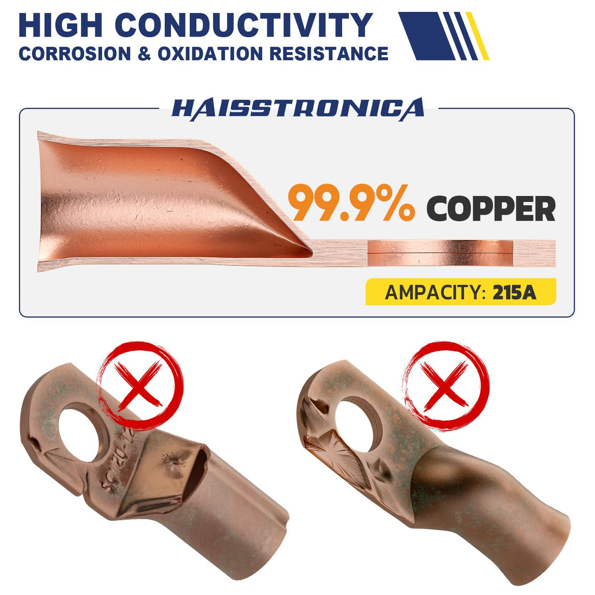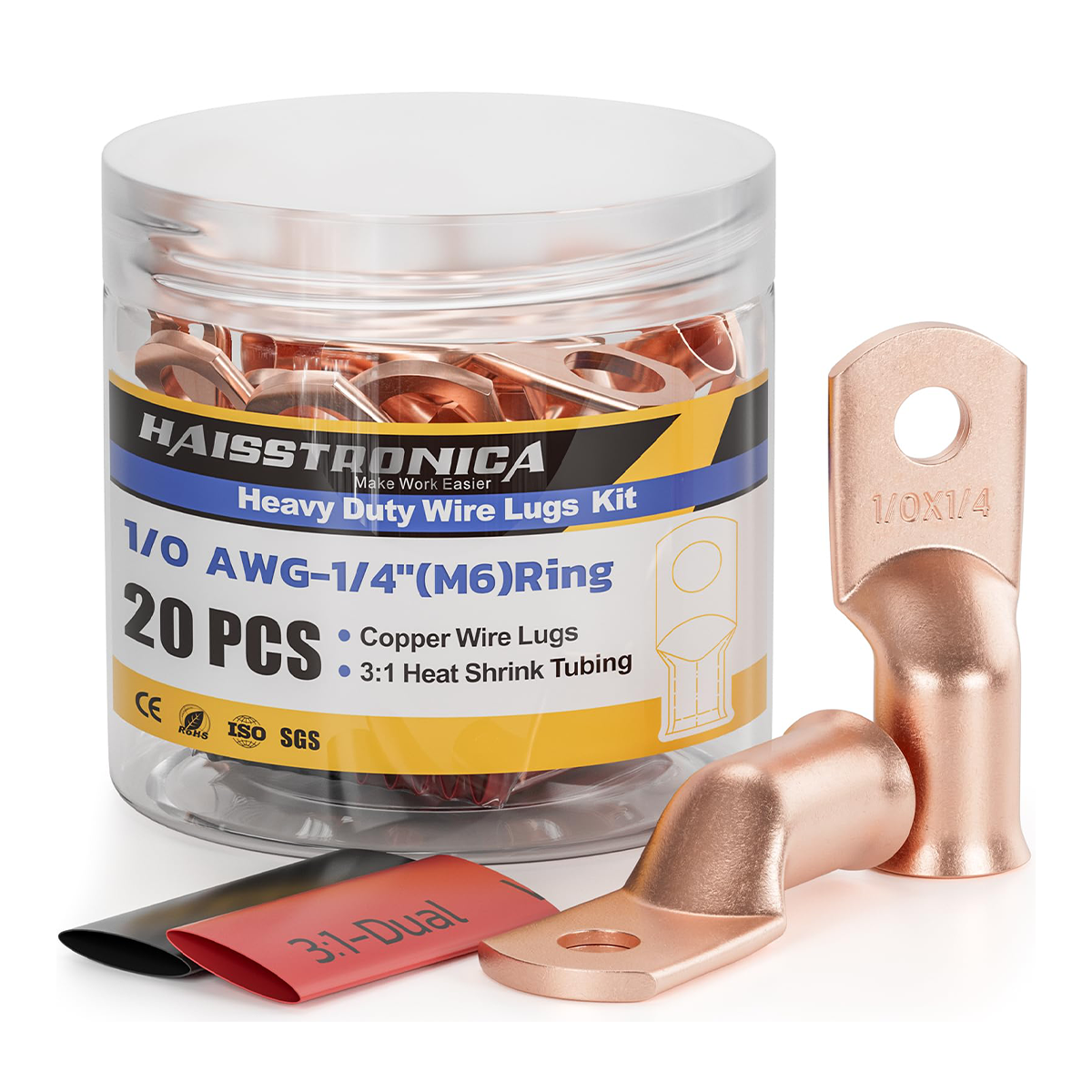
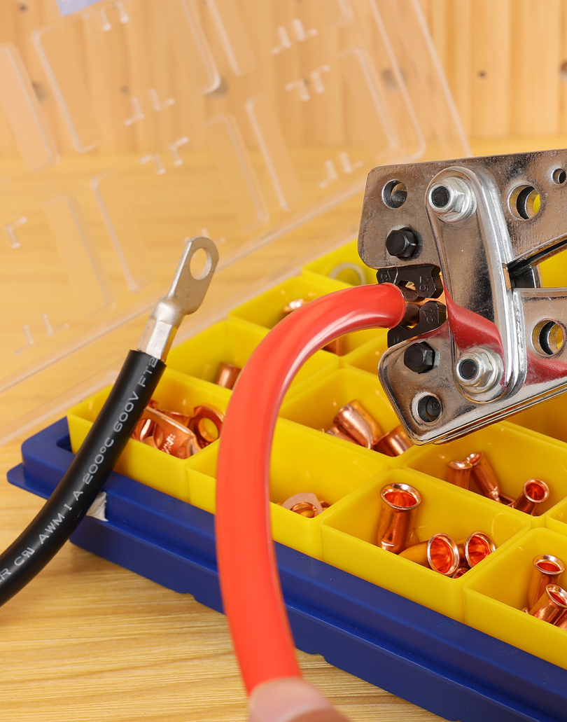
For sustained vibration, choose a sealed crimp—not solder alone.
A matched crimp connector keeps the conductor flexible outside the barrel. Add adhesive-lined heat shrink and proper strain relief for automotive, marine, trailer, and mobile equipment wiring.

1. Rate vibration and temperature before choosing
Start with the real operating environment. A stationary indoor enclosure and an engine bay do not impose the same mechanical or thermal stress.
Static or protected wiring
Benchtop electronics, protected cabinets, and stationary low-current projects may allow more connection methods when permitted by the equipment requirements.
Vehicle, boat, trailer, machine
Repeated flexing and shock favor a controlled mechanical crimp, sealed insulation, secure routing, and strain relief.
Check the full operating range
Confirm the connector sleeve, conductor insulation, and nearby heat sources are compatible. Never rely on connector color alone.
Wet or corrosive exposure
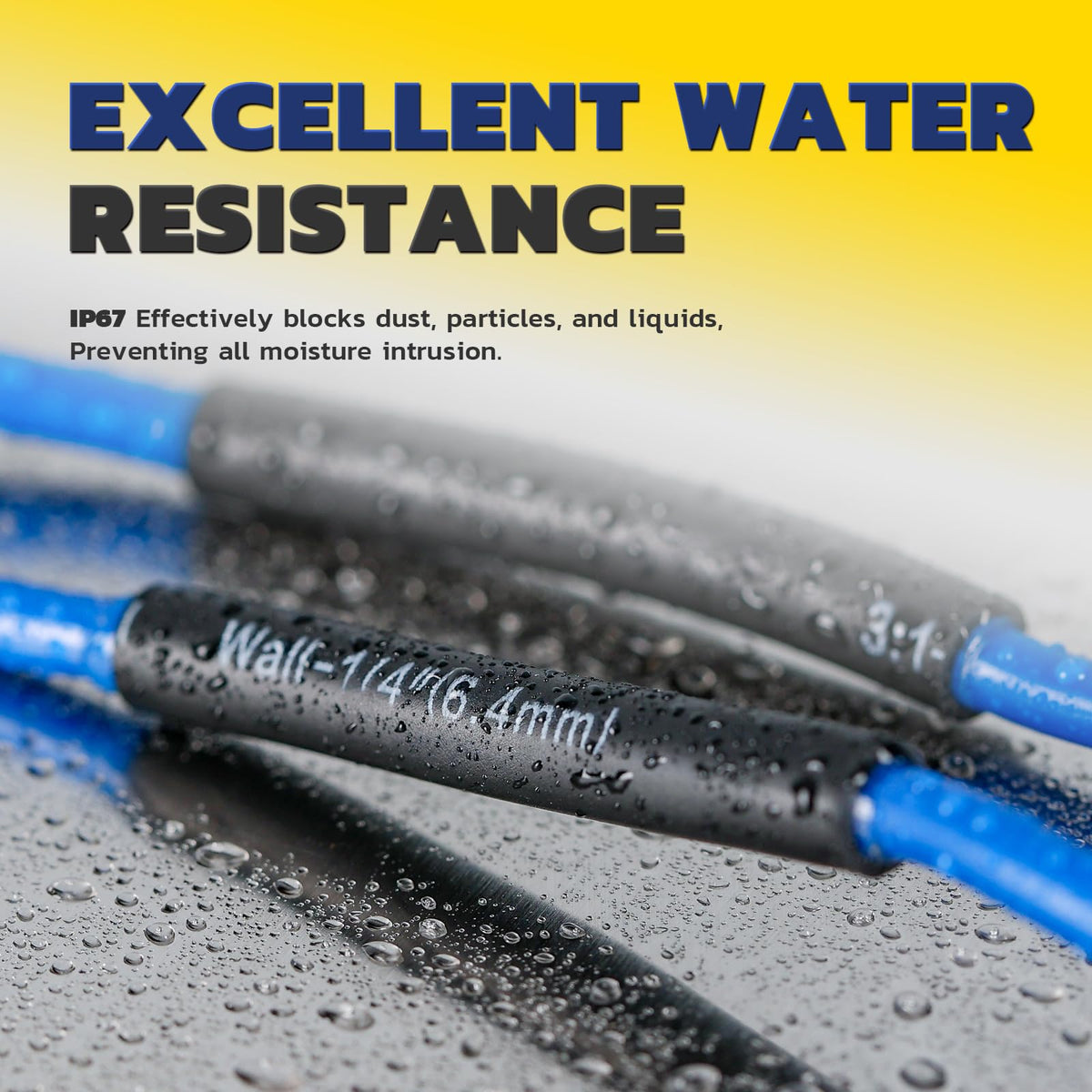
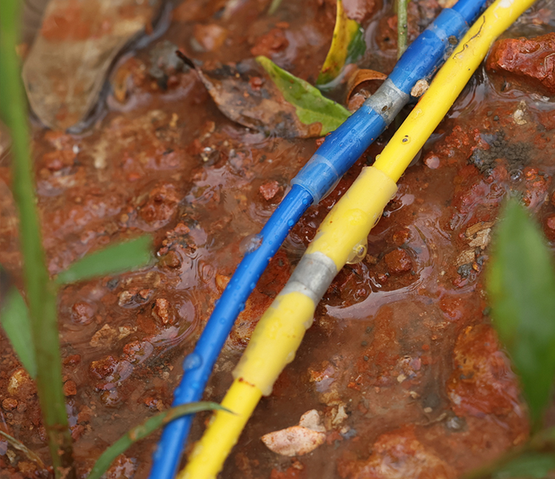
Automotive splash, bilge humidity, road spray, and condensation call for sealed connections and protected routing.
2. Why solder wicking creates a stress transition
When solder flows into stranded wire beyond the intended joint, it can bind the strands into a rigid section. The wire then changes abruptly from stiff to flexible at the edge of the soldered zone. Under repeated bending, that transition can concentrate stress.
What happens at the joint
- Solder can travel between conductor strands.
- The soldered length loses strand-to-strand flexibility.
- Movement shifts to the first flexible point outside the joint.
Why routing still matters
- A crimp can also fail if the wire hangs from the barrel.
- Sharp bends at the sleeve edge create leverage.
- Clamps and service loops keep motion away from the termination.
3. Crimp vs. solder seal: practical vibration comparison
| Decision factor | Sealed crimp connector | Solder seal sleeve |
|---|---|---|
| Mechanical joint | A matched die cold-forms the metal barrel around the conductor for a repeatable grip. | Depends on solder flow, conductor overlap, support, and controlled heating. |
| Repeated vibration | Usually the preferred route when the crimp and strain relief are correctly completed. | The soldered zone becomes stiffer; unsupported movement at the sleeve edge can raise fatigue risk. |
| Installation heat | The electrical joint is completed before heat is used to recover and seal the sleeve. | Heat must melt the solder ring and shrink the sleeve without scorching insulation or overheating the wire. |
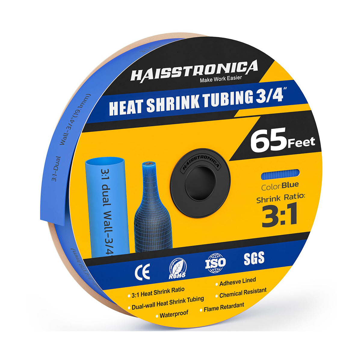
| Moisture protection | Adhesive-lined heat shrink seals around the insulation when evenly recovered. | Integrated seal rings and shrink tubing can seal when fully recovered and correctly sized. |
| Best-fit environment | Automotive, marine, trailer, mobile equipment, pumps, and exposed outdoor repairs. | Compact, lower-vibration projects where access and project requirements favor a heat-only connection. |
| Product route | Choose Sealed Butt Connectors → | Compare Solder Seal Options → |
4. Choose the route by application
Use a sealed mechanical crimp
Match the barrel to the conductor, complete the full crimp cycle, recover the adhesive-lined sleeve, and support the cable near the joint.
- Engine and chassis harness repair
- Trailer and towing circuits
- Boat, dock, pump, and outdoor equipment
Compare solder seal only where appropriate
Use the correct wire overlap and controlled heat, then support the joint so the wire does not flex repeatedly at the sleeve edge.
- Protected low-current connections
- Tight spaces with limited tool access
- Projects that permit this connection method
5. Match connector size, AWG, and the crimping die
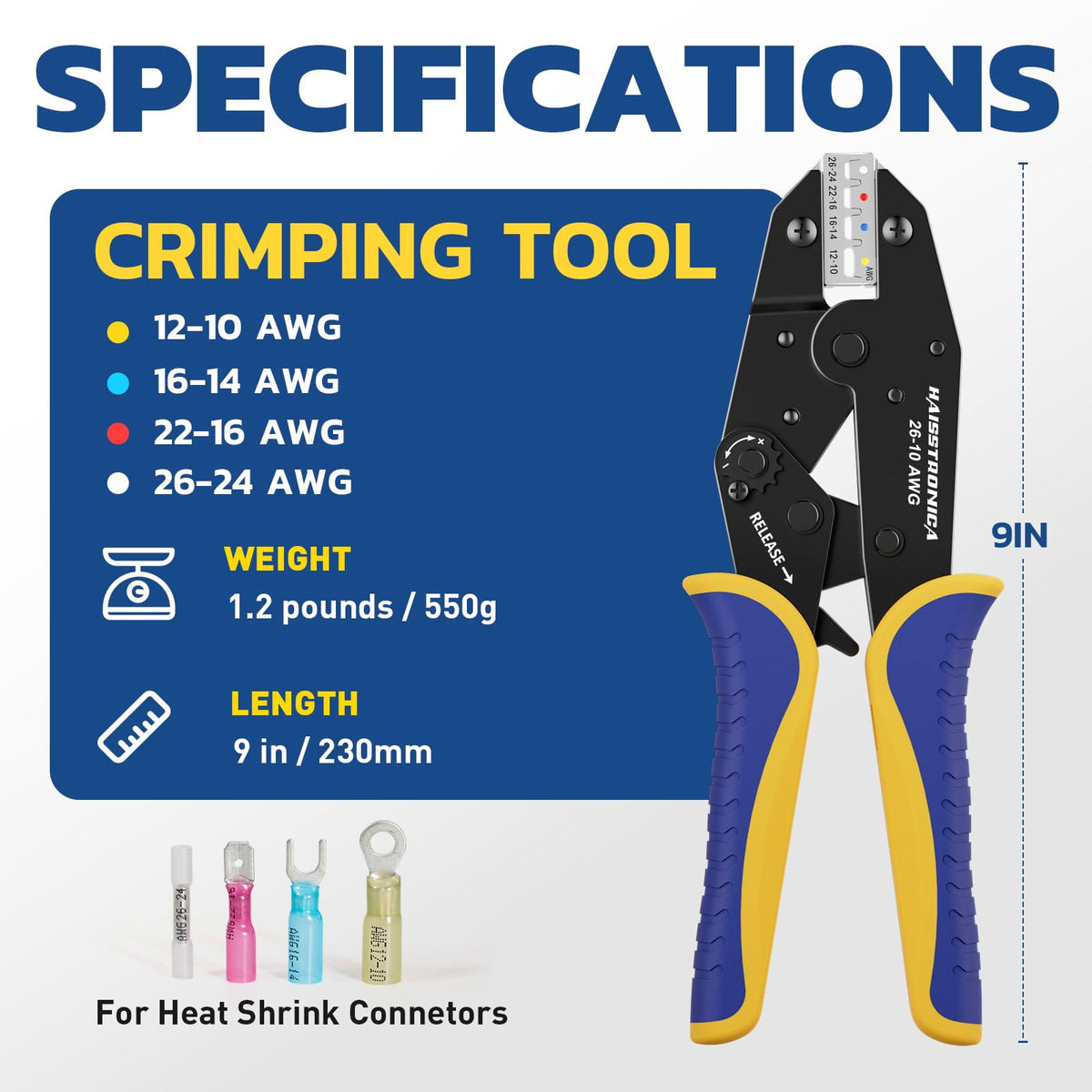
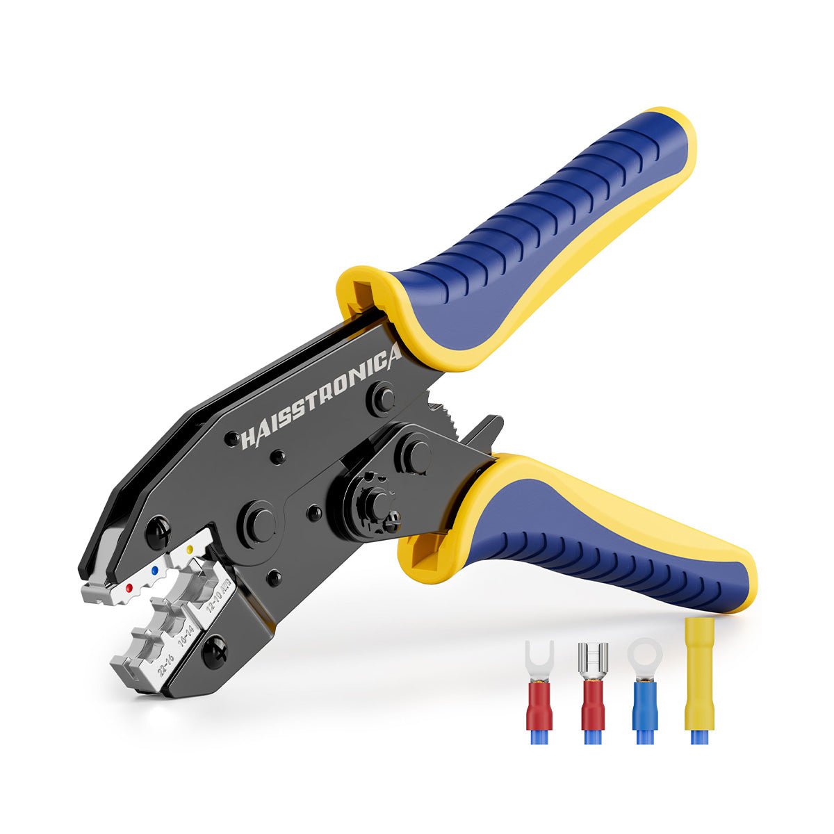
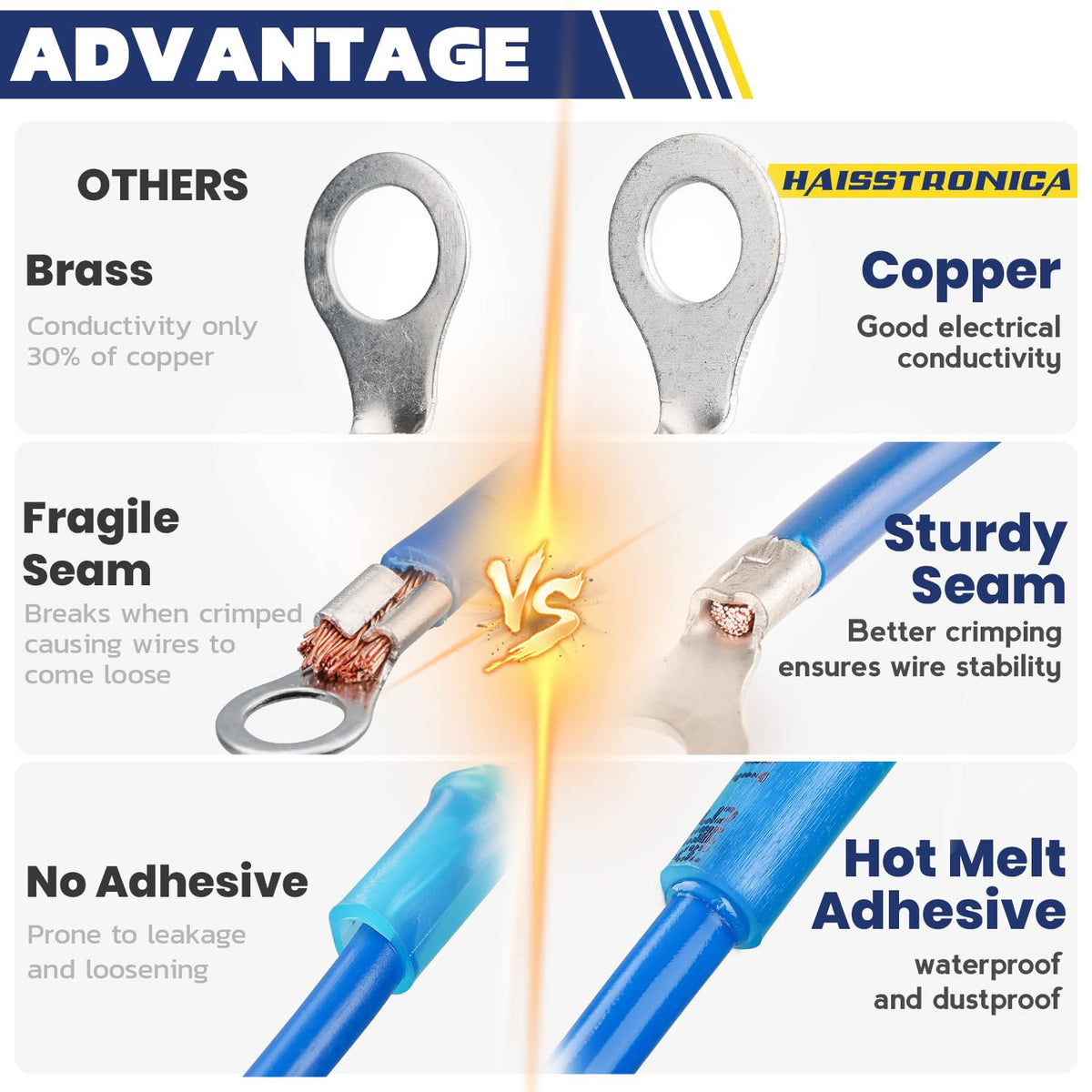
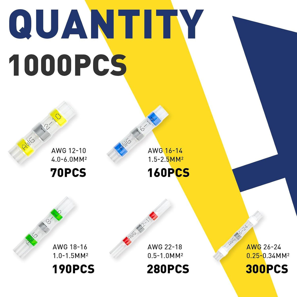
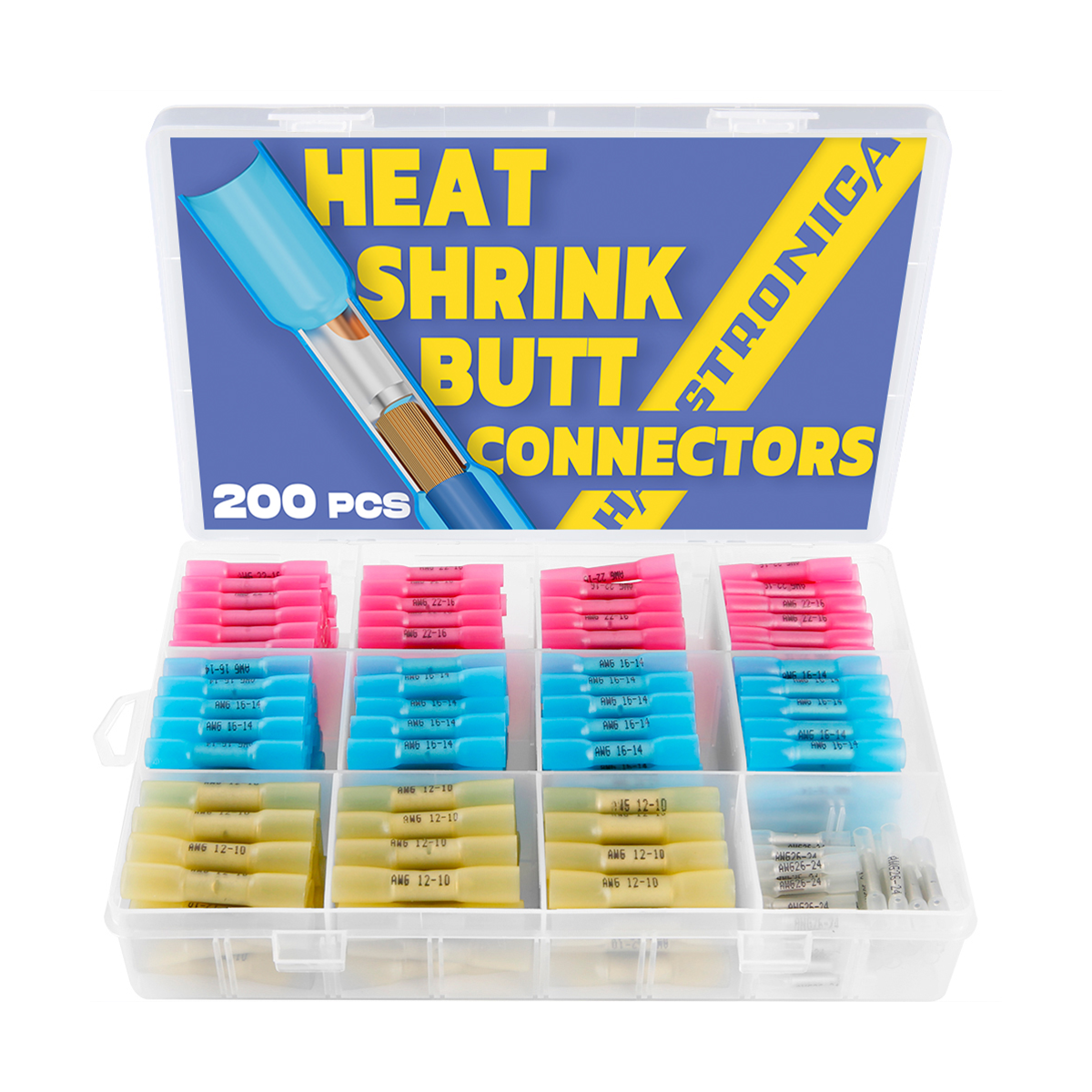
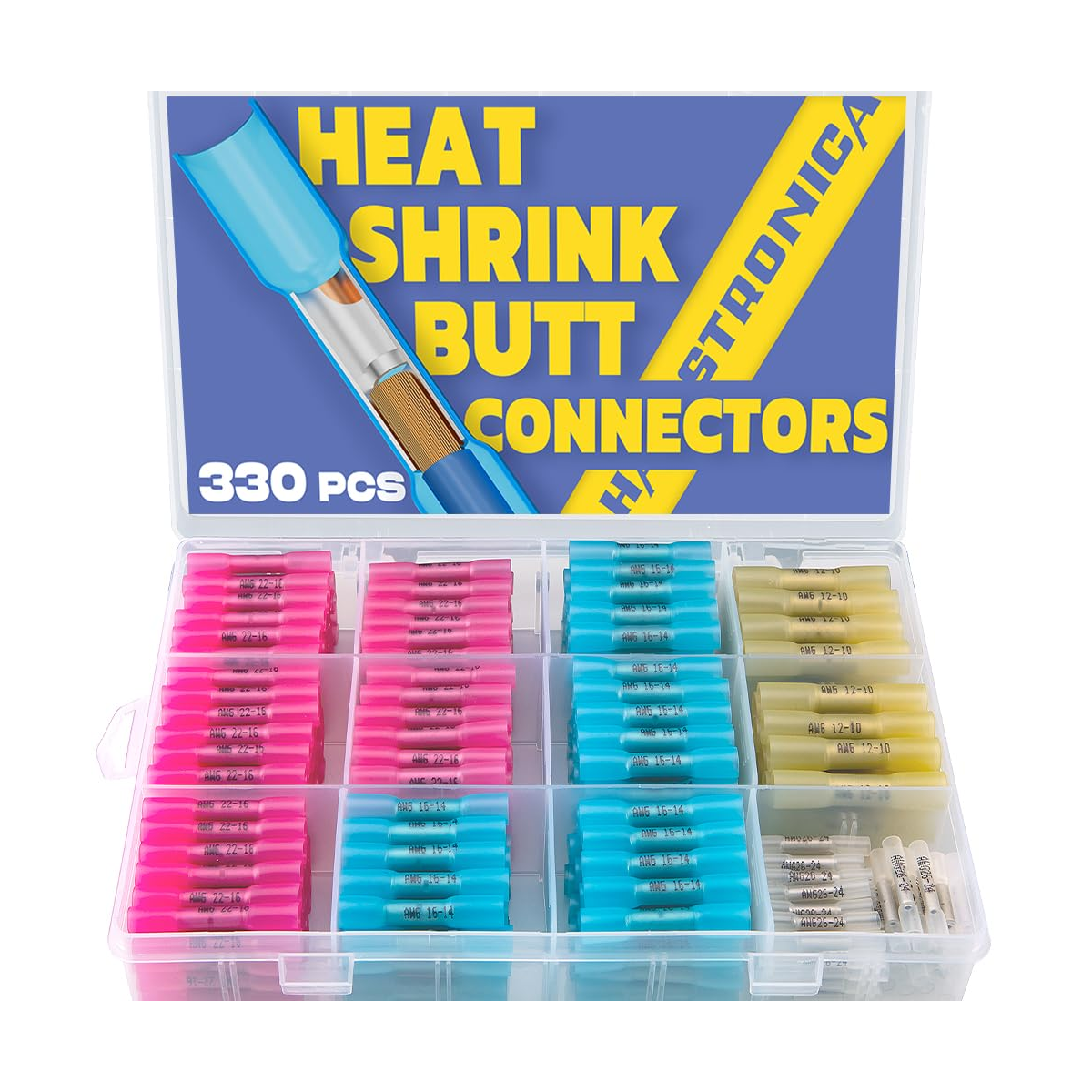
Connector color is a quick guide, but the printed conductor range and the connector specification are the final authority. Match the metal barrel—not only the outer sleeve—to the conductor.
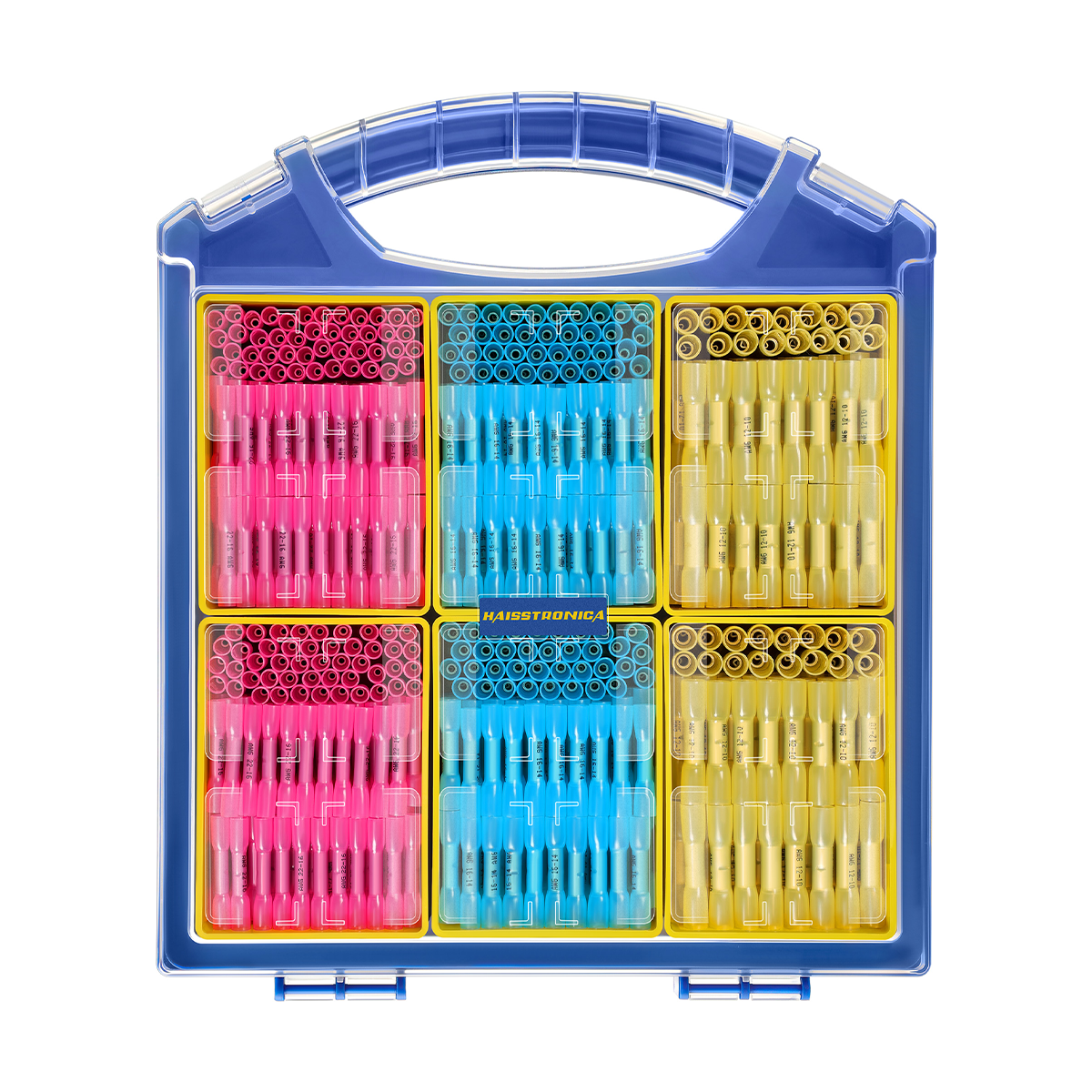
| Common color | Typical range | Crimp requirement | Product route |
|---|---|---|---|
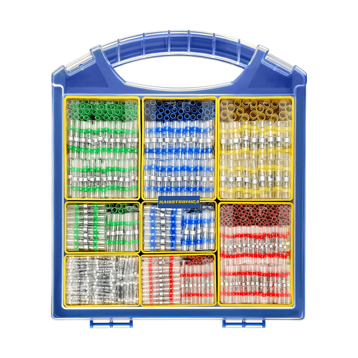
| White | AWG 26–24 | Use the cavity specified for the connector; confirm fine-wire compatibility. | Browse Connectors → |
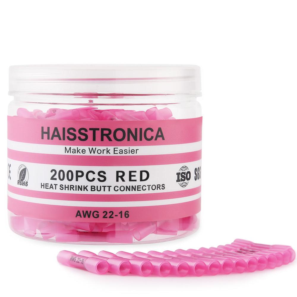
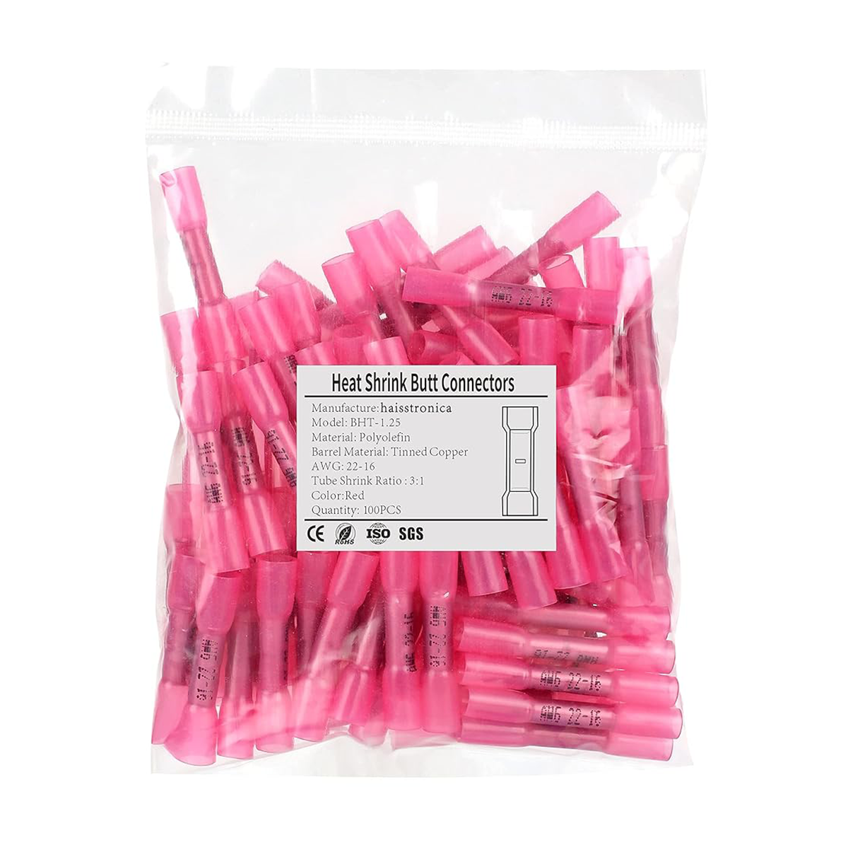
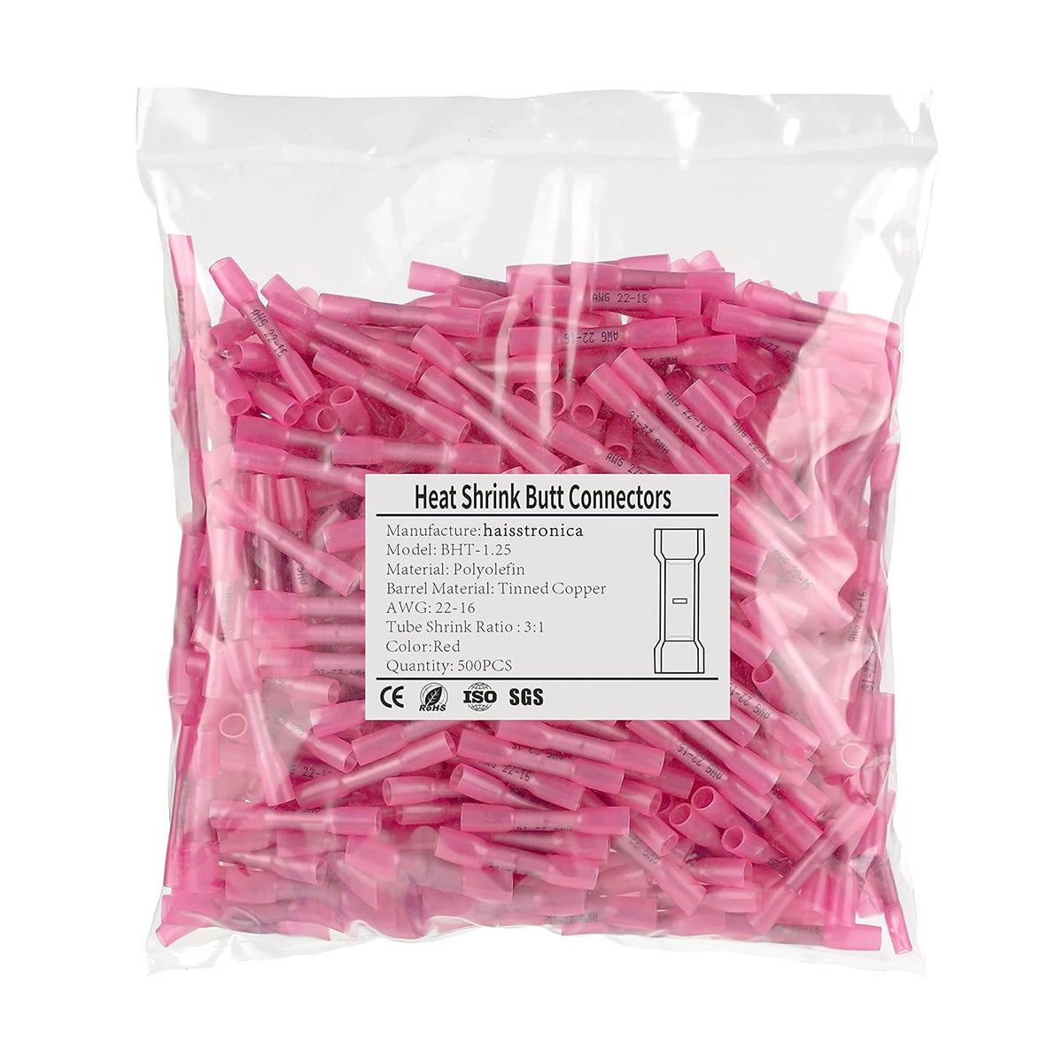
| Red | AWG 22–16 | Center the hidden metal barrel in the matching insulated-terminal die. | Choose Butt Connectors → |
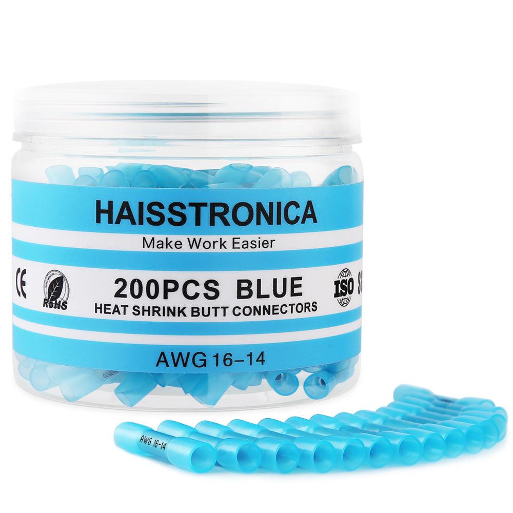
| Blue | AWG 16–14 | Confirm the conductor fills the barrel without forcing or folding strands. | Browse Terminal Kits → |
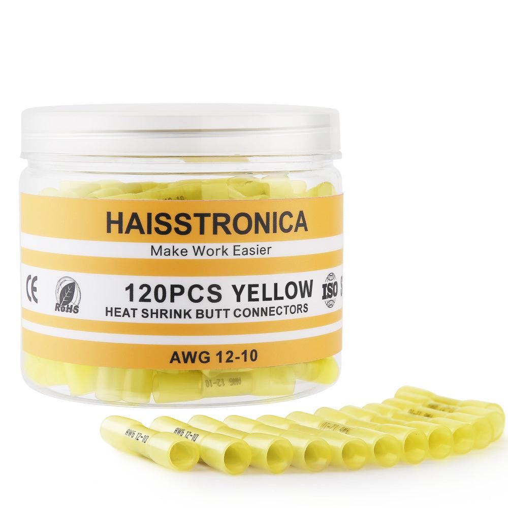
| Yellow | AWG 12–10 | Use the correct cavity and complete the full ratchet cycle before heating. | Browse Terminal Kits → |
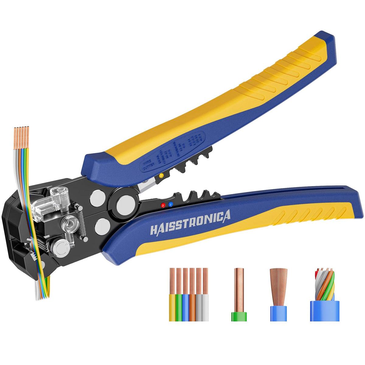
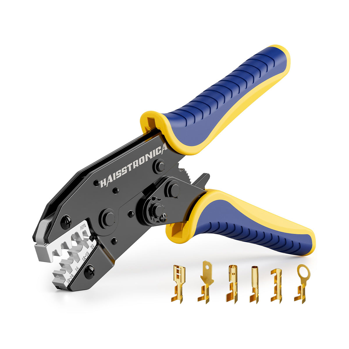
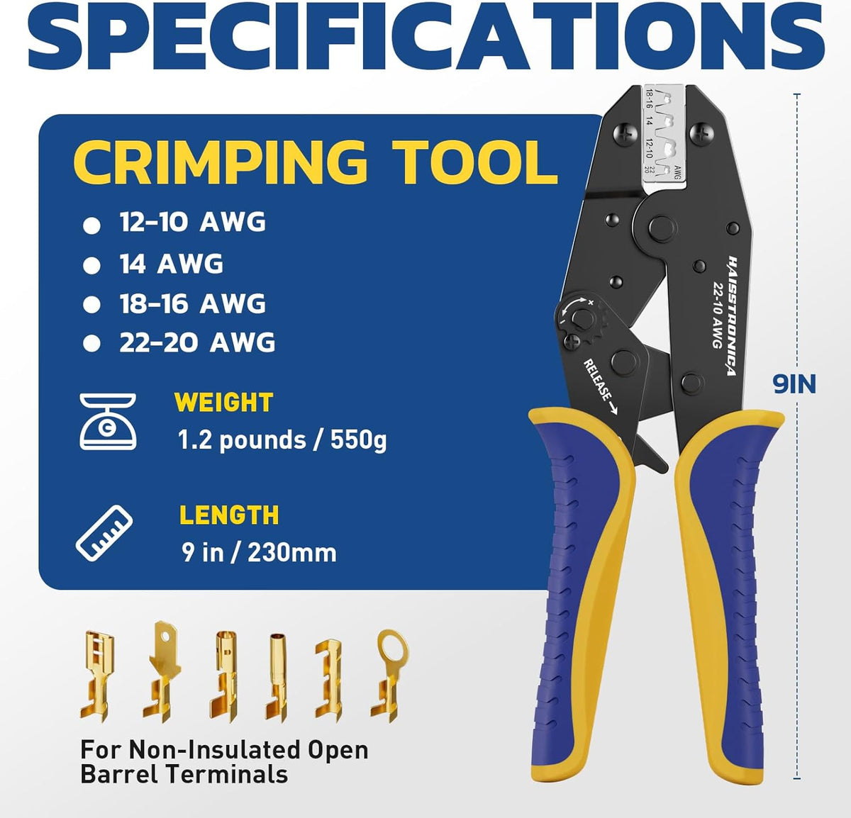
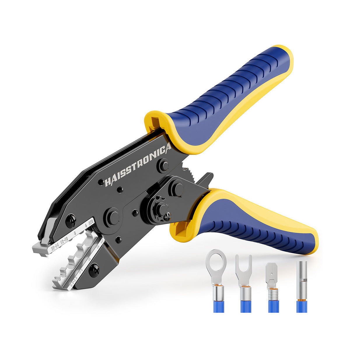
6. Use a matched ratchet crimper
Why the die matters
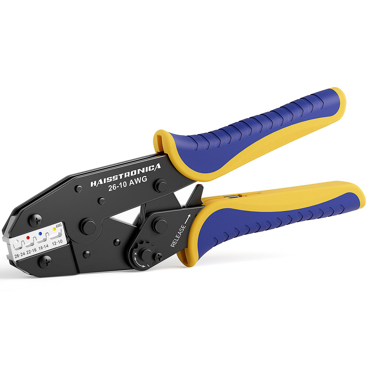
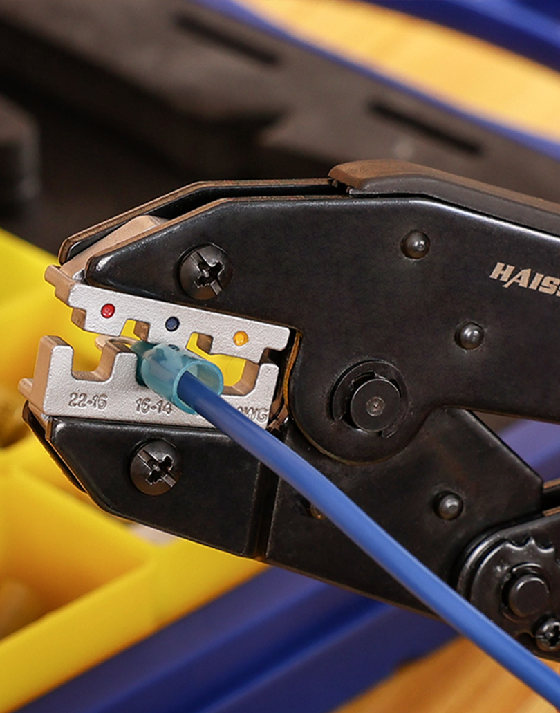
A smooth, correctly sized insulated-terminal die places pressure over the metal barrel. Pointed, staking, or mismatched jaws can cut the sleeve, deform the barrel, or produce an incomplete compression.
Browse Wire Crimper Collection →Why the ratchet cycle matters
A full-cycle mechanism helps maintain a repeatable compression. Do not stop halfway, crush the joint twice in different positions, or crimp the soft sleeve edge.
Shop AWG 22–10 Ratchet Crimper →7. Complete the vibration-resistant connection
Confirm the circuit
Disconnect power. Identify conductor material, stranding, AWG, current, temperature, vibration, and moisture exposure.
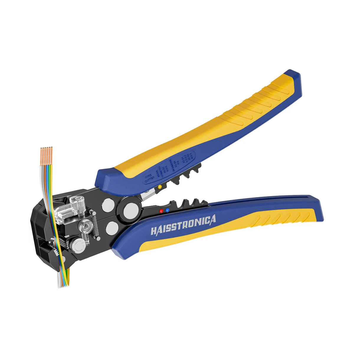
Strip without nicking
Expose only enough conductor to fill the metal barrel. Keep all strands intact and copper inside the sleeve.
Center the barrel
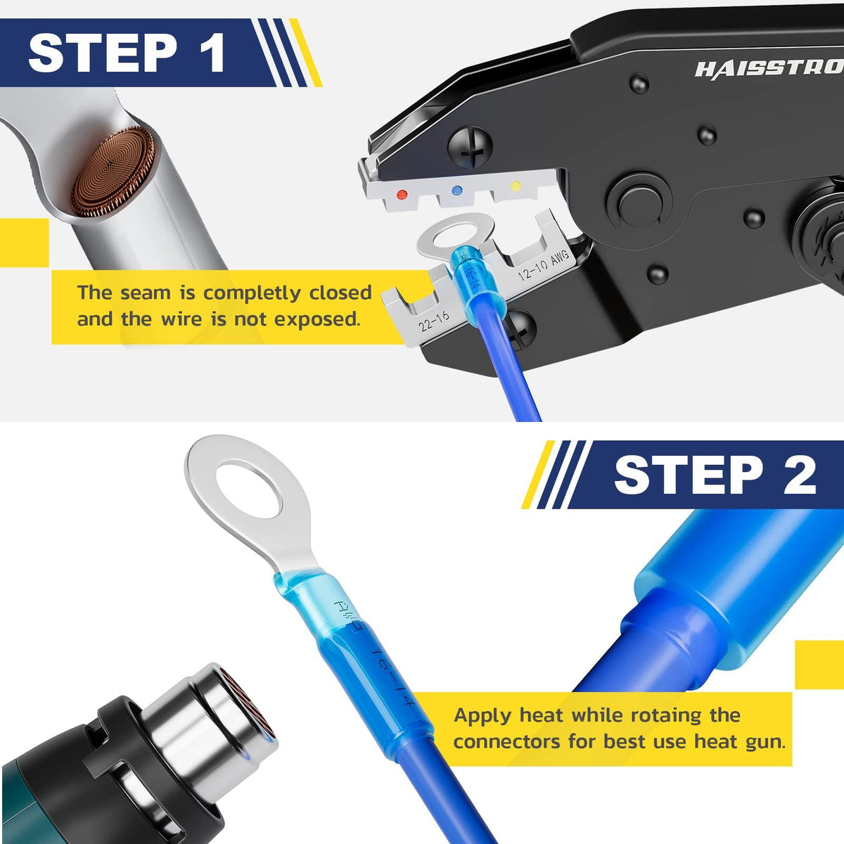
Place the hidden metal barrel—not the sleeve edge—in the correct die cavity.
Use the Matched Crimper →Complete and pull-test
Finish the full ratchet cycle. Inspect alignment and apply a firm pull before heating.
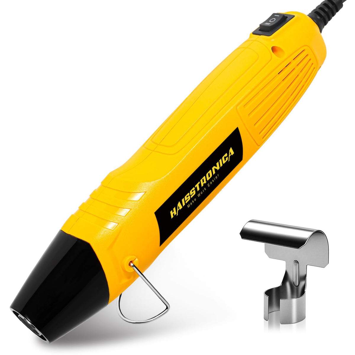
Heat evenly
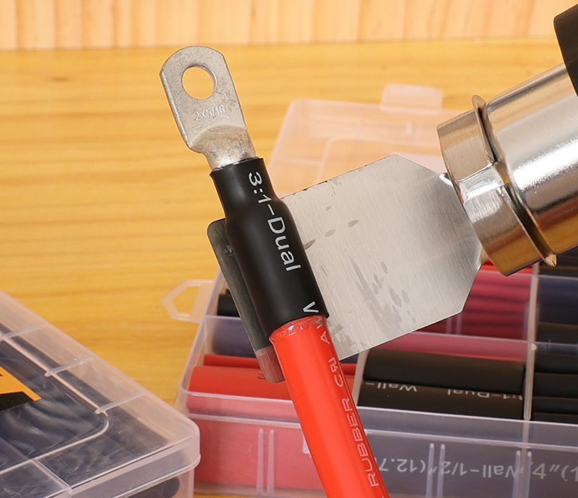
Rotate the joint and use controlled heat until the sleeve fully recovers and adhesive appears at the edges. Do not scorch it.
Add strain relief
Route and clamp the wire so vibration does not bend it at the barrel or sleeve edge. Keep a gentle service loop.
Strain relief is part of the connection
Do
- Clamp the harness near the joint without crushing it.
- Use gentle bends and adequate service slack.
- Keep the splice away from sharp edges and direct heat.
- Support both sides when the joint bridges moving parts.
Avoid
- Letting the connector carry the cable's weight.
- Placing the joint at a hinge or repeated flex point.
- Stretching wires tight between fixed mounts.
- Using tape as the only mechanical support or moisture seal.
Products matched to the system
Heat Shrink Butt Connectors
Sealed inline splices for compatible automotive, marine, and outdoor conductors.
Shop Butt Connectors →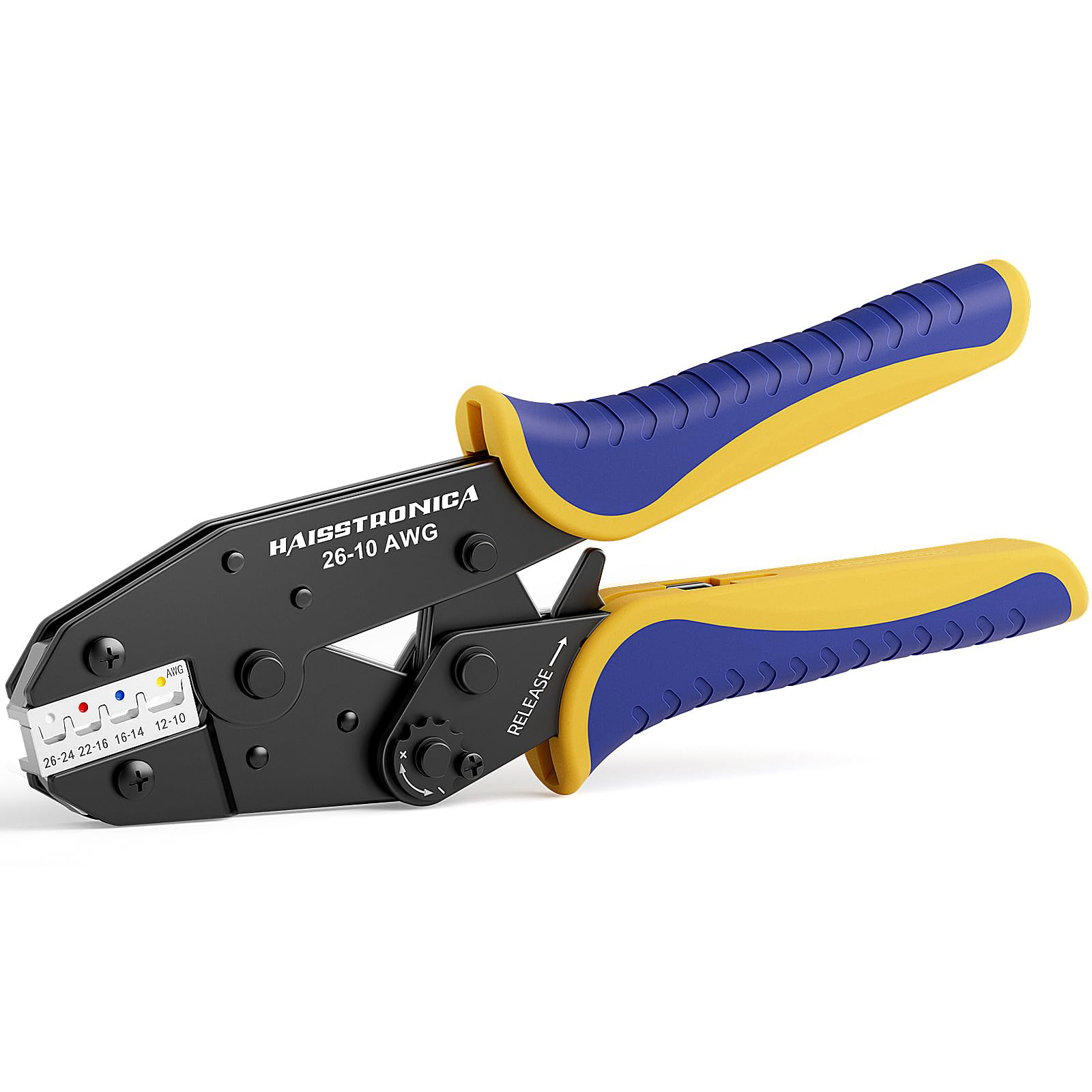
AWG 22–10 Ratchet Crimper
A matched crimping route for common heat-shrink insulated terminal sizes.
Shop Ratchet Crimper →
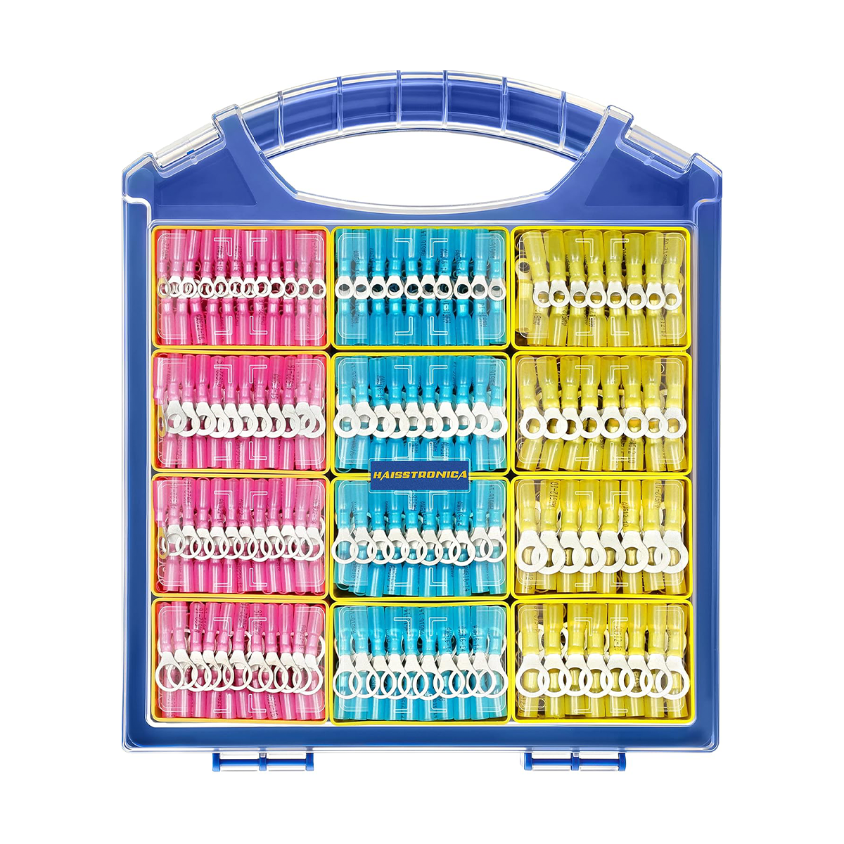
Heat Shrink Terminal Kits
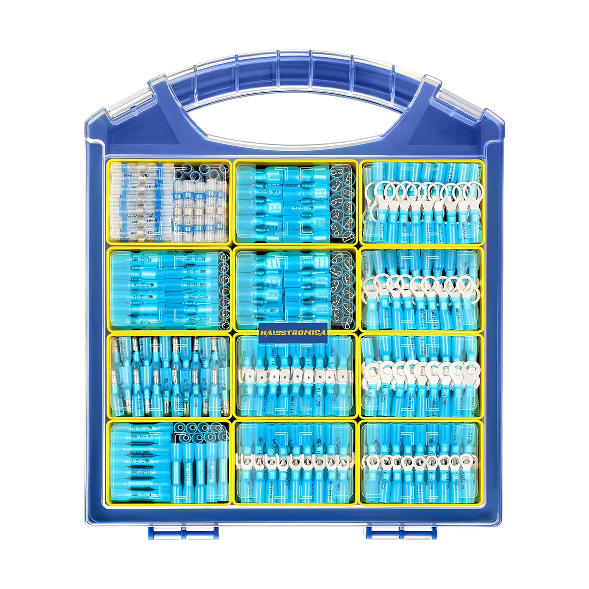
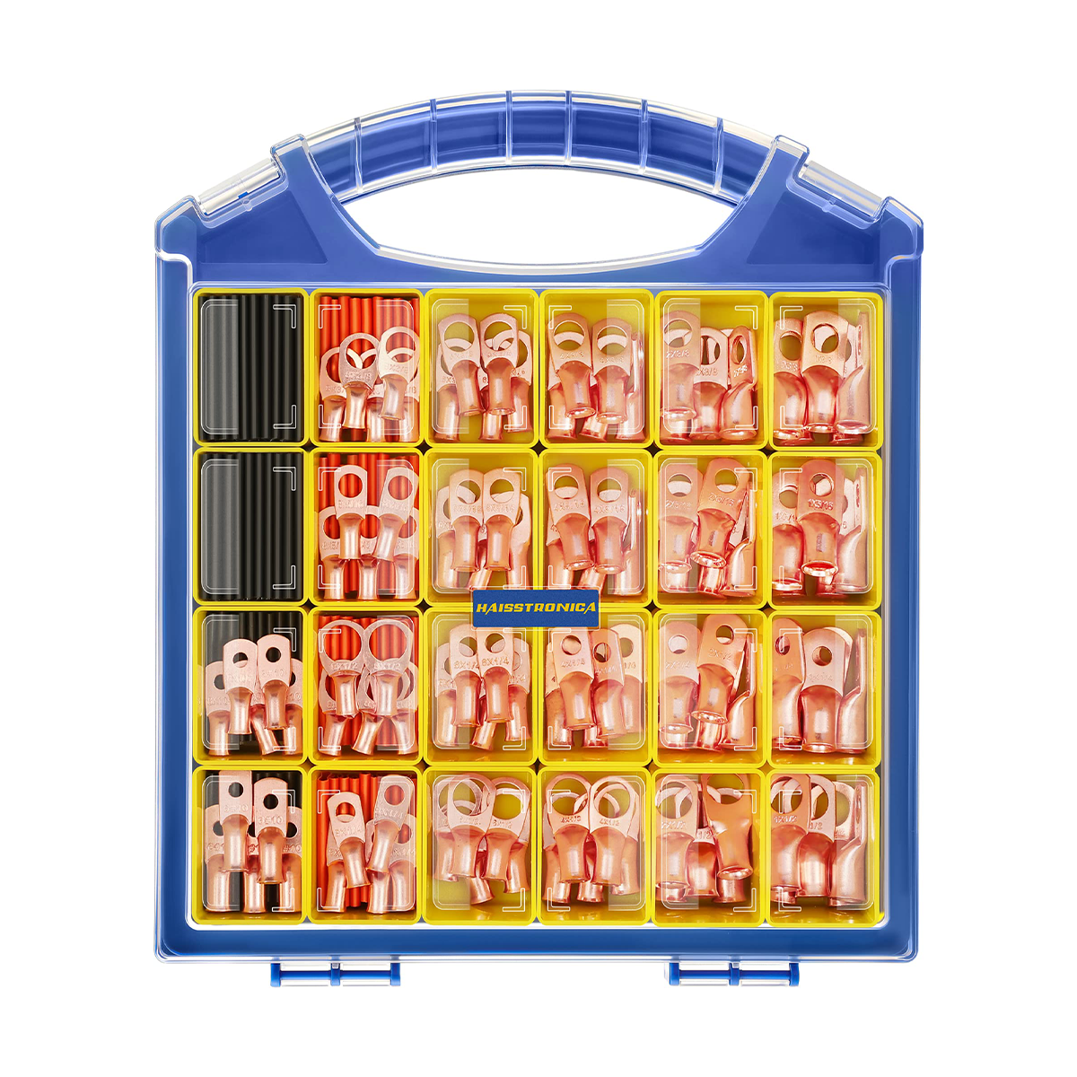
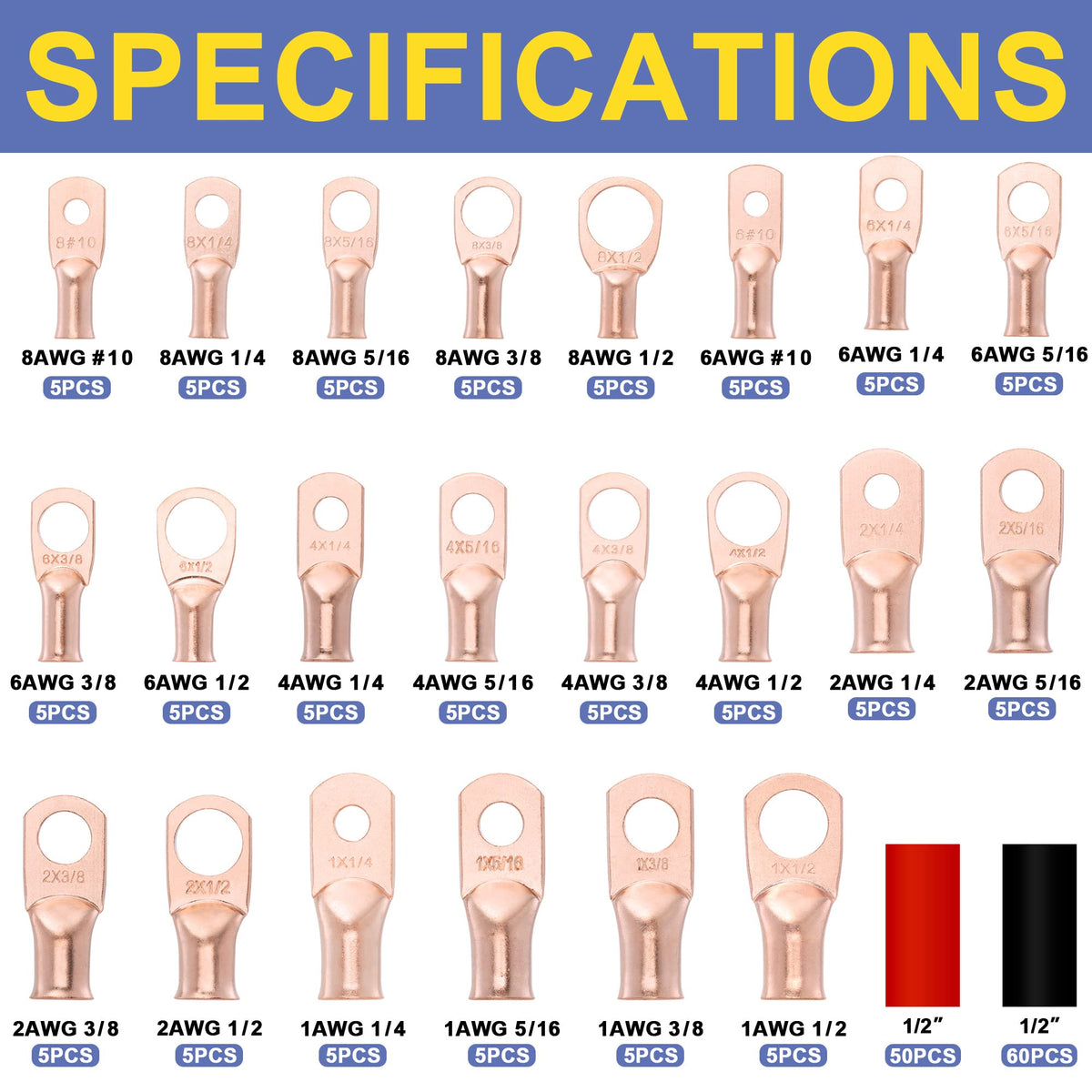
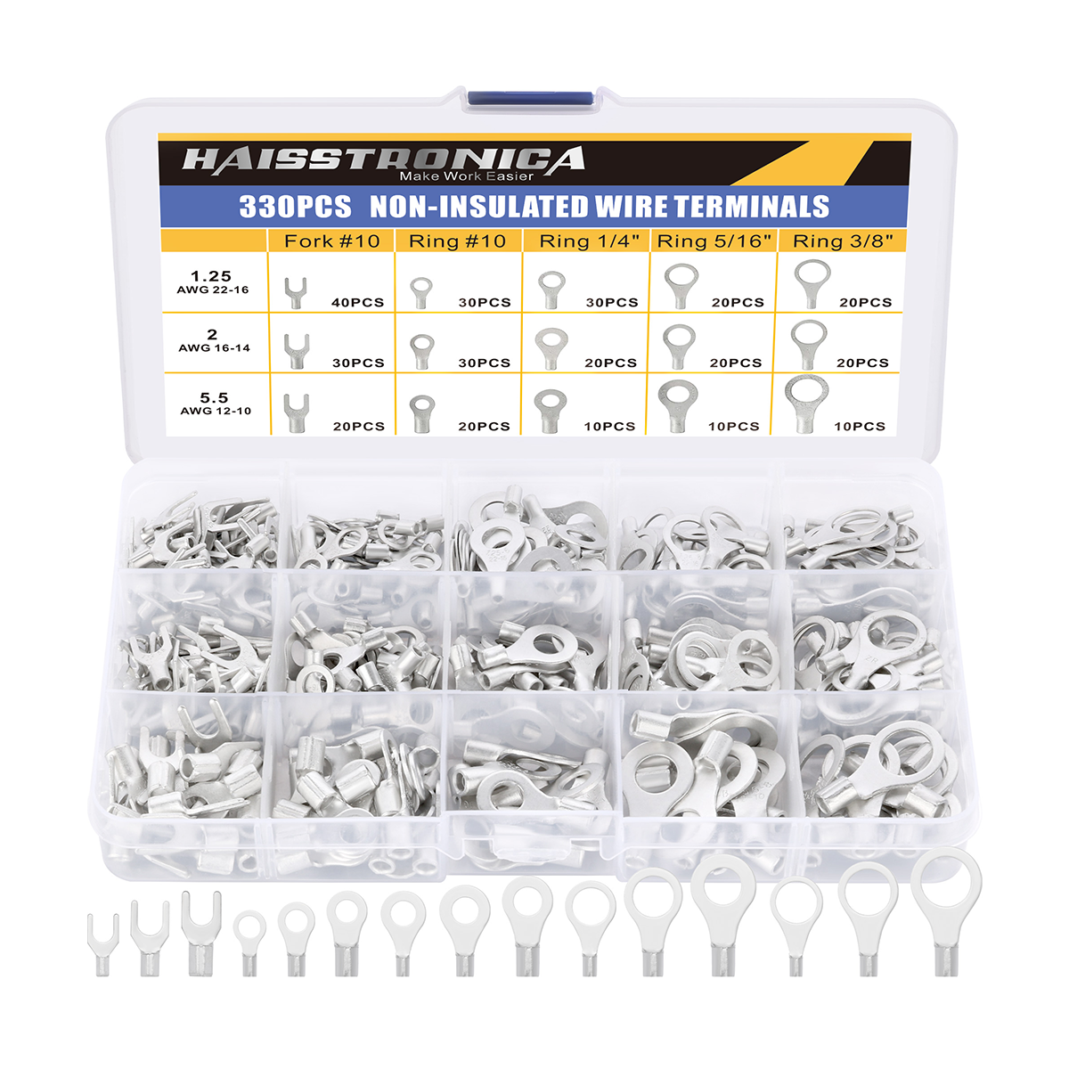
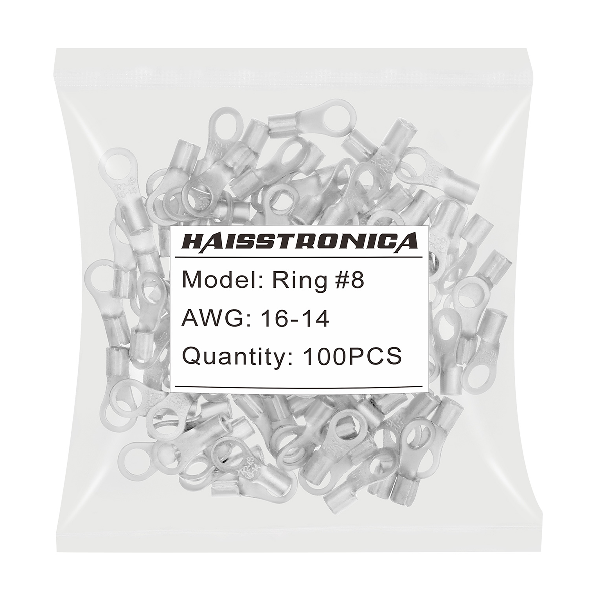
Ring, fork, spade, bullet, and mixed terminal routes for compatible wire sizes.
Browse Terminal Kits →Choose by vibration—not convenience alone
For automotive, marine, trailer, and mobile equipment, start with a sealed crimp connector, a matched ratchet tool, and deliberate strain relief. Keep solder seal as a comparison route for compact, lower-vibration work where the project requirements permit it.